manuals.online logo
Brands
  1. Home
  2. •
  3. Brands
  4. •
  5. ATO
  6. •
  7. Chiller
  8. •
  9. ATO ATO-JL3000 User manual

ATO ATO-JL3000 User manual

Industrial Laser Chiller
Instruction manual
ATO-JL3000;ATO-JL5000;ATO-JL5200
Read this instruction manual in detail before installation and use!
Ⅰ.Installation Precautions:
1. Ensure that the working voltage is stable and normal and the power frequency match is correct. (Normal use of equipment
voltage value for single-phase 200-240v, three-phase voltage of 380v, power supply frequency is divided into 50HZ and 60HZ.
2. Add water first, then take over, to discharge the air bubbles in the water circuit.
3. It is forbidden to turn on the machine without water, otherwise, the circulating water pump motor will be burnt.
4. Ensure that the equipment air outlet and air inlet are smooth and that the dust net and air outlet are regularly cleaned. (Inlet
and outlet blockage, air does not convection, heat cannot be discharged, easy to produce high-temperature alarm and other
machine failures.)
Ⅱ.The Installation Process:
1. Open the box to check whether the machine and accessories are complete.
2. (Random accessories: a power cord, a set of water pipe connectors, a manual)
3. Open the lid of the water injection port and add cooling water.
4. (Distilled and purified water is preferred, in case of cold weather in the north, the cooling water should add a certain
proportion of non-corrosive antifreeze or industrial alcohol to prevent freezing and damage to components, and the water level
should be
Freezing damage to parts, the water level should be in the green marking line part)
5. Connect the water pipe according to the indication mark, and turn on the power.
6. (The first time you start to use the machine pay attention to whether the water leakage. Quality problems immediately
contact the manufacturer after-sales service; followed by the water level is still in the normal reasonable position)
(normal reasonable position)
7. Adjust the thermostat parameters required to connect the equipment.
(JL-5200 generally does not need to adjust the temperature value again, the factory value of 27 degrees constant temperature,
according to customer demand whether to adjust again)
Ⅲ, The controller Overview:
This series of controllers is suitable for chiller control. By starting and stopping the refrigeration compressor and controlling the
refrigerant solenoid valve and electric heating rod, it can realize the precise control of water temperature.
Controller Features:
1. Using refrigerant solenoid valve to control the compressor's cooling capacity.
2. With heating function to ensure that when the ambient temperature is low, it can still work stably.
Technical parameters:
—Temperature measurement range: -45℃~99.9℃ —Temperature control range: -30℃~90℃
—Expression error (measurement accuracy): -15 ℃~ 60 ℃± 1 ℃± 0.5 words, the rest ± 2 ℃± 0.5 words
—Resolution: 0.1℃
—Installation size: 92*43 Opening size is larger than 93*44 —1 way buzzer alarm output
—Relay contact output capacity: Compressor 16A/220VAC, solenoid valve 5A/220VAC, electric heating rod 16A/220VAC, alarm
relay 3A/220VAC. (or compressor 30A/220VAC, no heating relay)
—Operating voltage: 220VAC±10%, 50/60Hz. —Power consumption of the whole machine: ≤ 3W
—Operating ambient temperature: -5 ℃~55 ℃. Working relative humidity: 10% ~ 90% non-condensing.
—Storage temperature: -25℃~75℃.
—Sensor NTC (10KΩ/25℃, B value 3435K) —Two output sensor wire length: 0.8 meters
Configuration Diagram:
Water Temperature Probe
Sensor
Room Temperature Probe
Sensor
Cooling
Heating
RY1001A
●
●
●
●
Note: "●" means there is this function item, "---" means there is no this function item.
IV. Operation and Display Panel
1. Panel Display Operation
The display panel can show six digits, nine kinds of status indicators (compressor-comp, solenoid valve-solenoid valve,
electric heating rod-heating, intelligent mode-INT ctrl, constant temperature mode-CT ctrl, parameter setting-PARAM set,
alarm output-ALM output, display room temperature-Room temp, power-on delay (ST delay).
Under normal operation, the upper display window shows the normal water temperature and the lower display window
shows the set water temperature.
2. Description of Work Indicator Status
Name
Notation
State
Express a Meaning
Compressor
Indicator light
Comp
lights up
Compressor start up
lights out
Compressor off
Refrigerant Solenoid
Valve Indicator Light
Solenold Valve
lights up
Refrigerant solenoid valve start up
lights out
Refrigerant solenoid valve off
Heating Rod
Indicator Light
Heating
lights up
Heating rod start up
lights out
Heater bar off
Intelligent Control
Mode
INT ctrl
lights out
Controller operates in non-intelligent control mode
lights up
Controller operates in intelligent control mode
Thermostatic Mode
CT ctrl
lights out
Controller operates in non-thermostatic control
mode
lights up
Controller operates in thermostatic control mode
Parameter Setting
Mode
PARAM set
lights out
Controller operates in non-parameterized mode
lights up
Controller working in parameter setting mode
Alarm Output Mode
ALM output
lights out
Non-alarm output state
lights up
Alarm output state
Display Room
Temperature Status
Room temp
lights out
Display non-room temperature status
lights up
Display room temperature status
Power on Delay
Status
ST delay
lights out
Non-power on delay state
lights up
In power-on delay state
3. Description of Keys
There are six keys on the controller:
:Left shift key :Right shift key key
:Upward key :Downward key SET Key
V. Operating Instructions:
1. Manufacturer Parameter Adjustment Method
Press and hold down , SET power button, three seconds after the display "99", press ▲▼ a key to modify the factory
settings of the password "XX", and press SET key to enter the menu settings, you can modify the factory settings. Key to enter
the menu settings, you can modify the factory settings, and you can change (the F0-A11) parameters.
Any time to return to the key, then save the modified parameters to exit the parameter setting state, return to the
temperature display, and run according to the new parameters. If no key is pressed within 20 seconds, the controller will also
automatically exit the parameter setting state and not save the modified parameters. If the password is wrong, press SET to
return to the temperature display.
2. User Parameter Adjustment Method
First press and hold the ▲key, then press the SET key at the same time for 5 seconds. The upper limit window displays
"00" and the lower display window displays "PAS". At this time, press the ▲▼ keys to select the set password.
After entering the code, press the SET key again. If the password is correct, the display in the lower display window changes
to parameter item F0, and the upper display window displays the parameter value of F0, entering the setting state.
Indicates that the controller is currently in a parameter setting state. If the password is wrong, the temperature display will
return. After entering the setting state, press the left and right keys to change the parameter items in sequence. Press the ▲
▼keys to change the parameter value of the parameter item.
Press the key at any time to save the modified parameters and exit the parameter setting state, returning to the
temperature display and run with new parameters. If no button is pressed within 20 seconds, the controller will automatically
exit the parameter setting state and will not save the modified parameters. In parameter setting, there is no response when
pressing SET.
Order
Code
Set Project
Range
Factory Setting
Note
1
F0
Setting temperature
F9~F8(-30~
50)
25
Intelligent Temperature Control Mode
/ Constant Temperature Mode
2
F1
Temperature difference
-15~5
-2
3
F2
Refrigeration return
difference
0.1~9.0
0.8
4
F3
Control mode
0~1
1
0 Thermostat, 1 Intelligent
5
F4
Water temperature over high
alarm
1~80
10
6
F5
Water temperature over low
alarm
1~40
15
7
F6
Air temperature over high
alarm
40~50
45
8
F7
Password
00~99
6
9
F8
Maximum set water
temperature
(F9+1)~50
30
10
F9
Minimum set water
temperature
—30~(F8-1)
20
11
A0
Heating Return Difference
0.1~5.0
0.5
12
A1
Alarm delay time
0~30
5
Minutes
13
A2
Power on delay
10~300
15
Seconds
14
A3
State transition delay
00~99
5
Seconds
15
A4
Room temperature
correction
-10.0~10.0
0
16
A5
Water temperature
correction
-10.0~10.0
0
17
A6
System inertia coefficient
0~40
8
The smaller the value, the more
accurate the precision
18
A7
Compressor start-up
protection
0~300
30
seconds
19
A8
Electric heating rod control
return
-5.0~20.0
0.2
Heater operates when water
temperature <F0-A8
The heater stops working when the
water temperature is >F0-A8
20
A9
Input signal alarm delay
00~99
2
Seconds
21
A10
Input signal normally open
and closed setting
NO/NC
NC
NO is normally open NC is normally
closed
22
A11
Solenoid valve open delay
0-0.4
0
F0-A11 solenoid valve
23
A12
Functions in case of E6 alarm
0/1
0
0 for normal operation, 1 for system
stop
24
A13
External alarm output
recovery delay
00~99
2
Seconds
25
A14
Compressor startup solenoid
valve delay off
0~33
0
Seconds
26
A15
Er1-Er5 signal relay status in
alarm
0/1
0
1 output 0 no output
3. Rapid Restoration of Factory Settings
In the case of power-on normal display, non-setting, press and hold ▲▼ key at the same time, the thermostat will be
powered on, and "rE" will be displayed after 3 seconds, and all the set values will be restored to the factory values, and then
resume normal working condition after another three seconds.
4. Check the Room Temperature
In a non-setting state, press ▼a key to display the room temperature sensor detection value, after 6 seconds resume
displaying the water temperature (at this time Room temperature light is on, indicating that the upper window is displaying
room temperature).
5. Quick Adjustment
Press the SET key when the thermostat is working normally if the thermostat is working in constant temperature mode, the
panel displays the parameter value of F0 (set temperature) and the intelligent mode display F1 (temperature difference value)
parameter value (at this time the panel PARAM set light is on, indicating that the controller is now in parameter setting state).
At this time, press ▲▼ a key to modify the set value, and then press SET key to exit If no key is pressed within 20 seconds,
then it will not save the disk to exit. If you press key, it will save the disk and exit, and the new parameter will take effect.
Ⅵ. The Control Output Function
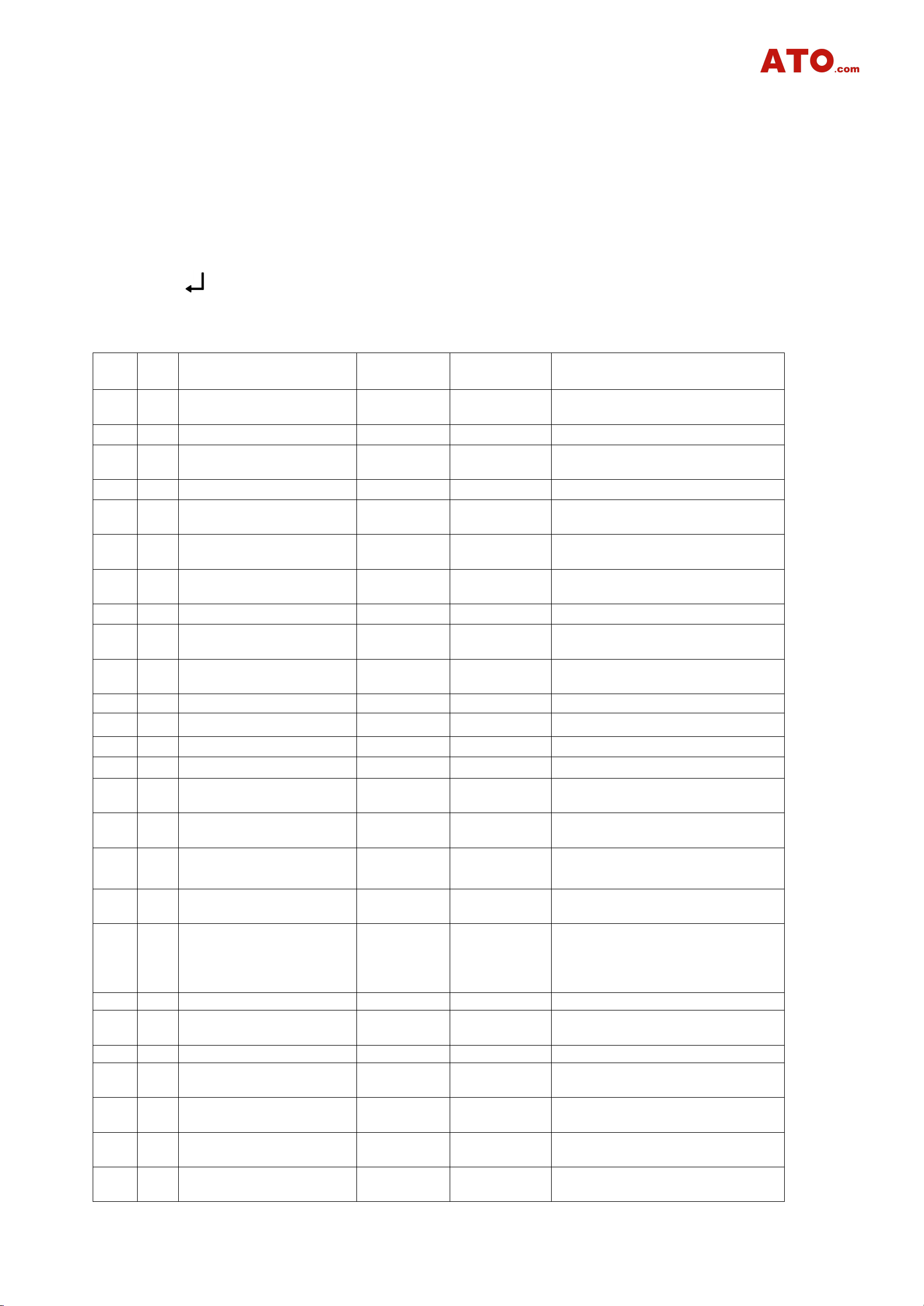
1 Refrigeration Control
Chiller Working Condition
Compressor
Working Condition
Condition of
Refrigerant
Solenoid Valve
Condition of the
Heating Rod
Note
Refrigeration
Operation
Stop
Stop
100% full power cooling
First-stage micro-refrigeration
Running
Conduction
Stop
40% power cooling
Second-stage
micro-refrigeration
Running
Conduction
Start
20% power cooling Heating
pad working
Heating
Stop
Conduction
Start
No cooling, only heating
The above are the four working states of the chiller controlled by the intelligent temperature controller. Refrigeration and
micro-cooling state conversion time is the shortest, (about 5-10 seconds) and can be converted several times in one minute. If
the thermal load is turned on, the chiller mainly works in these two working conditions, which can precisely control the
temperature of the cooling water. (The actual test water temperature fluctuations of about 0.3 degrees or so). When the
thermal load is off, the water temperature will overshoot downward, and the refrigeration compressor will stop working when
it reaches the A0 set value.
Need to pay special attention to is; chiller condition conversion and water temperature changes between there will be a time
difference, the parameter A6 is to describe the system inertia of the relevant parameters, according to this parameter, the
controller can calculate the corresponding action in advance, reduce the water temperature overshoot.
Refrigeration Compressor: When the temperature rises to the water temperature set value + refrigeration return difference,
and the compressor protection delay over the set time, the compressor starts to work. The compressor stops working when the
temperature drops to the water temperature setting value - heating return difference.
Refrigerant Solenoid Valve:
(1). The compressor works, when the temperature drops to (equal to, below) the water temperature set value, and the
refrigerant solenoid valve cut-off duration has been greater than the time set by the state transition delay (A3), the refrigerant
solenoid valve on. When the temperature rises to (higher than) the water temperature setting value or above, and the duration
of the refrigerant solenoid valve is greater than the time set by the state transition delay (A3), the refrigerant solenoid valve
cuts off.
(2). When the compressor stops running, the refrigerant solenoid valve is on.
(3). When the compressor starts to work (startup), the refrigerant solenoid valve must be in the cut-off state (under normal
circumstances, this condition is satisfied).
Electric Heating Rod: When the water temperature decreases to below the water temperature setting value —electric
heating rod control return difference, the electric heating rod starts to work. When the water temperature rises above the water
temperature setting value - electric heating rod control return difference, the electric heating rod stops working.
2 Water Temperature Setting Value
When the thermostat operates in the constant temperature mode, the water temperature setting value is constant at F0,
just like an ordinary thermostat.
When the thermostat works in intelligent mode, the water temperature set value is variable as follows:
When the room temperature plus F1 is less than F9, the water temperature set value is equal to F9.
When the room temperature plus F1 is greater than F8, the water temperature setpoint is equal to F8.
When room temperature plus F1 is less than or equal to F8, or greater than or equal to F9, the water temperature set value
is equal to room temperature + F1.
3 Alarm Output
(1) Alarm Display
Er1
Er2
Er3
Er4
Er5
Er6
Room temperature is
The water temperature
The water
Room
Water
External
extremely high
is extremely high
temperature is
extremely low
temperature
sensor failure
temperature
sensor failure
input alarm
When alarming, all error codes and water temperature are displayed in turn.
(2) Alarm Conditions
See the setting code table:
Er1:Room temperature﹥Air temperature super high alarm value (F6 setting value);
Er2:Water temperature﹥setting temperature + refrigeration return difference F2+water temperature super high alarm F4
Er3:Water temperature﹤setting temperature-heating return difference A0-water temperature ultra-low alarm F5
Er4:Room temperature sensor short circuit or open circuit
Er5:Water temperature sensor short circuit or open circuit
Er2, Er3 to meet the power-on alarm delay (A1) or power-on forced cooling 30 seconds after the water temperature into
the target temperature band (i.e., between the set temperature and the set temperature).
(i.e. between the set temperature and the set temperature + refrigeration return difference F2) before the alarm will be
effective.
(3) Alarm Control Status
When there is an Er3 alarm, the cooling and heating relay will operate according to normal logic.
When the Er4 alarm occurs, the water temperature setting (F0) of the controller operates according to the factory setting.
(If the controller works in constant temperature mode, E4 does not alarm)
When the Er5 alarm occurs, the system should turn to a shutdown state regardless of the operation in that state.
(4) Alarm Stop Sound
In the thermostat alarm state, pressing any key can stop the alarm buzzer sound, but the alarm display will not stop until
the alarm conditions are eliminated.
(5) External Input Alarm: External input alarm signal, and meet the time delay setting A9 after the time, the display Er6, the
system control is not affected, the alarm beeper
The alarm buzzer will sound.
(6) When Er1-Er6 occurs, the alarm buzzer sounds, and when the mute alarm key is pressed, the buzzer stops sounding. The
alarm output relay is automatically reset when the fault is removed.
reset automatically.
(7) Whenever an alarm occurs (except Er3), the electric heating rod will stop working. When the alarm is lifted, the electric
heating pad will work according to logic.
4 Key Tone
There is a key tone when the controller key is pressed, and a short tone is prompted every time a key is pressed.
5) Power-up Display
After powering on the display flashes for 3 seconds while displaying the indicator and digital tube, and the buzzer sounds.
After entering the normal logic operation state.
6) Temperature Correction
Room temperature correction and water temperature correction, when the display (room temperature and water
temperature) temperature and the actual deviation can be adjusted A4, A5, for correction.
7) Power-on Processing
After the thermostat is powered on and after the power-on delay (A2) time, the thermostat enters the 100% full-power
refrigeration state for 25 seconds. Then only according to the actual air temperature, water temperature control chiller work.
(Note: This is the "power on forced cooling" function. If the water temperature is higher than the set value of the water
temperature after the forced cooling, the compressor does not need to stop when the heating is back to the difference. (This
function is designed to facilitate the maintenance work.)
4 Safety Rules
●Note:
1. Strict distinction between power supply, relay output, sensor wiring, and relay must not be overloaded.
2. All wiring changes must be made with the power supply disconnected.
3. This controller is prohibited to be used in water or excessively humid environments, and prohibited to be used in high
temperatures, strong electromagnetic interference, and strong environments.
4. Ensure that the power supply voltage is the same as the voltage labeled on the controller, and ensure the stability of the
power supply voltage.

This manual suits for next models

2

Popular Chiller manuals by other brands

A-EON WJ-5000 Series user manual

A-EON

A-EON WJ-5000 Series user manual

ATC Mergen M4512V user guide

ATC

ATC Mergen M4512V user guide

Thermo Scientific NESLAB HX Series Installation, Operation, Basic Maintenance

Thermo Scientific

Thermo Scientific NESLAB HX Series Installation, Operation, Basic Maintenance

Johnson Controls YORK YK Series installation guide

Johnson Controls

Johnson Controls YORK YK Series installation guide

Carrier 16LJ-A Series Operation manual

Carrier

Carrier 16LJ-A Series Operation manual

Midea MGRH5A-PA1Z manual

Midea

Midea MGRH5A-PA1Z manual

Technibel CHGV 64 Technical instructions

Technibel

Technibel CHGV 64 Technical instructions

Carrier 30GX Series Installation, operation and maintenance instructions

Carrier

Carrier 30GX Series Installation, operation and maintenance instructions

Trane CVHE installation instructions

Trane

Trane CVHE installation instructions

SMC Networks HRR030-A-20 Series Operation manual

SMC Networks

SMC Networks HRR030-A-20 Series Operation manual

Maximicer ICE-1000 installation guide

Maximicer

Maximicer ICE-1000 installation guide

Grainfather Glycol chiller instructions

Grainfather

Grainfather Glycol chiller instructions

York MILLENNIUM 28971AR user manual

York

York MILLENNIUM 28971AR user manual

York YD manual

York

York YD manual

Skope BB Series user guide

Skope

Skope BB Series user guide

Midea LSBLG320/MZ Technical & service manual

Midea

Midea LSBLG320/MZ Technical & service manual

Bromic Heating GM0690L instruction manual

Bromic Heating

Bromic Heating GM0690L instruction manual

ATC R Series Installation, operation & service manual

ATC

ATC R Series Installation, operation & service manual

manuals.online logo
manuals.online logoBrands
  • About & Mission
  • Contact us
  • Privacy Policy
  • Terms and Conditions

Copyright 2025 Manuals.Online. All Rights Reserved.