II K 2-2
Planned for 2000
under preparation
2.1 Environmental conditions
Mains supply - power part
Voltage, 3-phase: 230 to 500 V in acc. with IEC 38
Voltage deviation: ±10% permanent
Rated frequency: 50 Hz or 60 Hz
Static frequency deviation: 50 Hz ±2 %; 60 Hz ±2 %
Dynamic: frequency range: 50 Hz: ±5 Hz; 60 Hz: ± 5 Hz
df/dt: 17 % / s
Mains supply - Electronics supply
Voltage, 1-phase: 115 to 230 V in acc. with IEC 38
Voltage deviation: -15% / +10%
Frequency range: 45 Hz to 65 Hz
Degree of protection
Power converter module: IP 00
Paint finish
Power converter module, cover: RAL 9002 light-grey
housing: RAL 7012 dark-grey
Fig. 2.1/1: Effect of the site elevation above sea level on the
power converter's load capacity
Current reduction to (%) for armature circuit and field supply
Fig. 2.1/2: Effect of the ambient temperature on the converter
module load capacity.
Current reduction to (%) for armature circuit and field supply
Environmental limit values
Permissible ambient temp. with rated current I DC: +5 to +40°C
Ambient temp., power conv. module:+40°C to 55°C; s. Fig. 2.1/2
Alteration in the ambient temp.: < 0,5°C / minute
Storage temperature: -40 to +55°C
Transport temperature: -40 to +70°C
Relative humidity: 5 to 95%, no condensation
Pollution degree: Grade 2
Site elevation:
<1000 m above M.S.L.: 100%, without current reduction
>1000 m above M.S.L.: with current reduct., s. Fig. 2.1/1
Vibration converter module: 0,5 g; 5 Hz to 55 Hz
Noises: Size as module
(1 m distance)
A1 55 dBA
A2 55 dBA
A3 60 dBA
A4 66...70 dBA, dependent on fan
Compliance with standards
The power converter modules and cubicles are designed for industrial applications.
Within the EU, the components satisfy the requirements European guidelines, shown
in the table below.
Standards in North America
In North America, the system components
satisfy the requirements as listed in the
table below.
70
80
90
100
110
30 35 40 45 50 55°C
Please note:
applies for power converter modules only.
50
60
70
80
90
100
1000 2000 3000 4000 5000m
European Union Directive Manufacturer’s Assurance
Harmonized Standards
Converter module
Machinery Directive
89/392/EEC
93/68/EEC
Declaration of
Incorporation
EN 60204-1
[IEC 204-1]
Low Voltage Directive
73/23/EEC
93/68/EEC
Declaration of Conformity
EN 60146-1-1
[IEC 146-1-1]
EN 50178 [IEC --]
see additional
IEC 664
EMC Directive
89/336/EEC
93/68/EEC
Declaration of Conformity.
Provided that all installation
instructions concerning
cable selection, cabling and
EMC filters or dedicated
transformer are followed.
EN 61800-3
¥
[IEC 1800-3]
where limits are under consideration
EN 50081-2 / EN 50082-2 has been supplied
¥
in accordance with 3ADW 000 032
’Installation in accordance with EMC’
The Technical Construction File to which this
Declaration relates has been assessed by
Report and Certificate from ABB EMC
Certification AB being the Competent Body
according to the EMC Directive.
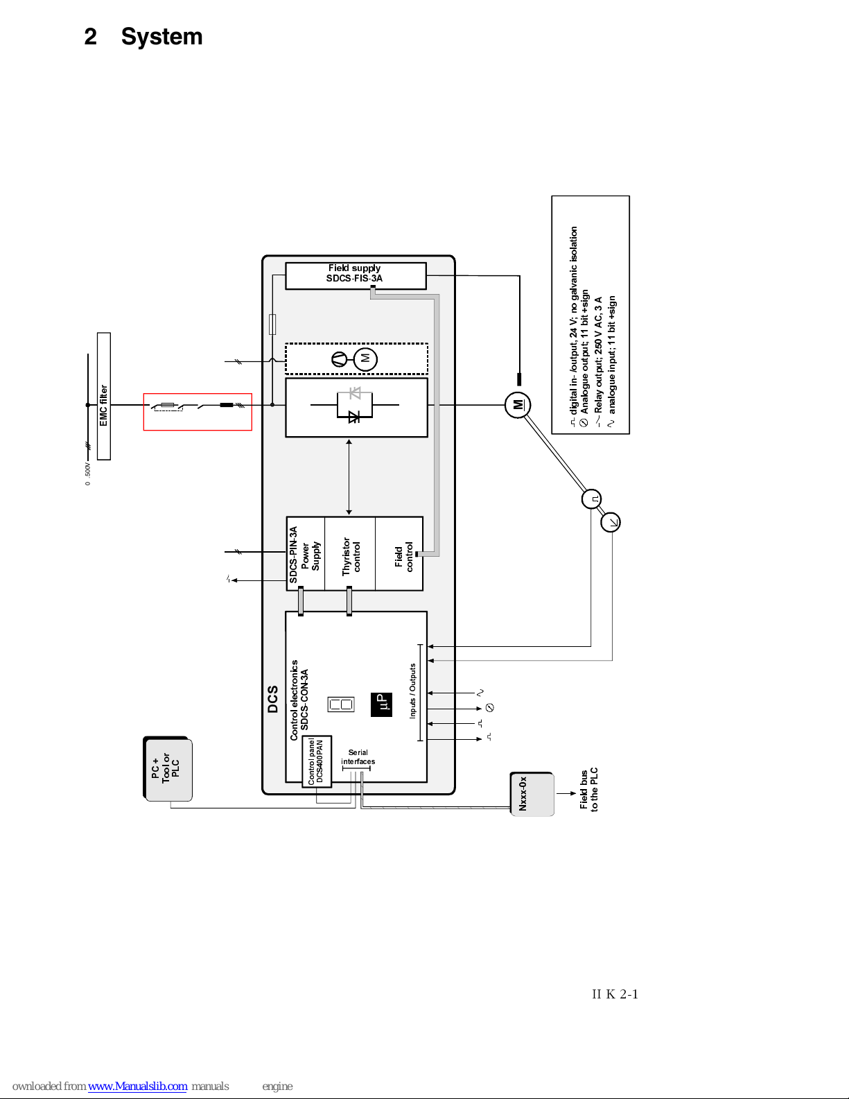
System overview of DCS 400
Safety for Power
conversion Equipment
≤600 V
Standard for module
UL 508 C
Industrial control
Equipment: industrial
products ≤600 V
CSA C 22.2. No.1495