Atomic 45-6666W/F User manual

888-996-2729-1
1353-378-668-1:XAF
moc.stropsedalacse@gameroom
ytilauqtsehgihehtfoerastcudorpruotahterusneotevirtseW
fi,revewoH.strapgnissimrostcefedgnirutcafunamfoe
erfdna
,tcudorpwenruoyhtiwsmelborpynaevahuoy
EROTSEHTOTTINRUTERTONOD ,
:@eerfllotsutcatnocesaelp
:otetirwrO
stropSedalacsE
tnemtrapeDecivreSremotsuC
988xoB.O.P
60774NI,ellivsnavE
date code (if,rebmunledomruoyedivorpesaelpstropSedalacsEgnitcatnocnehW
erasrebmunesehT.traptnemecalp
eragnitseuqerfirebmuntrapdna,)elbacilppa
.launamsrenwosihtnidna,gnigakcap,tcudorpehtnodetacol
rebmuNledoMruoY
.straptuobagniriuqninehwdate coderuoyevahesaelP
45-6666W/F
Date Code: 2 - 45-6666W/F - - HL
Purchase Date:
PLEASE RETAIN THIS INSTRUCTION MANUAL FOR FUTURE REFERENCE
1

Make sure you understand the following tips before you begin to assemble your hockey table.
1. Start all bolts by hand before tightening.
2. Some drawings or images in this manual may not look exactly like your product. Please
read and understand the text before starting each assembly step.
TWO ADULTS ARE REQUIRED TO ASSEMBLE
This Full Strength 4 player LED Air Hockey Table
Assembly Tips
Tools Required:
READ AND FOLLOW ALL ASSEMBLY, OPERATION, AND
SAFETY INSTRUCTIONS CAREFULLY. AT LEAST TWO
ADULTS ARE NEEDED TO PUT THIS HOCKEY TABLE
TOGETHER.
T1 - Allen Wrench (Included)
IMPORTANT! READ EACH STEP
IN THIS MANUAL BEFORE YOU
BEGIN THE ASSEMBLY.
Phillips Screwdriver
Furniture Polish and Cloth
2
ATTENTION:

1. Read all instructions-All the safety and operating instructions should be read carefully before the hockey game is
played.
2. Caution-This is not a toy and is intended for use by or under the supervision of adults. Adults should review
safety guidelines with children to avoid possible risk of electric shock or other injuries.
3. Power sources-This hockey game should be operated only from 110-120V A.C., 60 cycle current as indicated on
the identification label. If you are not sure of the type of power supply to your home, consult your appliance dealer
or local power company.
4. Power cord protection-Power cord should be routed so that it is not likely to be walked on or pinched by items
placed upon or against it. Pay particular attention to cords at plugs, convenience receptacles, and the point of
exit from the game.
5. Overloading-Do not overload wall outlets and extension cords as this can result in a risk of fire or electric shock.
6. Object and liquid entry-Never push objects of any kind into this game through openings as they may touch
dangerous voltage points or short-out parts which could result in a fire or electric shock. Never spill liquid of any
kind on the game.
7. Ventilation-Openings in the game are provided for the exhaust air to create a cushion effect. The openings on
the air blower are for the intake air. Keep clear of the air blower when it is on. Do not put hand or other objects
near the intake openings. To ensure reliable operation of the game and protect it from overheating these openings
must not be blocked or covered.
8. Damage requiring service-Unplug the game from the wall outlet.
Do not attempt to service the blower yourself as opening or removing covers may expose you to dangerous
voltage or other hazards. Refer servicing to qualified service personnel under the following conditions.
A. When the power supply cord or plug is damaged.
B. If liquid has spilled, or objects have fallen into the blower.
C. When the air blower exhibits a distinct change in performance e.g. abnormal noise, this indicates a need for
service.
9. CAUTION-ELECTRICALLY OPERATED PRODUCT-Not recommended for children
under 8 years of age. As with all electrical products, precautions should be observed
during handling and use to reduce the risk of electric shock.
10. We recommend that the game be periodically examined for conditions that may result in the risk of fire, electrical
shock, or injury to persons. In the event such conditions exist, the game should not be used until properly
repaired.
11. RISK OF FIRE, ELECTRIC SHOCK, OR INJURY TO PERSONS
WARNING-When using electric appliances, basic precautions should always be followed, including the following:
A) Read all the instructions before using the appliances.
B) To reduce the risk of injury, close supervision is necessary when an appliance is used near children.
C) Do not contact moving parts.
D) Only use attachment recommended or sold by the manufacturer.
E) Do not use outdoors.
F) For a cord-connected appliance, the following shall be included:
-To disconnect, turn all controls to the off position, then remove plug from outlet.
-Do not unplug by pulling on cord. To unplug, grasp the plug, not the cord.
-Unplug from outlet when not in use and before servicing or cleaning.
-Do not operate any appliance with a damaged cord or plug, or after the appliance malfunctions or is dropped or
damaged in any manner. Stop using this product and call our customer service department for a replacement part.
SAVE THESE INSTRUCTIONS
WARNING: To Reduce The Risk Of Fire Or Electric Shock, Do Not Use This Fan With Any
Solid-State Speed Control Device.
For Household use only.
IMPORTANT SAFETY INSTRUCTIONS
READ ALL INSTRUCTIONS
3

HARDWARE IDENTIFIER
(To Scale)
H1 - 6 mm x 35 mm
Allen Head Bolt
(16 pcs)
H2 - 6.3 mm x 16 mm
Flat Washer
(16 pcs)
H3 - 3.5 mm x 14 mm
Phillips Round
Head Screw
(48pcs)
(Not to Scale)
T1 - Allen Wrench
(1 pc)
(80 pcs)
- 4 mm x 40 mm
Phillips Flat
Head Screw
H4
ACCESSORIES IDENTIFIER
(Not to Scale)
(4 pcs) (2 pcs)
-Red LED StrikerA1 -Red Puck
A2
(2 pcs)
-Red LED PuckA3 A4- Felt Pad
(4 pcs)
4
A5-USB Cable
(2 pcs)
A6-Goal Box Puck
Blocker Insert
(2 pcs)
A7-A/C Adapter
(1 pc)
Used to charge A1 Strikers only
NOTE: A4 Felt Pads may already
Note: used to covert 4-player
game to 3-player or 2-player game
be attached to A1 Strikers.

P6- End Leg Panel
(Atomic logo) (Full Strength logo)
2 pcs
P7- End Leg Panel
2 pcs
P8- Leg Bottom Board
PARTS IDENTIFIER
(Not to Scale)
P1 - Air Hockey Cabinet
with 2 DC Fan motors
(1 pc)
P2 - Left Leg panel
(4pcs)
P3 - Right Leg panel
(4 pcs)
(4 pcs)
P9- Leg Attaching Board P10-Hinge
Factory Installed on all P6
and P7 End Leg Panels
(4 pcs)
P4 - Front Leg panel
(4pcs)
P5 - Back Leg panel
(4 pcs)
(16 pcs)
P11- Goal Box with Sensors
and Connecting Wires
(4 pcs)
5
With P-10 factory installed hinges With P-10 factory installed hinges

6
STEP 1:
48 pcs - H4 4 X 40mm Phillips Flat Head Screw 4 pcs - P2 Left Leg panel
4 pcs - P3 Right Leg panel 4 pcs - P4 Front Leg panel 4 pcs - P5 Back Leg panel
PARTS REQUIRED:
Install one Left Leg Panel P2 and one Right Leg panel P3 onto the edges of one Front Leg Panel P4
using Screws H4 as shown in Figure A-1 and Figure A-2.
Install one Back Leg panel P5 onto the edges of one Left Leg Panel P2 and one Right Leg panel P3
using Screws H4 as shown in Figure B.
TIGHTEN, BUT DO NOT STRIP OUT SCREWS.
Repeat procedure for the other 3 legs.
IMPORTANT NOTE: INSTALL P2 LEFT, P3 RIGHT, P4 FRONT
AND P5 BACK LEG PANELS WITH ALL ARROWS POINTING
SAME DIRECTION AS SHOWN.
Helpful Hint: Each leg (of 4 pcs) is packed separately in 4 cartons.
Figure A-1 Figure A-2 Figure B
P3
Raw wood up
Raw wood up
Raw wood up
P2
Mitered edge
H4 H4
P4 P4
Arrows Pointing
on this side
Arrows must be
as per diagram.
Arrow Pointing
on this side
P2
P3
P5
P4
P3
P2
Helpful Hint: place partial leg assembly
open side up and install P5 by shooting
Screws H4 straight down.

P5
P3
H4
H4
P8
P9 Counter sink holes
this side
7
STEP 2:
32 pcs - H4 4 X 40mm Phillips Flat Head Screw
4 pcs - P8 Leg Bottom Board4 pcs - P9 Leg Attaching Board
PARTS REQUIRED:
Install Leg Attaching Boards P9 onto each assembled Leg using Phillips Flat Head Screws H4 as
shown in Figure C.
Install Leg Bottom Boards P8 onto each assembled Leg using Phillips Flat Head Screws H4 as
shown in Figure C.
TIGHTEN, BUT DO NOT STRIP OUT SCREWS.
Repeat procedure for the other 3 legs.
16 pcs - H1 6 X 35mm Allen Head Bolt
16 pcs - H2 6.3 X 16mm Flat Washer 1 pc - T1 Allen Wrench
1 pc - P1 Air Hockey Cabinet
STEP 3:
Install each Leg assembly onto Air Hockey Cabinet P1 using four Allen Head Bolts H1 with Four
Flat Washers H2 as shown in FIGURE D.
DO NOT TIGHTEN H1 BOLTS ON THIS TIME.
Repeat procedure for the other Legs.
See IMPORTANT NOTE below.
NOTE: Counter sink holes this
side. Tighten screws slightly in
board into P8 holes, so screw
heads do not scratch your floor.
Figure C
Figure D
H1
H2
NOTE: Pilot holes to inside
of legs. And legs angle outward.
NOTE: ARROWS POINTING ON THE
LEG PANELS POINT TOWARD LEG
SUPPORT BOARD P9.

P6
P6
P6
P7
P7
P7
P10
P5
P10
P10
P10
H3
H3 H3
H3
8
TIGHTEN, BUT DO NOT STRIP OUT SCREWS.
Lastly, tighten all leg attaching Bolts H1 in STEP 3 using the T1 Allen Wrench.
STEP 4:
With the help of another adult, place and hold each End Leg Panel (Atomic logo) P6 or End Leg Panel
(Full Strength logo) P7 centered and in correct position onto each leg. Install the pre-installed hinges
on Back Leg Panel P5 using pilot holes with Screws H3 as shown in FIGURE E and DETAIL 1.
32 pcs - H3 3.5 X 14mm Phillips Round Head Screw
2 pcs - P6 End Leg Panel (Atomic logo) 2 pcs - P7 End Leg Panel (Full Strength logo)
PARTS REQUIRED:
IMPORTANT NOTE: It may be
necessary to slightly move
the legs in order to achieve
correct placement of the P7
and P8 End Leg Panels in
STEP 4 and Figure E.
NOTE: All End Leg Panels logos
will be upside down and must face
outward for this assembly step.
Caution: Do not step on table during
this assembly step.
DETAIL 1
Figure E
NOTE:Two End Leg Panels (Atomic logo) P6
are opposite to each other. Two End Leg
Panels (Full Strength logo) P7 are opposite
to each other.
use pilot holes
Note: A/C
adapter plugs
in here
Note: While table is upside down, check all electrical
connections and confirm they are all tight.

P11
P11
Goal Box
P11
P11
P11
H3 H3
H3
H3
9
TIGHTEN, BUT DO NOT STRIP OUT SCREWS.
STEP 5:
First, feed the female plug of each Goal Box with Sensors and connecting wires P11 through the hole
on each side apron as shown in DETAIL 2.
Connect the female plug to the male plug near the hole as shown in DETAIL 2 and DETAIL 3.
Lastly, secure Goal Box P11 onto Air Hockey Cabinet P1 using pilot holes with Phillips Round Head
Screws H3 as shown in FIGURE F.
16 pcs - H3 3.5 X 14mm Phillips Round Head Screw
4 pcs - P11 Goal Box with Sensors and Connecting Wires
PARTS REQUIRED:
DETAIL 2
Figure F
DETAIL 3
NOTE:Make sure slots on plugs are turned correctly
for correct installation.DO NOT FORCE THIS
CONNECTION and a flashlight will be very helpful to
study both the male plug and female Plug to insure
a correct connection.

10
CARE AND USE OF YOUR HOCKEY TABLE
.2
rofdednetnisitcudorpsihT ROODNI .ylnoesu
.5 DO NOT
DO NOT
DO NOT
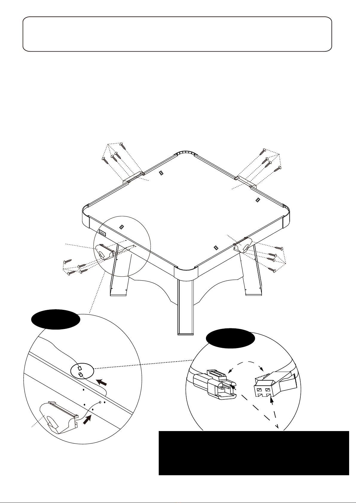
It is suggested that this table be placed close to wall thus allowing the air motor
cord to NOT be a trip hazard. Always turn air motor off when table is not in use.
.6
.elbatehtnonaelrobmilc,tis
.7
8.
This will damage the legs..tignivomnehwelbatehtgard
.elbatehtnosknirdtes
For long life and best play from your air hockey table, apply spray furniture polish
to a clean cloth and wipe down the playfield with air motor running to make the
best play and frequently thereafter.
3.
4. DO NOT operate the motor if the cord is damaged in any way.
Congratulations! You have now assembled your Hockey Table. Please note the Care and Use
instructions below to ensure many years of trouble free use of your Hockey Table.
.1
Use only a suitable 120v AC household outlet, and insure the cord is not a trip hazard.
4 Player Air Powered Hockey Game Modes & Rules:
Game Mode 1 (default mode) 2 Player Traditional Hockey
In this game mode, only Player 1 and Player 2 goal boxes are active for scoring. Be sure to insert the
goal box puck blocking inserts into player 3 and 4 goal boxes to keep the puck in play. Its traditional
head to head air hockey game play and each goal scored counts as 1 point. The first person to score
9 goals is the winner. The LED electronic scorer will display the goals you have scored.
Game Mode 2 2 Player Elimination Hockey
In this game mode, only Player 1 and Player 2 goal boxes are active for scoring. Be sure to insert the
goal box puck blocking inserts into player 3 and 4 goal boxes to keep the puck in play. Its Eliminator
style hockey where the rules are simple. Each player gets 3 lives to start the game as indicated on
the LED scoring display. After each goal that gets scored upon you, one life will be deducted from
your LED screen. Once you are down to zero on the LED screen, you have been eliminated from the
game! 2 player elimination mode provides a shorter game length and is ideal for a quick game of 2
player hockey.
ELECTRONIC SCORER OPERATION:
Press the ON / OFF button to turn on the air powered game table. Press the START button to go to
Game mode 1 : 2 player Traditional Hockey game mode. To play this default mode game, Press
the START button again to begin play.
If you would like to play one of the other exciting game modes, simply continuously press the MODE
button after the table is turned on to toggle through the 6 different game modes. Once you have selected
the game mode of your choice, press the START button to begin game play of the game mode selected.
Below is the game mode menu and game rules for each:
GAME MODE MENU LIST
1, 2 Player Traditional Hockey
2, 2 Player Elimination Hockey
3, 3 Player Elimination Hockey
4, 4 Player Elimination Hockey
5, 4 Player Team Play Traditional Hockey
6, 4 Player Team Play Elimination Hockey
LED will show “0” in the player 1 and player 2 location
LED will show “3” in the player 1 and player 2 location
LED will show “3” in the player 1, 2, and 3 player location
LED will show “3” in all 4 player locations
LED will show “0” in all 4 player locations
LED will show “3” in all 4 player locations

11
Game Mode 3 3 Player Elimination Hockey
In this game mode, Player 1, Player 2, and Player 3 goal boxes are active for scoring. Be sure to insert
the goal box puck blocking inserts into the player 4 goal box to keep the puck in play. Its Eliminator style
hockey where the rules are simple. Each player gets 3 lives to start the game as indicated on the LED
scoring display. After each goal that gets scored upon you, one life will be deducted from your LED
screen. Once you are down to zero on the LED screen, you have been eliminated from the game!
3 player elimination mode provides an awesome multiplayer option for when you have extra players
present and prevents the extra player from sitting out.
Game Mode 4 4 Player Elimination Hockey
In this game mode, all four goal boxes are active for scoring. Its fast and furious 4 player action! Its
Eliminator style hockey where the rules are simple. Each player gets 3 lives to start the game as
indicated on the LED scoring display. After each goal that gets scored upon you, one life will be
deducted from your LED screen. Once you are down to zero on the LED screen, you have been
eliminated from the game! 4 player elimination mode provides an awesome multiplayer option where
everyone gets to play!
Important Note: when 2 players are eliminated. When only 2 players are left playing, one player
will be shifted over to the adjacent goal box for head to head game play directly across from
the other player to continue the final showdown of the game until a winner is determined. The
Led score will automatically shift over to the correct goal box when 2 players are remaining.
The player with the lower score of the two remaining players will be the designated player to
move over one goal box for the direct straightforward head to head competition across from
one another.
Game Mode 5 TEAM PLAY - Traditional Hockey
Teamwork is key to success in TEAM PLAY game mode. Its 4-player style game play but scores from
two players will get combined into one shared team score. Players 1 and 3 are on the same team and
will share and combine goals made. Players 2 and 4 are on the same team and will share and combine
goals scored. Traditional hockey rules apply so the first “team” to score 9 goals is the winning team!
You can choose to play this team play mode with only 3 players and have a 2 player versus 1 player
matchup by simply inserting the puck blocker into the goal box not being used.
Game Mode 6 TEAM PLAY – Elimination Hockey
Teamwork is key to success in TEAM PLAY game mode. Its Elimination style game play where each
TEAM starts out with 3 lives per TEAM as indicated on the LED display. Players 1 and 3 are on the
same team and will get 3 lives in total and will be equally penalized a life if one of the players gives up
a goal. Players 2 and 4 are on the same team and will follow the same rules as above. The first “team “
to lose all lives will be eliminated. You can choose to play this team play mode with only 3 players and
have a 2 player versus 1 player matchup by simply inserting the puck blocker into the goal box not
being used.
SAFE ZONE SAFETY RULES:
You will see the word “SAFE ZONE” printed in 4 locations on the playfield inside a striped border
for each players location. It is strongly recommended for the safety of the players to keep your
pusher strikers within the printed lines or the safe zone to avoid colliding strikers with the other
players.
CAUTION: Adult supervision is recommended at all times. Please read the following and make
sure all players comply with the below instructions during game play:
The Full Strength hockey playfield provides exciting multiplayer action with the unique experience
of allowing 4 players to all play at one time. For the best gaming experience and the overall safety
of the players, its extremely important that reasonable common sense is used when striking the
puck. Because the players are closer together than traditional air power hockey, it’s important
not to strike the puck with extreme and aggressive force. Excessive and overly aggressive striking
of the puck can cause the puck to elevate off of the table and cause potential harm.

12
ELECTRICAL CONNECTIONS & SPARE PARTS DRAWINGS
P11 Goal Box with sensors
P11 Goal Box
with sensors
P11 Goal Box with sensors
C6 Digit Display-Player 1
C9 Digit Display-Player 4
C7 Digit Display-Player 2
C8 Digit
Display
- Player 3
C1 Control Box
C5 Air Motor
C4 Air Motor Junction Box
C3 Main Junction Box
C10 Motor Wiring - 0.9m
C11 Motor Wiring - 0.4m
C13 Goal Box Wiring - 0.7m
C14 Goal Box Wiring - 1.8m
C12 Motor Wiring - 0.65m
C13 Goal Box Wiring - 0.7m
P11
Goal Box
with sensors
POWER
SENSOR / PLAYER
HLY827
CONTROL DISPLAY4 DISPLAY2
DISPLAY3 DISPLAY1 FAN
4 2 3 1
C13 Goal Box Wiring - player 1
C15 Goal Box Wiring - player 3
C14 Goal Box Wiring - player 2
C12 Motor Wiring - 0.65m
C16 Goal Box Wiring - player 4
A7 A/C Adapter

13
PRODUCT PARTS LIST
45-6666HLH1
6 x 35 mm Allen Head Bolt
Main Junction Box
45-6666HL
C1 Control Box 1
45-6666HL
C3 1
1
1
45-6666HL
C4 Air Motor Junction Box
2
45-6666HL
C5 Air Motor
45-6666HL
C6 Digit Dispaly-Player 1
1
1
1
45-6666HL
C7 Digit Dispaly-Player 2
45-6666HL
C8 Digit Dispaly-Player 3
45-6666HL
C9 Digit Dispaly-Player 4
1
1
1
45-6666HL
C10 Motor Wiring-0.9m
45-6666HL
C11 Motor Wiring-0.4m
45-6666HL
C12 Motor Wiring-0.65m
1
1
45-6666HL
C13 Goal Box Wiring-player 1
45-6666HL
C14 Goal Box Wiring-player 2
1
1
45-6666HL
C15 Goal Box Wiring-player 3
45-6666HL
C16 Goal Box Wiring-player 4
16
45-6666HLH2
6.5 x 16 mm Flat Washer
16
45-6666HLH3
3.5 x 14 mm Phillips Round Head Screw
48
45-6666HLH4
4 x 40 mm Phillips Flat Head Screw
80
45-6666HLT1
Allen Wrench
1
45-6666HLA1
Red LED Striker
4
45-6666HLA2
Red Puck
2
45-6666HLA3
Red LED Puck
2
45-6666HLA4
Felt Pad
4
45-6666HLA5
USB Cable
2
45-6666HLA6
Goal Box Puck Blocker Insert
2
45-6666HLA7
A/C Adapter 1
45-6666HLP1
Air Hockey Cabinet with 2 DC fan motors
1
45-6666HLP2
Left Leg Panel 4
45-6666HLP3
Right Leg Panel 4
45-6666HLP4
Front Leg Panel 4
45-6666HLP5
Back Leg Panel 4
45-6666HLP6
End Leg Panel (Atomic logo)
2
45-6666HLP7
End Leg Panel (Full Strength logo)
2
45-6666HLP8
Leg Bottom Board
4
45-6666HLP9
Leg Attaching Board
4
45-6666HLP10
Hinge 16
45-6666HLP11
Goal Box with Sensors and Connecting wires 4
Part#
Description Qty Part# Description Qty
MODEL: 45-6666
This device complies with Part 15 of the FCC Rules. Operation
is subject to the following two conditions:
(1) this device may not cause harmful interference, and
(2) this device must accept any interference received, including
interference that may cause undesired operation

14
LED PUCK BATTERY CHANGE INSTRUCTION
STEP ONE:
Remove screws and back
cap from LED Puck using Small
Phillips Screwdriver (not provided).
STEP TWO:
Remove CR2016 Lithium
Battery 3V from LED Puck.
STEP THREE:
Insert new CR2016 Lithium Battery 3V
into LED Puck.
STEP FOUR:
Install back cap and secure screws with Phillps Screwdriver
(not provided).
Positive “+”
on bottom
side
LED STRIKER BATTERY CHARGE INSTRUCTION
NOTE:
Make sure the on/off
switch on the back
cap properly aligns
and fits into its slot in
the LED puck during
reassembly
IF BATTERY HOLDER BRACKET
MOVES, RE-INSTALL IT TO LED
PUCK AS SHOWN IN DIAGRAM.
USB Port
LED INDICATOR WILL LIGHT-UP DURING CHARGING AND
WILL TURN OFF WHEN ITS FULLY CHARGED.
Helpful Hint:
The LED puck battery will last approximately 7 hours of continuous play. The puck battery is not
rechargeable. Be sure to turn the switch to the “OFF” position when not in use to conserve your
battery life.
Helpful Hint:
The LED strikers each will require about 4 hours to fully charge up and will last approximately
7 hours of continuous play time. Be sure to turn the switch to the “OFF” position when not in use.

15
y ESCALADEnafoesahcrupehtno,renwolanigiroehtotsdnetxeytnarrawremotsucsihT
.)"tcudorP"ehtsaderreferretfaniereh(tcudorPSTROPS
:NOITARUDYTNARRAW 09fodoireparof,renwolanigiroehtotdetnarrawsitcudorPsihT
.esahcruplanigiroehtmorfsyad
:EGAREVOCYTNARRAW tcudorpsiht,renwolanigiroehtotstnarrawSTROPSEDALACSE
esoprupdednetniehtrofdesunehwpihsnamkrowdnalairetamnistcefedmorfeerfebot
NEEBSAHTCUDORPEHTFIDIOVSIYTNARRAWSIHT.snoiti
dnocdnaesulamronrednu
,ECIVRESREPORPMI,ECNEGILGEN,ESUELBANOSAERNU,TNEDICCAYBDEGAMAD
REHTOROTCUDORPEHTHTIWDEDIVORPSNOITCURTSNIWOLLOFOTERULIAF
.PIHSNAMKROWDNALAIRETAMNISTCEFEDFOTUOGNISIRATONSESUAC
:TNEMECALPERYTNARRAW ,doirepytnarrawyad09evobaehtgniruD
elbarapmocahtiwecalperrostnenopmoctnemecalperedivorpllahsSTROPSEDALACSE
esaelp,eracreporpdnaesulamronrednuevitcefedsitcudorpfI.gnisoohcruotatcudorp
.tpeDeciv
reSremotsuCruotcatnoc
.tpeDecivreSremotsuC/888-996-2729-1
:tasuetirWrO
60774NI,ellivsnavE,988xoB.O.P-.cnI,stropS®edalacsE
.tpeDecivreSremotsuC:nttA
:tasuliam-ErO
moc.stropsedalacse@gameroom
Other than shipping requirements, no charge will be made for such replacement of in-warranty
products.
:SREMIALCSIDYTNARRAW TUOGNISIRASEITNARRAWDEILPMIYNA
SEITNARRAWDEILPMIEHTOTDETIMILTONTUBGNIDULCNI,ELASSIHTFO
ERA,ESOPRUPRALUCITRAPAROFSSENTIFDNAYTILIBATNAHCREMFO
TROPSEDALACSE.DOIREPYAD09EVOBAEHTOTNOITARUDNIDETIMIL S
REHTOROTCUDORPEHTFOESU
FOSSOLROFELBAILEBTONLLAHS
SEGAMADROSESNEPXE,STSOCLATNEDICNIROLAITNEUQESNOC
.ESUREHTOYNAFOREMUSNOCEHTYBDERRUCNI
rolaitneuqesnocroseitnarrawdeilpmifonoitatimilronoisulcxeehtwollatonodsetatsemoS
.uoyotylppatonyamsnoisulcxerosnoitatimilevobaehtos,segamadlatnedicni
:SEIDEMERLAGEL evahoslayamuoydnasthgirlagelcificepsuoysevigytnarrawsihT
.etatsotetatsmorfyravyamhcihwsthgirrehto
YTNARRAWDETIMILYAD09

1
,
:
1-888-996-2729
: 1-866-873-3531
:
Escalade Sports
Veuillez vous rendre sur notre site Web :
P.O. Box 889
Evansville, IN 47706
VEUILLEZ CONSERVER CE MANUEL D'INSTRUCTIONS POUR CONSULTATION FUTURE
45-6666W/F
:
:
:
45-6666W/F-
-HL

2
IMPORTANT!
COMMENCER L'ASSEMBLAGE.
Outils nécessaires:
Clé Allen T1 (incluse)
Tournevis Phillips
Cire pour meubles tissu
Un tournevis électrique peut faciliter l'assemblage. Toutefois, veillez à le régler sur un
couple réduit et faites preuve d'une extrême prudence lors de l'utilisation du tournevis
électrique parce que vous pourriez serrer excessivement le matériel et faire foirer les vis.
table à abattant.
Conseils d'assemblage
LIRE ET SUIVRE ATTENTIVEMENT LES
INSTRUCTIONS D'ASSEMBLAGE, D'UTILISATION ET
DE SÉCURITÉ. L'ASSEMBLAGE DE CETTE TABLE DE
1. Introduire tous les boulons à la main avant de les serrer.
2. Certains dessins ou images dans ce manuel peuvent être différents de votre produit. Veuillez
lire et comprendre le texte avant de commencer chaque étape d'assemblage.
AVERTISSEMENT
LES DESSINS DE CE MANUEL
PEUVENT ÊTRE EXAGÉRÉS
OU MODIFIÉS POUR MONTRER
DES DÉTAILS.
DEUX ADULTES SONT RECOMMANDÉS POUR ASSEMBLER
Cette table complète de hockey pneumatique DEL à 4 joueurs

1. Lire toutes les instructions – Vous devez lire attentivement toutes les instructions d'utilisation et de sécurité avant de joueur
au jeu de hockey.
2. Mise en garde-Ceci n'est pas un jouet. L'utilisation de ce jeu doit se faire par des adultes ou sous leur supervision. Les
adultes doivent réviser les directives de sécurité avec les enfants pour éviter le risque d'étouffement ou d'autres blessures.
3. Sources d'alimentation-Ce jeu de hockey doit être branché uniquement à une source de 110-120 V CA de 60 cycles,
comme indiqué sur l'étiquette d'identification. Si vous n'êtes pas sûr du type d'alimentation électrique de votre maison,
consultez votre concessionnaire d'appareils électroménagers ou votre compagnie d'électricité locale.
4. Protection du câble d'alimentation-Le câble d'alimentation doit être acheminé de telle sorte qu'il ne soit pas piété ou pincé
par les éléments placés sur ou contre lui. Accordez une attention particulière aux cordons au niveau des prises, aux fiches de
connexion et au point de sortie du jeu.
5. Surcharge-Ne surchargez pas les prises de courant murales et les cordons d'extension, car cela peut provoquer un incendie
ou un choc électrique.
6. Entrée des objets et liquides-N'introduisez aucun objet de quelque sorte que ce soit dans ce jeu à travers les ouvertures car
ils peuvent toucher des points de tension ou des parties de court-circuit dangereux, ce qui peut provoquer un incendie ou un
choc électrique. Ne déversez aucun liquide sur le jeu.
7. Ventilation-Des ouvertures sont fournies sur le jeu pour évacuer l'air et créer un effet d'amortissement. Les ouvertures sur
la souffleuse d'air sont pour l'air d'admission. Tenez-vous à l'écart de la souffleuse d'air lorsqu'elle est allumée. Ne mettez
pas votre main ou d'autres objets à côté des ouvertures d'admission pour assurer un fonctionnement fiable du jeu et le
protéger de la surchauffe, ne bloquez pas ces ouvertures et ne les couvrez pas.
8. Dommages nécessitant une réparation-Débranchez le jeu de la prise murale.
N'essayez pas de réparer la souffleuse d'air vous-même, car ouvrir ou retirer les couvercles peut vous exposer à une tension
dangereuse ou à d'autres dangers. Confiez les réparations à un personnel d'entretien qualifié quand les conditions suivantes
surviennent.
A. Lorsque le cordon ou la prise d'alimentation sont endommagés.
B. Si un liquide a été déversé ou que des objets sont tombés dans la souffleuse d'air.
C. Quand la souffleuse d'air présente un changement de fonctionnement important, par exemple un bruit anormal, cela indique
un besoin d'entretien.
9. MISE EN GARDE-PRODUIT ÉLECTRIQUE. Non recommandé pour les enfants-de moins de 8 ans. Comme c'est le cas
avec tous les produits électriques, des précautions doivent être observées lors de la manutention et de l'utilisation
de ce produit pour réduire le risque choc électrique.
10. Nous recommandons d'examiner périodiquement le jeu pour vérifier l'absence de problèmes pouvant entraîner un risque
d'incendie, de choc électrique ou de blessures corporelles. Si de tels problèmes existent, le jeu ne doit pas être utilisé avant
qu'il ne soit correctement réparé.
11.RISQUE D'INCENDIE, DE CHOC ÉLECTRIQUE OU DE BLESSURES CORPORELLES
AVERTISSEMENT-Lors de l'utilisation des appareils électriques, des précautions de base doivent toujours être observées, notamment :
A) Lire toutes les instructions avant d'utiliser ces appareils.
B) Pour réduire le risque de blessure, une supervision étroite est nécessaire quand l'appareil est utilisé près des enfants.
C) Ne pas toucher les pièces mobiles.
D) N'utiliser que la fixation recommandée ou vendue par le fabricant.
E) Ne pas utiliser l'appareil à l'extérieur.
F) Pour les appareils branchés à un cordon électrique, les instructions suivantes doivent être incluses :
-Pour débrancher l'appareil, désactiver toutes les commandes, puis retirer la fiche de la prise.
-Ne pas débrancher en tirant sur la corde. Pour débrancher l'appareil, saisir la fiche, non le cordon.
-Débrancher l'appareil de la prise lorsqu'il n'est pas utilisé et avant l'entretien ou le nettoyage.
-N'utiliser aucun appareil avec un cordon ou une prise endommagés, ou après un dysfonctionnement de l'appareil, ou si
celui-ci est tombé ou a été endommagé de quelque façon que ce soit. Arrêtez d'utiliser ce produit et appelez notre Service à
la clientèle pour obtenir une pièce de remplacement.
INSTRUCTIONS DE SÉCURITÉ IMPORTANTES
LIRE TOUTES LES INSTRUCTIONS
CONSERVER CES INSTRUCTIONS
AVERTISSEMENT : Pour réduire le risque d'incendie ou de choc électrique, n'utilisez pas ce
ventilateur avec un dispositif de commande de la vitesse à semi-conducteurs.
Destiné uniquement à l'usage ménager.
3

IDENTIFICATION DU MATÉRIEL
(à l'échelle)
H1 - 6 mm x 35 mm
Boulon à tête Allen
(16 pcs)
H2 - 6.3 mm x 16 mm
Rondelle plate
(16 pcs)
H3 - 3.5 mm x 14 mm
Vis à tête
bombée Phillips
(48 pcs)
(non à l'échelle )
T1 - Clé Allen
(1 pc)
(80 pcs)
- 4 mm x 40 mm
Vis à tête
plate Phillips
H4
IDENTIFICATION DES ACCESSOIRES
(non à l'échelle)
(4 pcs)(2 pcs)
-Bâton DEL rougeA1 -Rondelle rouge
A2
(2
pcs
)
-Rondelle DEL rougeA3 A4- Patin en feutre
(4 pcs)
4
A5-Câble USB
(2 pcs)
A6-Insert de bloqueur
de rondelle de cage de but
(2 pcs)
A7-Adaptateur CC
(1 pc)
Utilisé pour charger les
bâtons A1 seulement
REMARQUE : Les patins A4 en feutre
peuvent déjà être fixés aux bâtons A1
Note: used to covert 4-player
game to 3-player or 2-player game

P6- Panneau de pied
d'extrémité (logo Atomic)
(2 pcs)
P7- Panneau de pied
d'extrémité (logo au complet)
(2 pcs)
P8- Panneau inférieur
de pied
IDENTIFICATION DES PIÈCES
(non à l'échelle)
P1 - Meuble de hockey
pneumatique avec 2 moteurs
de ventilateur CC
(1 pc)
P2 - Panneau de
pied gauche
(4 pcs)
P3 - Panneau de
pied droit
(4 pcs)
(4 pcs)
P9- Panneau de fixation
de pied
P10-Charnière
installée en usine sur tous les
panneaux de pied d'extrémité P6 et P7
(4 pcs)
P4 - Panneau de
pied avant
(4 pcs)
P5 - Panneau de
pied arrière
(4 pcs)
(16 pcs)
P11- Cage de but avec
capteurs et fils de connexion
(4 pcs)
5
Avec des charnières P10
installées en usine
Avec des charnières P10
installées en usine
Table of contents
Languages:
Other Atomic Indoor Furnishing manuals
Popular Indoor Furnishing manuals by other brands

Moebelix
Moebelix E-Landwood 43 Assembly instructions

COASTLINE
COASTLINE CAFE FUSION 318 Assembly instructions

Butler
Butler 3930101 Assembly instructions

Safavieh Furniture
Safavieh Furniture HAC1017A quick start guide

Happy Babies
Happy Babies HAPPY RN05 Assembly instructions

Next
Next NEW HENRY 973006 Assembly instructions

Haworth
Haworth Lyft Setup & user guide

Unfinished Furniture of Wilmington
Unfinished Furniture of Wilmington R-52581 Assembly instructions

Kvik
Kvik MH651,060 manual

Hinkle Chair Company
Hinkle Chair Company 400 SLAT ROCKER Assembly instructions

AKANTE
AKANTE RIO DT440 Assembly instructions

Hoshizaki
Hoshizaki Refrigerated Prep Table with Raised Rail instruction manual