Atosa YR140-AP-161 User manual

YR SERIES ICEMAKER END-USER MANUAL
In order to provide the best
service, Atosa requests that
you register your warranty at
www.atosausa.com
For any service issues, please
contact us at:
Email: service@atosausa.com
or call us Toll Free:
1-855-855-0399
Please clean the filter frequently
DO NOT OVERLOAD
Please clean the filter frequently
DO NOT OVERLOAD
YR140-AP-161 / YR280-AP-161 / YR450-AP-161 / YR800-AP-161

1 / 22
Content
I.
Summary ................................................................................................................................... 2
1. Model ................................................................................................................................ 2
2. Ice production ................................................................................................................... 3
II.
Safety Notices............................................................................................................................ 4
III.
Installation ............................................................................................................................. 5
1. Power supply ..................................................................................................................... 5
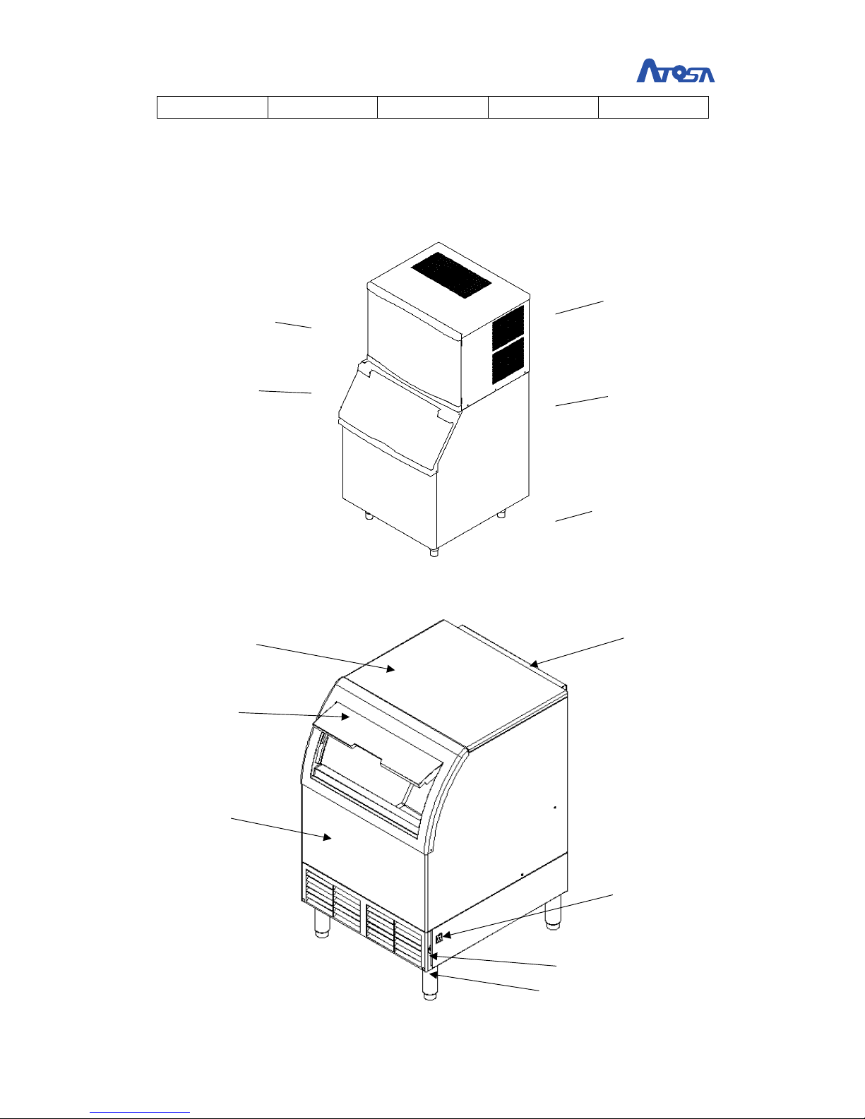
2. Construction ...................................................................................................................... 6
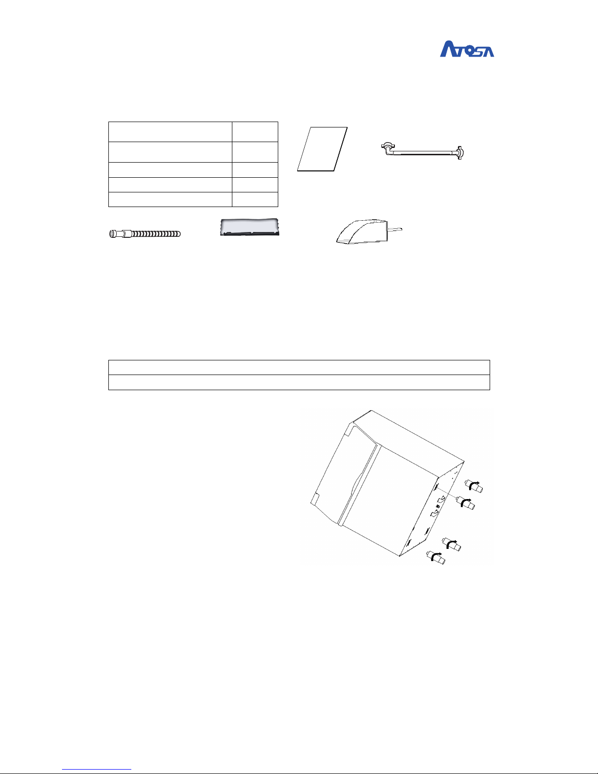
3. Accessories ........................................................................................................................ 7
4. Ice bin installation ............................................................................................................. 7
5. Ice machine head installation ........................................................................................... 7
6. Obstruction panel installation(no in the self-contained machine) ........................... 8
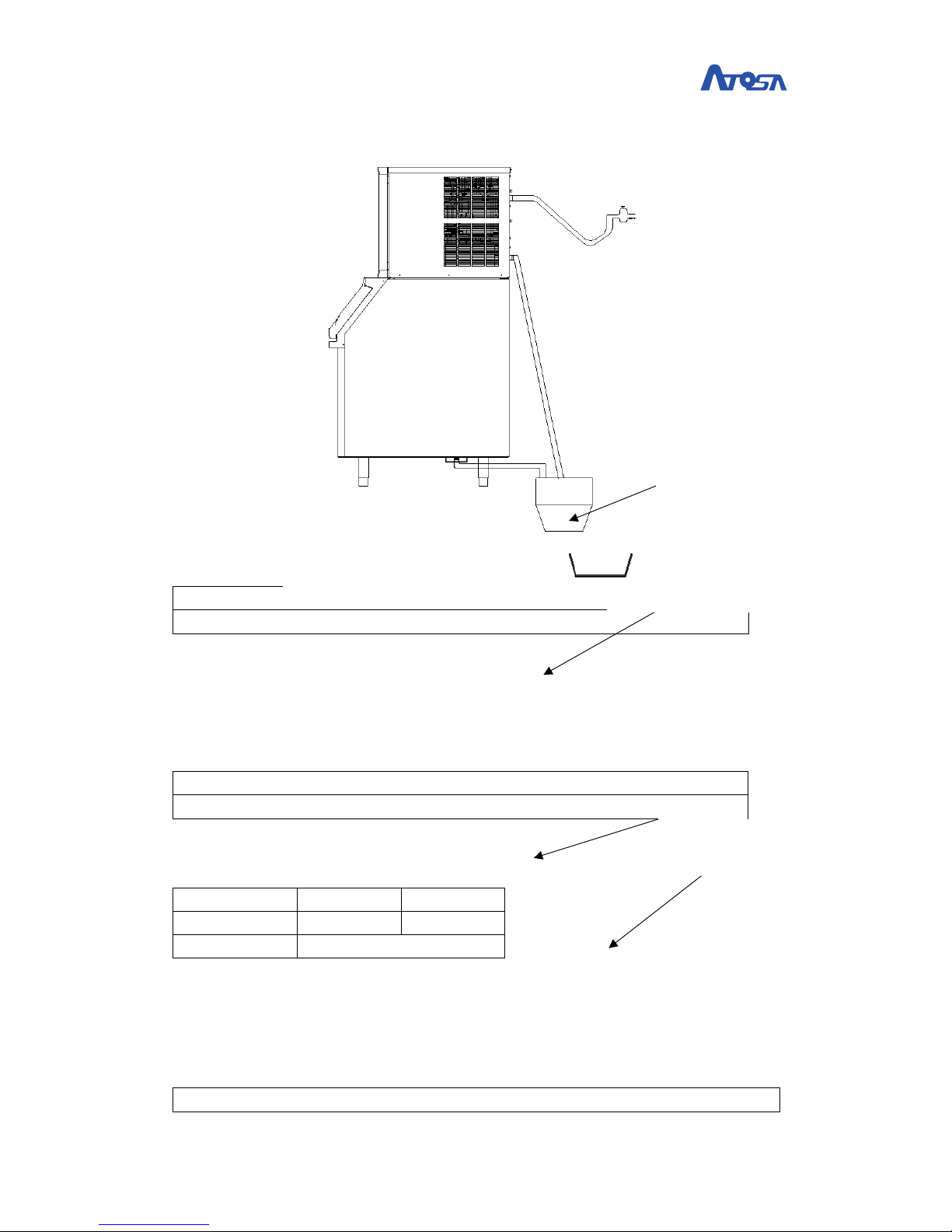
7. Connect the water inlet hose and drain hose ................................................................... 8
8. Installation location ........................................................................................................... 9
IV.
Operation ............................................................................................................................ 10
1. Checklist before operation .............................................................................................. 10
2. operation ......................................................................................................................... 10
3. Ice weight per batch ........................................................................................................ 11
V.
Maintenance ........................................................................................................................... 12
Clean and sanitize ........................................................................................................................... 12
Condenser air-filter wash ........................................................................................................ 15
VI.
Service ................................................................................................................................. 16
1. Diagram ........................................................................................................................... 17
2. Safety protection ............................................................................................................. 17
3. LED indication .................................................................................................................. 17
4. Failures analysis ............................................................................................................... 18
5. Customer Support ........................................................................................................... 19
6. Waste disposal ................................................................................................................ 20
7. Commercial Ice Machine Warranty ................................................................................. 20

2 / 22
I.
Summary
The following data are for reference only
1.
Model
Model
YR140-AP-161
YR280-AP-161
YR450-AP-161
YR800-AP-261
Cooling style
Air
Air
Air
Air
Power supply
110-120V/
60Hz
110-120V/
60Hz
110-120V
/60Hz
220-240V
/60Hz
Power(W)
363
704
965
1700
Max Ice
production(IBS/24hr)
140lb
280lb
450lb
800lb
Dimension(mm)
601*725*981
601*725*981
765*610*557
765*610*801
Weight(kg)
65
70
57
90
Refrigerant
R290/90g
R290/90g
R290/150g
R404a/440g
Using temp. range
2~43℃
2~43℃
2~43℃
2~43℃
Water temp. range
1~32℃
1~32℃
1~32℃
1~32℃
Water pressure range
15~90Psi
15~90Psi
15~90Psi
15~90Psi
Power range
+10%/-15%
+10%/-15%
+10%/-15%
+10%/-15%

3 / 22
2.
Ice production
YR140-AP-161 Ice production
:
Ambient
Temp.
Water
Temp.
Ice production(Ibs/24hr)
70F(21℃)
90F(32℃)
100F(38℃)
70F(21℃)
142
105
90
YR280-AP-161 Ice production
:
Ambient
Temp.
Water
Temp.
Ice production(Ibs/24hr)
70F(21℃)
90F(32℃)
100F(38℃)
70F(21℃)
283
225
201
YR450-AP-161 Ice production
:
Ambient
Temp.
Water
Temp.
Ice production(Ibs/24hr)
70F(21℃)
90F(32℃)
100F(38℃)
70F(21℃)
460
415
385
YR800-AP-261 Ice production
:
Ambient
Temp.
Water
Temp.
Ice production(Ibs/24hr)
70F(21℃)
90F(32℃)
100F(38℃)
70F(21℃)
810
650
550

4 / 22
II.
Safety Notices
Please read this manual carefully before proceeding, otherwise, can result
in death, serious injury or damage to the equipment.
• Caution
* Read this manual thoroughly before operating, installing or performing
maintenance on the equipment. Failure to follow instructions in this manual can
cause property damage, injury or death.
• Notice
* The ice making machine is commercial equipment, which is only suitable for
the proper location,
* The manufacturer shall not be liable for any loss caused by improper operation
or usage.
* Installation and necessary shift work, must be handed over to have the
corresponding knowledge workers in accordance with the local laws and
regulations according to the manufacturer's instructions.
* Proper installation, care and maintenance are essential for maximum
performance and trouble free operation of your equipment.
• Warning
* This equipment contains high voltage electricity and refrigerant charge.
Installation and repairs are to be performed by properly trained technicians
aware of the dangers of dealing with high voltage electricity and refrigerant
under pressure. The technician must also be certified in proper refrigerant
handling and servicing procedures. All lockout and tag out procedures must be
followed when working on this equipment.
* The ice maker is to be installed in accordance with the Safety Standard for
Refrigeration Systems, ASHRAE 15 and shall not be installed in corridors or
hallways of public buildings.
* Component parts shall be replaced with like components and that servicing
shall be done by factory authorized service personnel, so as to minimize the
risk of possible ignition due to incorrect parts or improper service.

5 / 22
III.
Installation
Installation Check List
1, Is the Ice Machine level?
2, Have all of the electrical and water connections been made?
3, Has the supply voltage been tested and checked against the rating on the
nameplate?
4, Is there proper clearance around the ice machine for air circulation?
5, Is the ice machine grounded and polarity correct?
6, Has the ice machine been installed where ambient temperatures will remain
in the range of 35° - 110°F (1.6° - 43.3°C)?
7, Is there a separate drain for the potable water, bin and water-cooled
condenser?
8, Are all electrical leads free from contact with refrigeration lines and moving
equipment?
9, Has the owner/operator been instructed regarding maintenance and the use
of the specified Cleaner and Sanitizer?
10, Has the owner/operator completed the warranty registration card?
11, Has the ice machine and bin been sanitized?
12, Is the ice thickness control set correctly? (Refer to Operational Checks to
check/set the correct ice bridge thickness).
1.
Power supply
• Warning
* All wiring must comply with national and local laws and regulations
* The ice maker must be earthed properly
All electrical operations involved must comply with the following:
1) the ice maker must be grounded;
2) each ice maker must be individually fitted with fuses or breaker;
3) a qualified electrician must be needed with the wires;
4) the ice maker starts with the maximum load and the maximum allowable
voltage fluctuates by +/- 10%;
5) check that the socket is securely fastened before starting.
Match fuse or breaker and machine circuit current
Model
YR140-AP-161
YR280-AP-161
YR450-AP-161
YR800-AP-261
V/P/F
110V/1/60Hz
110V/1/60Hz
110V/1/60Hz
230V/1/60Hz
Fuse/breaker
10A
16A
20A
25A
Min circuit
3.5A
6.8A
9.7A
9.8A

6 / 22
current
2.
Construction
Ice machine head outside view
Self-contained ice machine construction
Front door
Top cove r
Ice bin storage
Right side panel
Bin door
Adjustable foot
Top cove r
door
Back panel
filter
Front panel
Adjustable foot
Switch

7 / 22
3.
Accessories
Use manual
1
Water inlet hose
1
Drain hose
1
Obstruction panel
1
Ice scoop
1
4.
Ice bin installation
• Caution
Adjustive foot must be tightened; otherwise the ice machine will be instable.
1)
2) carefully place the ice bin
storage on the rear side. Then
screw the four adjustable feet
(accessories in the ice bin) into
the four holes at the bottom of
the storage and screw them
down hardly.
3) after the foot is installed, put it
right, and adjust the foot slowly
until the level.
5.
Ice machine head installation
4) carefully remove the machine head paper packaging (do not upside down to
prevent compressor damage), slowly lift the head, placed it on the ice bin
storage .
5) slowly move the ice maker until it is in right place on the ice bin.
User manual
Water inlet hose
Drain hose
Ice scoop
Air baffle(No in
the self-contained
machine)

8 / 22
6.
Obstruction panel installation (no in the self-contained
machine)
• Caution
* Air baffle must be installed, or affect heat reject.
1) Unscrew the two
fixed screws;
2) put the air baffle
as the picture
shows;
7.
Connect the water inlet hose and drain hose
Fixed screws

9 / 22
Ice machine head connection diagram
Self-contained
machine
Water inlet hose
installation
• Notice
The water entering the ice maker must meet the drinking water standard
1) if there is no water filter system, please connect the water inlet hose as
diagram shows;
2) if the water pressure is greater than 80Psi, please install the relief valve
3) if the pressure is less than 20Psi, please install water pressurization;
Drain hose installation
• Notice
the water shall be prevented from flowing into the ice bin storage
4) For the drain hose, each meter long going must have a drop of 2.5 cm。
5) ) the ice bin and the ice machine drains should be separated.
Water inlet
Ambient
Temperature.
1~32℃
2~43℃
Water pressure
30~70Psi
8.
Installation location
• Notice
Water inlet hose
Drain hose
Water inlet hose
Drain hose
The floor drain
The floor drain

10 / 22
Do not put things in the air inlet and outlet of the ice maker to prevent ventilation
and heat reject.
Do not install ice machine in direct sunlight.
1) the ice machine should be installed horizontally;
2) the ambient temperature should be 10~43C(50—110F) and the water inlet
temperature is 1~32 C(33—90F);
3) For the self-contained ice maker:
Left and right side must have at
least 5cm gap from the wall and the
top has 1cm gap.
IV.
Operation
1.
Checklist before operation
a) Is ice machine level?
b) Are Water inlet and drain hose connected ok?
c) If there are not water lack with the ice machine?
d) Check the power voltage, if it matches the label on the machine?
2.
operation
1) Freeze cycle
a) Power plug connection:the control board led is on。
b) startup:Toggle the switch to the on position, the green led will flash; the
hot gas valve open for 10s, the compressor is energized,
c) ice melt: the hot gas valve still keep opening for 20s, then the water
pump running to flush the evaporator for 20s, then close the hot gas
valve and water pump and open the drain valve for 15s then close.
d) prechill(40s):the compressor is on, and the condenser fan and water
inlet valve are energized, hot gas valve and water pump are closed, thus to
Air inlet
Air outlet

11 / 22
prechill the evaporator.
e) Freeze:water pump is energized to make ice in the evaporator.
2) Harvest cycle
f) energy storage:when the harvest probe doesn’t contact the water,
condenser NTC probe test the liquid tube temperature and give the time to
stop the condenser fan before harvest, to add the heat of the refrigeration
system. Increase the harvest effective.
g) Harvest cycle:hot gas valve is energized to heat the evaporator,when
the surface of ice begin to melt, the ice will drop down by the gravity. And
the ice put the water curtain outside and the magnet switch from close to
open to close, harvest cycle ended to return the prechill cycle and start next
step.
h) Ice full:when the magnet switch opens beyond 30s in harvest cycle, the
ice machine stops, mean the ice is full.
3.
Ice weight per batch
YR140-AP-161
YR280-AP-161
YR450-AP-161
YR800-AP-261
Ice Weight per
batch(g)
690—840
860—1050
1650--2000
3100--3750
1) When need to adjust the ice thickness, screws the water probe to change the
water level position. screw the adjustable nut clockwise, increase the ice
thickness; turn the adjustable nut counterclockwise, and reduce the ice
thickness.

12 / 22
V.
Maintenance
Clean and sanitize
Cleaning and Sanitizing GENERAL
You are responsible for maintaining the ice machine in accordance with the instructions in this
manual. Maintenance procedures are not covered by the warranty. Clean and sanitize the ice
machine every three months for efficient operation. If the ice machine requires more frequent
cleaning and sanitizing, consult a qualified service company to test the water quality and
recommend appropriate water treatment. An extremely dirty ice machine must be taken apart for
cleaning and sanitizing.
• Warning
Wear rubber gloves and safety goggles (and/or face shield) when handling Ice Machine
Cleaner or Sanitizer
CLEANING/SANITIZING PROCEDURE
This procedure must be performed a minimum of once every three months.
• The ice machine and bin must be disassembled cleaned and sanitized.
• All ice produced during the cleaning and sanitizing procedures must be discarded.
• Removes mineral deposits from areas or surfaces that are in direct contact with water.
PREVENTATIVE MAINTENANCE CLEANING PROCEDURE
• This procedure cleans all components in the water flow path, and is used to clean the ice machine
between the cleaning/sanitizing procedure.
EXTERIOR CLEANING

13 / 22
Clean the area around the ice machine as often as necessary to maintain cleanliness and efficient
operation.
Wipe surfaces with a damp cloth rinsed in water to remove dust and dirt from the outside of the
ice machine. If a greasy residue persists, use a damp cloth rinsed in a mild dish soap and water
solution. Wipe dry with a clean, soft cloth.
The exterior panels have a clear coating that is stain resistant and easy to clean. Products containing
abrasives will damage the coating and scratch the panels.
• Never use steel wool or abrasive pads for cleaning.
• Never use chlorinated, citrus based or abrasive cleaners on exterior panels and plastic trim pieces.
Cleaning / Sanitizing Procedure
• Warning
Wear rubber gloves and safety goggles (and/or face shield) when handling Ice
Machine Cleaner or Sanitizer.
• Caution
Do not mix Cleaner and Sanitizer solutions together. It is a violation of Federal law to
use these solutions in a manner inconsistent with their labeling
• Caution
Never use anything to force ice from the evaporator. Damage may result.
Ice machine cleaner is used to remove lime scale and mineral deposits. Ice machine sanitizer
disinfects and removes algae and slime. For the cleaner and sanitizer, Ecolab company’s
products, Kay Delimer as the cleaner and kay5 as sanitizer are recommend.
NOTE: Although not required and dependant on your installation, removing the ice machine top
cover may allow easier access.
Step 1 Open the front door to access the evaporator compartment. Ice must not be on the
evaporator during the clean/sanitize cycle. Follow one of the methods below:
• Toggle the switch on “off” position at the end of a harvest cycle after ice falls from the
evaporator(s).
• Toggle the switch on “off” position and allow the ice to melt.
Step 2 Remove all ice from the bin/dispenser.
Step 3 To ggle t he s wi tc h on “c le an” p os it i on . Wa ter wil l f lo w through t he w at e r dum p val v e and
down the drain. Wait until the water trough refills (approximately 1 minute), then add the proper
amount of ice machine cleaner.
Model
Amount of cleaner(Kay delimer)
YR140-AP-161
2 pack
YR280-AP-161
2 pack
YR450-AP-161
4 packs
YR800-AP-261
4 packs
Step 4 Wait until the clean cycle is complete (approximately *30 minutes). Then disconnect power
to the ice machine (and dispenser when used).
Step 5 Remove parts for cleaning. Please refer to the proper parts removal for your ice machine.

14 / 22
Continue with step 6 when the parts have been removed.
Step 6 Mix the cleaner and lukewarm water. Depending upon the amount of mineral buildup, a
larger quantity of solution may be required. Use the ratio in the table below to mix enough solution
to thoroughly clean all parts.
water
Mixed with cleaner
Cleaner solution rate
2L
4 packs
Step 7 Use the cleaner/water mixture to clean all components. use a soft-bristle nylon brush,
sponge or cloth (NOT a wire brush) to carefully clean the parts. Soak parts for 5 minutes (15 - 20
minutes for heavily scaled parts). Rinse all components with clean water.
Step 8 While components are soaking, use the cleaner/water solution to clean all foodzone
surfaces of the ice machine and bin (or dispenser). Use a nylon brush or cloth to thoroughly clean
the following ice.
• Side walls • Base (area above water trough)
• Evaporator plastic parts - including top, bottom, and sides
• Bin or dispenser Rinse all areas thoroughly with clean water
SANITIZING PROCEDURE
Step 9 Mix a solution of sanitizer and lukewarm water
water
Mixed with sanitizer
Sanitizer solution rate
2L
4 packs
Step 10 Use the sanitizer/water solution to sanitize all removed components. Use a spray bottle to
liberally apply the solution to all surfaces of the removed parts or soak the removed parts in the
sanitizer/water solution.
Step 11 Use the sanitizer/water solution to sanitize all foodzone surfaces of the ice machine and
bin (or dispenser). Use a spray bottle to liberally apply the solution. When sanitizing, pay particular
attention to the following areas:
• Side walls
• Base (area above water trough)
• Evaporator plastic parts - including top, bottom and sides
• Bin or dispense,
Step 12 Wait 20 minutes. Do rinse these surfaces with drinking water after sanitizing.
Step 13 Replace all removed components.
Step 14 Reapply power to the ice machine. To gg le the sw itc h o n “c lean” pos ition agai n. Wat e r will
flow through the water dump valve and down the drain. Wait until the water trough refills
(approximately 1 minute), then add the proper amount of ice machine sanitizer
Model
Amount of sanitizer(Kay 5)
YR140-AP-161
1 pack
YR280-AP-161
1 pack
YR450-AP-161
2 packs
YR800-AP-261
2 packs
Use a measuring cup, put in 1L water with the correspondent sanitizer packs with the models,
making the sanitizer solution to add the water trough.
Step 15 After when the sanitizing procedure finished, toggle the switch from clean to on position,
close and secure the front door.

15 / 22
Parts Removal for Cleaning/Sanitizing
For Model YR450-AP-161, YR800-AP-261
1) unscrew the front door
Unscrew the bottom two screws, get away the
front door.
2) remove the water dispense panel
3) remove the water curtain
Unscrew the two thumb screws, remove the
water curtain
4) remove the water trough
For Model YR140-AP-161, YR280-AP-161
1) remove the water curtain
2) Unscrew the two thumb screws, remove the
water curtain
3) remove the water dispense panel
4) remove slides panel
5) remove the water probe stand
6) remove the water trough
Condenser air-filter wash
Remove the air-filter for cleaning.
Thumb screw
Thumb screw

16 / 22
• Notice
Clean air-filter once a month
VI.
Service
• Important
Technicians must have the correlative certificate of service

17 / 22
1.
Diagram
2.
Safety protection
1) E1:Long freeze cycle, freeze cycle reaches 40min for 3 times, stop.
2) E2:Long harvest cycle, harvest cycle reaches 4.5min for 3 times, stop.
3) E3:High pressure protection,discharge pressure reaches 450psi, stop.
4) E4:water lack protection, water probe can’t touch water for 5min in freeze
cycle, stop.
5) E5:condenser temperature alarm, condenser temperature beyond -20~
+80℃not stop,D10 (Led)flash fast.
3.
LED indication
1) D7 green led:ice making indicator
D7 flash slow——1s on 1s off,ice making or ice full;
D7 flash fast——0.2s on 0.2soff,clean procedure end;
D7 Illuminate——clean procedure.

18 / 22
D7 off——switch on “off” position。
2) D8 blue led:water level indicator
D8 flash slow——1s on 1s off,E3,water lack protection.
D8 Illuminate——water probe touch the water
D8 off——water probe not touch the water
3) D9 red led:Harvest cycle indicator/ harvest probe
D9 flash fast——0.3s on 0.3s off,E1,long freeze protection
D9 flash slow——0.7s on 0.7s off, E2,long harvest protection
D9 Illuminate——harvest probe not touch the water
D9 off——harvest probe touch the water
4) D10 yellow led:water curtain switch indicator
D10 flash fast——0.3s on 0.3s off,E4, HP protection
D10 flash slow——1s on 1s off,E5, NTC temperature alarm
D10 Illuminate——water curtain switch close
D10 off——water curtain switch open
4. Failures analysis
1) Long freeze cycle:
a) High ambient temperature , high water inlet temperature;
b) Dirty condenser, clean the condenser
c) Harvest probe issue (short circuit)
d) Refrigeration system failure, call service call
2) Long harvest cycle:
a) Too thick for ice thickness;adjust the water probe
b) Dirty for evaporator, clean;
c) Ambient temperature is too low;
d) NTC probe issues
3) HP protection:
a) Dirty of condenser, clean;
b) Ambient temp. too higher;
c) HP switch is wrong, open; Fan motor issue, not run;
d) Refrigeration system failure, call service call;
4) Water lack protection:
a) No water supply
b) Water ball valve is closed
c) Water leak of the trough from somewhere
d) Water inlet valve issues
e) Water probe issues (short circuit)

19 / 22
5. Customer Support
Checklist
If a problem arises during operation of your ice machine, follow the checklist below before
calling service. Routine adjustments and maintenance procedures are not covered by the
warranty.
Problem
Possible Cause
To Correct
Ice
machine
does not
operate.
No electrical power to the ice
machine and/or condensing unit
Replace the fuse/reset the
breaker/turn on the main switch.
High pressure cutout tripping
Clean condenser coil
This manual suits for next models
3
Table of contents