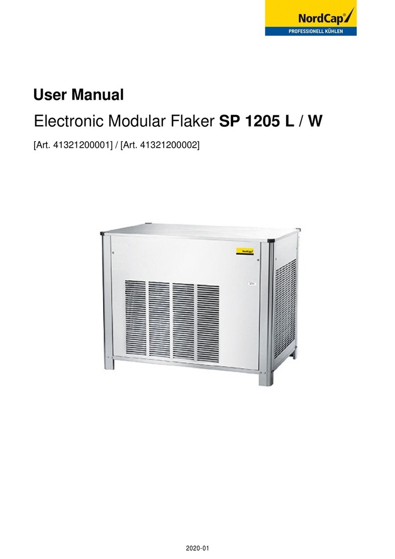
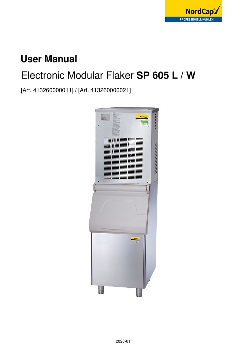
Nordcap SCE 50 W User manual

SERVICE MANUAL
BEDIENUNGSANLEITUNG
SCE 50 L / W
(R-134a)
REV. 07/2019
Art. 413405010610 / 413405010620
Eiswürfelbereiter

Betriebsanleitung
Inbetriebnahme
Nachdem Sie den Eisbereiters korrekt installiert
haben und alle Rohre und elektrischen
Verbindungen verlegt sowie alle Anschlüsse
vorgenommen haben, führen Sie die folgenden
Schritte zur Inbetriebnahme durch.
SCE 20 - 30 - 40 - 50
A. Entfernen Sie die Frontabdeckung der
EinheitundsuchenSiedenReinigungsschalter.
B. Stellen Sie den Reinigungsschalter in die
Position “Reinigen“ (II). Hierdurch wird der
elektrische Stromkreis zum Wassereinlaßventil
und zum Heißgas - Magnetventil gesperrt.
C. Schalten Sie den Stromkabel –
Deaktivierungsschalter ein (ON). Die Einheit
schaltet in die Wasserfüllphase ein. Während
dieser Phase werden folgende Komponenten
aktiviert:
Wassereinlaß – Magentventil
Heißgas – Magnetventil
Die Wasserpumpe und der Ventilatormotor sind
ebenfalls in Betrieb.
D. Lassen Sie die Einheit ungefähr 3 bis 4
Minuten im Abtauzyklus, bis das Wasser aus
dem Abflußschlauch kommt, bringen Sie dann
den Reinigungsschalter wieder in die
Betriebsposition (I).
SCE 65 - 90 - 105
1. Versuchen, das Gerät mit dem
HauptschalterbetreibendasGerätbeginntseine
erste Gefrierphase, bei Betätigung des ON
Schalters.
Folgende Bestandteile sind aktiviert:
Wassereinlassventil
Heissgasventil
Timer Motor
HINWEIS:
Während des Abtauzyklus wird
das Wassereinlaß – Magnetventil aktiviert.
Das Wasser fließt durch das Ventil zur
Oberfläche der Verdampferplatte und dann
abwärts, um die Auffangvorrichtung des
Eisbereiters für den nächsten Gefrierzyklus
zu füllen.
Betriebskontrolle
A. Die Einheit startet jetzt ihren ersten
Gefrierzyklus, hierbei sind die folgenden
Bestandteile in Betrieb:
Kompressor
Wasserpumpe
Ventilatormotor bei der luftgekühlten Version
B. SehenSiedurchdieEisauswurföffnung,um
sicherzustellen, daß das Sprühsystem korrekt
montiertistunddaßdieWasserdüsendasInnere
der Kegelformer gleichzeitig erreichen; stellen
Sie ferner sicher, daß der Kunststoffvorhang frei
hängtunddaßnichtzuvielWasserdurchdiesen
hindurchdringt.
C. DasEisbereitungsverfahrenverläuftso,daß
Wasser in die Former gesprüht wird und dann
allmählich gefriert, wobei die Wärme an das
Kühlmittel abgegeben wird, welches in die
Verdunsterschlange geleitet wird.
D. IndieModelleSCE20-30-40-50,wenndie
Verddampfertemperatur einen vorher
festgelegten Wert erreicht, ändert der
Verdampferthermostat oder die Würfelgrößen-
steuerung die Kontakte; der Gefrierzyklus endet
und der Abtauzyklus beginnt.
BeidenModelleSCE65-90-105drehtsichder
Timer nicht an Ende der Abtauphase. Er startet
später,wenn derVerdampferthermostat-Fühler,
in dem Verdampfer gestellt, die Temperatur von
etwa -15°C (5F) erreicht.
E. DerGefriervorgangdauertzwischen20und
22 Minuten bei einer Umgebungtemperatur von
21°C. Der Vorgang dauert länger, wenn die
Temperatur höher ist, weniger lange, wenn die
Temperatur niedriger ist. Ein durchschnittlich
durchgeführter Zyklus dauert zwischen 23 und
25 Minuten.
F. ÜberprüfenSiewährenddeserstenAbtau-
/ Ausgabezyklus‘, daß das Wasser korrekt in
dieAuffangvorrichtung fließtunddiesekorrekt
aufgefüllt wird. Das überschüssige Wasser
muß in das Überfluß – Ablaufrohr geleitet
werden.
G. Kontrollieren Sie die Beschaffenheit der
frischenEiswürfel. Die korrekte Größe muß eine
kleine Vertiefung (ungefähr 4 - 5 mm) an der
Oberseite aufweisen. Sollte dies nicht der Fall
sein, warten Sie den zweiten Abtau- /
Ausgabezyklus ab, bevor Sie Veränderungen
vornehmen.
H. Sofern notwendig, bei den Modelle
SCE 20 - 30 - 40 - 50 kann die Länge des
Gefrierzyklus durch Drehen des Verdampfer-
thermostat auf der Vorderseite der Schalttafel
2

angepaßt werden, bis die gewünschte Größe
erreicht wird. • Wenn die Raum-
temperatur, wo
sich das Gerät
befindet, unter
20ºC liegt, werden
dieWürfel teilweise
hohl sein (siehe
Abbildungrechts).
• Wenn die Raum-
temperatur, wo
sich das Gerät
befindet,höherals
30ºC liegt, werden
die hergestellten
Würfel einen
dickeren Eisrand
um der "Krone"
herum haben.
Wenn unbedingt notwendig kann die oben-
genannteSituationwiefolgtabgeändertwerden:
indemerstenFallbeiDrehung,imUhrzeigersinn,des
Kontrolknopfes (wenig oder mehr, wie man will)
in dem zweiten Fall bei Drehung, im
Gegenuhrzeigersinn (nach rechts) des
Kontrolknopfes.
Es soll bemerkt werden dass wenn die
Raumtemperatur später wieder auf 20÷30°C
sinkt, bei soll der Knopf wieder auf dem weissen
Punkt gedreht werden (siehe Ab. unten).
Wenn die Eiswürfel flach und trüb sind, ist es
möglich, daß der Eisbereiter gegen Ende des
Gefrierzyklusmit zu wenigWasserversorgtwird
oderdaßdieQualitätdeszufließendenWassers
denEinsatzeinesentsprechendenWasserfilters
oder Conditioners erforderlich macht.
I. Halten Sie während des Ausgabezyklus‘
eine Handvoll Eiswürfel gegen den
Temperaturfühler des Vorratsbehälter-
thermostats. Der Eisbereiter schaltet sich dann
innerhalbvon1bis2Minutenab.EntnehmenSie
dasEisausdemVorratsbehälterthermostat.Der
Eisbereiter nimmt innerhalb von 3 bis 4 Minuten
den Betrieb automatisch wieder auf.
HINWEIS:
DerVorratsbehälterthermostatist
werkseitig eingestellt auf 1
°
C AUS und 4
°
C
EIN.
K. Bringen Sie die Frontabdeckung der
Einheit wieder an und weisen Sie dann den
Eigentümer/BenutzerindenallgemeinenBetrieb
des Eisbereiters ein, und informieren Sie Ihn
ferner über alle erforderlichen Reinigungs- und
Wartungsmaßnahmen.
3

Betrieb
Funktionsweise des Eisbereiters
Im Eisbereiter wird das Wasser, das zur
Eisherstellung benötigt wird, ständig von einer
Wasserpumpe in Bewegung gehalten. Diese
Wasserpumpe pumpt es zur Sprühsystemdüse,
vonwoausesindieKegelformerdesVerdunsters
geleitet wird (siehe Abb. A).
Eine geringe Menge des gesprühten Wassers
friert zu Eis der Rest läuft bedingt durch die
Schwerkraft kaskadenartig zurück in die
Auffangvorrichtungdarunterund kann so erneut
in Umlauf gebracht werden.
Gefrierzyklus (Abb. B)
Das Heißgaskühlmittel, daß vom Kompressor
abgeschieden wird, erreicht den Kondenser, wo
es heruntergekühlt wird und in den flüssigen
Zustand kondensiert.
Es fließt dann in die Flüssigkeitsleitung und
passiertden Trockner /Filter. Von dortaus fließt
esbiszumKapillarröhrchen,woesseinenDruck
verliert.
Daraufhin gelangt das Kühlmittel in die
Verdunsterschlange(dieseweisteinengrößeren
Durchmesser als das Kapillarröhrchen auf) und
beginnt zu kochen. Dieser Vorgang wird noch
unterstützt durch die Wärme die von dem
Sprühwasser übertragen wird.
Das Kühlmittelvolumen erhöht sich, es wird
vollständig zu Dampf.
Der Kühldampf passiert den Saugakkumulator
(dieser wird verwendet, um zu verhindern, daß
kleine Mengen von flüssigem Kühlmittel in den
Kompressor gelangen) und gelangt durch die
Saugleitung.
Sowohl im Akkumulator als auch in der
SaugleitunggibtesdieWärmeandasKühlmittel
ab, welches durch das Kapillarröhrchen fließt
(Wärmer), bevor es in den Kompressor gesaugt
wird und als heiß komprimiertes Kühlmittelgas
wieder in Umlauf gelangt.
Der Gefrierzyklus der SCE 20 - 30 - 40 - 50
Modelle wird vom Verdunster-thermostat
gesteuert dessen Temperaturfühler in
Berührung mit der Verdunsterschlange steht,
während in den SCE 65 - 90 - 105 Modelle
gibtes eine zweite Phase von dem Timer
gesteuert.
DieelektrischenKomponenten,diewährenddes
Gefrierzyklus in Betrieb sind, sind folgende:
Kompressor
Wasserpumpe
Ventilatormotor (bei der luftgekühlten Version)
Bei den luftgekühlten Versionen ist der
Kühlmitteldruck allmählich von ungefähr 11 bar
(155 psig) zu Beginn des Gefrierzyklus mit einer
Einheitbei21°CUmgebungstemperaturaufeinen
Mindestwert von ungefähr 7 bar (100 psig)
während der letzten Sekunden kurz vor Ende
des Gefrierzyklus und bevor der Abtauzyklus
beginnt gesenkt.
Das Sinken des Drucks hängt mit der
Reduzierung des Verdunstungsdrucks
zusammen, der von dem progressiven
Wachstum der Eisstärke in den Kegelformern
unddemvomVentilatorkommendenLuftstroms
durch den luftgekühlten Kondenser verursacht
wird.
DieobenaufgeführtenWertesinddirektabhängig
vonderUmgebungstemperaturdesEisbereiter-
standorts. Die Werte steigen, wenn die
Umgebungstemperatur sich erhöht.
Bei den wassergekühlten Versionen liegt der
Kühlmitteldruck zwischen 8,5 und 10 bar.
Der Druck wird gesteuert durch eine
automatische Hochdrucksteuerung, die ein
Wassereinlaß - Magnetventil an der
Wasserleitung zum Kondenser, durch die das
Kühlwasser zum Kondensor gelangt, betätigt.
BeidenSCE 90 -105 wassergekühlten Modelle
istderHochdruck,vondemWasserregulierventil
kontrolliert.
ZuBeginndesGefrierzyklussinktdieAnsaugung
des Kühlmittels oder der Niedrigdruck schnell
auf 1,0 bar danach fällt der Druck allmählich ab
- in direktem Bezug zur wachsenden Eisstärke -
umschließlichgegenEndedesZyklusungefähr
0 + 0,1 bar wenn die Eiswürfel im Kegelformer
vollkommen ausgeformt sind.
Die Gesamtlänge des Gefrierzyklus liegt
zwischen 23 und 25 Minuten.
Abtau- oder Ausgabezyklus (Abb. D)
Bei den SCE 20 - 30 - 40 - 50 Modelle, wenn die
Temperatur des Verdampfer-thermostats, der
sich in Berührung mit der Verdunsterschlange
befindet, auf einen vorher eingestellten Wert
fällt, ändern sich hierdurch die elektrischen
Kontakte,sodaßfolgendeKomponentenaktiviert
werden (Bei den SCE 65 - 90 - 105 Modelle,
wennderMikroschalterdesTimersinderunteren
Seite des Nockens fällt, ändert dieser seine
elektrische Kontakte und aktiviert die selben
Bestandteilen):
Kompressor
Wassereinlaß – Magnetventil
Heißgas – Magnetventil
Das zufließende Wasser fließt zunächst durch
das Wassereinlaß - Magnetventil und die
Flußsteuerung, läuft über die Verdunsterplatte
und wird dann von der Schwerkraft durch die
Tropflöcher in die Auffangvorrichtung / den
Behälter (Abb. C) gelenkt.
4

DurchdasWasser,dasindieAuffangvorrichtung
/ den Behälter gelangt, wird das überschüssige
Wasser des vorherigen Gefrierzyklus verdrängt
und fließt in das Überflußrohr. Dieser Überfluß
begrenzt das Niveau der Wasserauffang-
vorrichtung.DasaufgefangeneWasserwirddazu
verwendet, um den nächsten Satz Eiswürfel zu
produzieren.
DasKühlmittelwirdalsHeißgasvomKompressor
abgeschiedenundgelangtdurchdasHeißgas–
Magnetventil direkt in die am Kondensor vorbei
führende Verdunsterschlange.
Der Heißgasumlauf in die Verdunsterschlange
erwärmtdie Kupferformen, sodaß die Eiswürfel
ausgeworfenwerden.DieausdenKegelformern
ausgeworfenen Eiswürfel fallen durch die
Schwerkraft auf eine geneigte Würfelrutsche,
gelangen durch die Öffnung mit dem Vorhang
undfallenindenEiswürfel–Vorratsbehälter.Bei
den SCE 20 - 30 - 40 - 50 Modelle wenn die
Temperatur des Temperaturfühlers des
Verdunstertermostats eine Höhe von +3 ±4°C
erreicht, werden dessen elektrische Kontakte
zurückaufdievorherigePositionbewegtundein
neuer Gefrierzyklus wird aktiviert. Sowohl das
Heißgas - als auch das Wassereinlaß -
Magnetventil werden deaktiviert (geschlossen).
Bei den SCE 65 - 90 - 105 Modelle, wenn der
Mikroschalter des Timers die untere Seite des
Nockens beendet ist und wieder betätigt
wird,
eine neue Gefrierphase beginnt (Heisgassventil und
Magnetventil werden deaktiviert - geschlossen).
HINWEIS:
Bei den SCE 20 - 30 - 40 - 50
Modelle die Länge des Abtau- /
Auswerfzyklus‘istabhängig(nichteinstellbar)
von der Umgebungstemperatur (kürzer bei
hoherUmgebungstemperaturundlängerbei
niedriger Umgebungstemperatur).
Beschreibung der Komponenten
A. Wasserpumpe
DieWasserpumpearbeitetkontinuierlichwährend
desGefrierzyklus‘.DiePumppumptdasWasser
ausderAuffangvorrichtungindasSprühsystem.
Durch die Sprühdüsen wird das Wasser in die
Kegelformer gesprüht, wo es zu kristallklaren
Eiswürfeln gefriert.
B. Wassereinlaß - Magnetventil - 3/4"
Steckverbindungsstück
Das Wassereinlaß - Magnetventil wird nur
während des Abtauzyklus aktiviert.
Wenn es aktiviert ist, läßt es eine bestimmte
Menge zufließenden Wassers über die
Verdunstervertiefung fließen, um somit
zusammen mit dem Heißgas für das Abtauen
des Eises zu sorgen. Das Wasser, daß über die
Verdunstervertiefung läuft, tropft, bedingt durch
dieSchwerkraft,durchdieTropflöcherderPlatte
in die Auffangvorrichtung.
Bei den SCE 20 - 30 - 40 - 50 - 65
wassergekühlten Versionen ist das
Wassereinlaß-Magnetventilmit einem Einlaß
und zwei Auslässen mit zwei voneinander
getrenntenTopfmagnetenausgestattet,wobei
der erste (für die Eisproduktion) durch die
Kontakte 3 – 2 des Verdunsterthermostats
aktiviert wird und der zweite (wassergekühlter
Kondenser) durch eine spezielle Hochdruck-
steuerung.
C. Heißgas – Magnetventil
Das Heißgas – Magnetventil besteht
hauptsächlichauszweiTeilen:DemVentilkörper
undderVentilspule.DasHeißgas-Magnetventil
befindet sich and der Heißgasleitung und wird
von den Kontakten 3 – 2 des Verdunster-
thermostats während des Abtauzyklus aktiviert.
Während des Abtauzyklus wird das die Heißgas
–Ventilspuleaktiviert,undziehtsomitdenKolben
desHeißgas–Magnetventilsan.Hierdurchkann
dasHeißgas,dasvomKompressorabgeschieden
wird,direktindieVerdunsterschlangegelangen,
um dort die geformten Eiswürfel durch Antauen
zu lösen.
D. Vorratsbehälterthermostat
Das Steuerteil des Vorratsbehälterthermostats
befindet sich vorne auf der Schalttafel hinter der
abnehmbaren Abdeckung.
Das Fühlrohr des Thermostats befindet sich in
einem Temperaturfühlhalter an der Seitenwand
des Eisauffangbehälters, wo es den Eisbereiter
automatisch abschaltet, wenn der Fühler in
BerührungmitdemEiskommtunddenEisbereiter
automatisch wieder aktiviert, wenn das Eis
entferntwird.DiewerkseitigenEinstellungensind
1°C AUSSCHALTEN und 4°C EINSCHALTEN.
E. Würfelgrößensteuerung
(Verdampferthermostat)
SCE 20 - 30 - 40 - 50
Die Würfelgrößensteuerung (Verdampfer-
thermostat) sitzt vorne auf der Schalttafel hinter
der abnehmbaren Abdeckung. Sie ist
hauptsächlich
eine umgekehrt fungierende
Temperatur-steuerung, die die Kontakte 3 – 2
schließt, wenn die Temperatur fällt und die
gegenüberliegenden
Kontakte3–4schließt,wenn
die Temperatur steigt.
Der Temperaturfühler befindet sich in einem
Kunststoffrohr (Fühlerhalter), der von zwei
Klemmen direkt an der Verdunsterschlange
befestigtist.DieseSteuerungbestimmtdieLänge
desGefrierzyklusunddemzufolgeauchdieGröße
der Eiswürfel.
EineniedrigereEinstellungresultiertingrößeren
Eiswürfeln (Übergröße) während eine höhere
Einstellung geringere Eiswürfeln (flache Würfel)
zur Folge hat. Wenn die Kontakte 3 – 2
geschlossensind,aktiviertsiedieKomponenten
des Abtau- oder Auswerfzyklus‘.
Die Würfelgrößensteuerung wird werkseitig
eingestellt (Knopf in der Position mit dem
schwarzenPunkt)undmußnichtweitereingestellt
werden, sofern die Temperaturanforderungen
zwischen 20 und 30°C eingehalten werden (70
und 90°F)
SCE 65 - 90 - 105
Der Verdampferthermostat mit seinem
empfindlichenFühlerinKontaktmitdemAussen
rohr des Verdampfers "liest" die Kühlmittel-
Verdampfungstemperatur (die während der
Gefrierphase sinkt) und wenn diese den
5

M. Platine (nur SCE 65 - 90 - 105)
Die Platine hat zwei DIP-Schalter und ein
Potentiometer für die Einstellung der zweiten
Gefrierphase und der Abtauphase.
DieseZeitensindWerksseitigbereitseingestellt.
DerersteSchalter(KompressorSchalter),ersetzt
die frühere elektomechanische version,
Werkseinstellung AN um im Normalbetrieb den
Kompressor mit Spannung zu versorgen. Steht
derSchalteraufAUS,läuftnurdieWasserpumpe.
ErforderlichfürdieReinigung.DerzweiteSchalter
ist für die Zeiteinstellung Ta des Gefrierzyklus
bezugnehmendaufdasModellderEismaschine
Werkseinstellung der DIP-Schalter
N. 1 N. 2
SCE 65 EIN EIN
SCE 90 EIN EIN
SCE 105 EIN EIN
Funktionen Schalter 1 & 2
N. 1 N. 2
ON Standard
Kompressor AN
Reinigung
OFF Kompressor
AUS
Das Potentiometer wird verwendet um die
Abtauzeit einzustellen und ist Werksseitig auf
das jeweilige Model bereits eingestellt. Die
Abtauzeit kann eingestellt werden von 60“ bis
180“ im Uhrzeigersinn.
N.
Lüfter-Pressostat (nur SCE 65 - 90 - 105)
Verwendet auf Luftgekühlte Modelle, hält den
HochdruckzwischendervorherbestimntenWerte
ein.
O. Wasserregulierventil
(nur
SCE 65 - 90 - 105
wassergekühlt)
Dieses Ventil steuert den Hochdruck im
Kältemittelkreislauf, bei Regulierung der
Wassermenge zu dem Kondensator. Wenn der
Druck steigert, öffnet sich das Ventil um den
Wasserstrom zu erhöhen.
P. Fernschalter (nur
SCE 65 - 90 - 105
)
Schliesst oder öffnet den elektrischen Kreis zu
dem Kompressor.
vorherbestimmtenWerterreicht,schalteterseine
Kontakte von 3-4 an 3-2, um die Endphase (2e
Phase) zu aktivieren. Diese 2e Phase hat eine
vorherbestimmteDauer,durchdieDiameterbreite
der Kreislinie des Timernockens bestimmt ist.
F. Ventilatormotor (luftgekühlte Version)
ModelleSCE20-30-40-50derVentilatormotor
ist elektrisch mit der Wasserpumpe
parallelgeschaltet und arbeitet kontinuierlich
während des Gefrierzyklus‘, um den richtigen
Druck durch die Luftzirkulation durch die
Kondenserrippen zu gewährleisten.
Bei SCE 65 - 90 - 105 der Betrieb des
Ventilatormotors ist durch ein Pressostat, an
vorherbestimmtenWerteeingestellt,kontrolliert.
G. Kompressor
Der hermetisch versiegelte Kompressor ist das
Kernstück des Kühlmittelsystems. Er wird
verwendet, um das Kühlmittel im gesamten
System umlaufen zu lassen und zum Schluß
wieder aufzufangen. Er komprimiert den
Niedrigdruck – Kühldampf, läßt dessen
Temperatur somit steigen und wandelt den
Niedrigdruck – Kühldampf in Hochdruck –
Heißdampf (Heißgas), welcher durch das
Abgabeventil abgelassen wird.
H. Wassersprühsystem
DurchdieDüsendiesesSystemswirddasWasser
in jede einzelne Kegelform gesprüht, wo es zu
Eis gefriert.
I . Hochtemperatur–Sicherheitsthermostat
Der Thermostat befindet sich unten an der
Schalttafel.EristeinmanuellerRückstellschalter,
der auslöst und den Betrieb der Eismaschine
unterbricht,wennderTemperaturfühler(dersich
an der Leitung vor dem Trockner befindet), eine
Temperatur von 70°C erreicht.
J. Reinigungsschalter
(nur SCE 20 - 30 - 40 - 50)
Er befindet sich unten links an der Schalttafel
undwirdverwendet,umdasWassereinlaß–und
dasHeißgas–Magnetventilzubetätigen,sodaß
das Wasser in die Auffangvorrichtung der
Maschine gelangen kann.
K. Hochdrucksteuerung
(SCE 20 - 30 - 40 - 50 - 65
Wassergekühlte Version)
Diese Steuerung wird nur in wassergekühlten
Versionen verwendet. Bei zwischen 8,5 und 10
bar sorgt sie dafür, daß der Druck des
Kühlmittelsystems gehalten oder gesenkt wird,
indem sie die Spule des Wassereinlaß –
Magnetventils, das wiederum den Fluß des
Kühlwassers zum Kondenser steuert, aktiviert.
L. Hauptschalter
(nur SCE 65 - 90 - 105)
Befindet sich in dem Schaltkasten, schaltet das
Gerät ein-aus.
Ta = 12'
Ta = 8'
P
R
O
.
E
L
.I
N
D
RELAIS
WASSEREINLASS
UND
HEIßGASVENTIL
WERKNUTZUNG
RELAIS
WASSERPUMPE
RELAIS
KOMPRESSOR
TERMINAL
BOARD
TRANSFORMATOR
TERMINAL
BOARD
KOMPRESSOR AUS/AN
ZEITSCHALTER 8/12’
EINSTELL
ABTAUUNG
TEST JUMPER
6

Anweisungen zur Wartung
und Reinigung
AnweisungenzurReinigungdesWassersystems
1. Entfernen Sie die vordere und obere
Abdeckung,umZugangzurSchalttafel und zum
Verdampfer ermöglichen.
2. Stellen Sie sicher, daß alle Eiswürfel aus
IhrenKegelformengelöstwordensind.DasGerät
durch den Hauptschalter.
3. Entfernen Sie alle Eiswürfel, die sich noch
im Vorratsbehälter befinden, damit sie nicht mit
der Reinigungslösung kontaminiert werden.
4. Das Kunstoffteil in der unteren Seite des
Gefriergehäuses beseitigen um den das ganze
Wasser und Kalkablagerung zu entfernen.
5. Die Jalousie beseitigen, und mit einer
FlaschefrischesWasserinderunterenSeitedes
Gefriergehäuses spühlen.
6. Die Jalousie sowie das Kunstoffteil wieder
einsetzen.
7. Für alle Modelle, das Wasser von dem
Behälter/Reservoir, durch die Entfernung des
Ueberlaufschlauch, rausfliessen lassen.
8. Bereiten Sie eine Reinigungslösung vor,
indemSie einen oder zwei Liter warmes Wasser
(45°- 50°C) mit 0,2 Liter Eismaschinen-reiniger
verdünnen.
WARNUNG: Der Eismaschinenreiniger
enthält Phosphor und Hydroxysäure.
DieseBestandteilesindkorrodierendund
können Verbrennungen verursachen,
wenn Sie geschluckt werden. Sollte dies
derFallsein,forcieren Sienichtkünstlich
ein Übergeben. Geben Sie große Mengen
Wasser oder Milch zu trinken. Rufen Sie
sofort einen Arzt.
Bei einem Hautkontakt spülen Sie die
entsprechende Stelle mit Wasser ab.
HALTEN SIE DAS REINIGUNGSMITTEL
AUSSER REICHWEITE VON KINDERN!
9. Entfernen Sie die Abdeckung des
Verdunsters und gießen Sie dann die
Reinigungslösung langsam über die
Verdunsterplatte. Lösen Sie die hartnäckigsten
Schmutz-und Kalkablagerungen von der Platte.
SCE 20 - 30 - 40 - 50
1. DasGerätwiederdurchdemHauptschalter
einschalten um die Eisproduktion beginnen zu
lassen.
LassenSie denEisbereiterungefähr20Minuten
lang arbeiten. Drehen Sie dann den
Reinigungs-
schalterindiePosition"Reinigen",bisdieEiswürfel
aus ihren Kegelformen gelöst sind (II).
HINWEIS:
Die Menge an Reinigungsmittel
und die Zeit, die für die Reinigung des
Wassersystems benötigt wird, hängt vom
Wasserzustand ab.
2. Drehen Sie den Würfelgrößen -
Steuerungsknopf entgegen dem Uhrzeigersinn
in die Position OFF (AUS), um den Eisbereiter
auszuschalten. Spülen Sie dann die
Reinigungslösung aus der Auffangvorrichtung.
Danach gießen Sie zwei bis drei Liter reinen
Trinkwassers in die Verdunstervertiefung, um
die Kegelformen und die Platte abzuspülen.
3. Gegebenenfalls entfernen Sie die
Wassersprühplatte und reinigen diese separat.
4. DrehenSiedenWürfelgrößen–Steuerungs-
knopf wieder in die normale Betriebsposition
(schwarzer Punkt). Die Wasserpumpe nimmt
den Betrieb auf und läßt Wasser umlaufen, um
das gesamte Wassersystem zu reinigen.
Führen Sie die Schritte 8 und 9 zweimal aus, um
sicherzustellen,daßkeineSpurenvonEntkalker-
bzw. Reinigungslösung mehr in der
Auffangvorrichtung vorhanden sind.
Gießen Sie frisches Wasser unter Zugabe einer
Kappe Desinfizierungslösung auf die Oberseite
der Verdunsterplatte. Bringen Sie die Maschine
erneut in normalen Betrieb, um das ganze
Wassersystem ungefähr 10 Minuten lang zu
desinfizieren.
HINWEIS:
MischenSiedieReinigungs-bzw.
EntkalkungslösungnichtmitderDesinfektion-
slösung,eskönnte sich ansonsteneine sehr
aggressive Säure bilden.
5. Spülen Sie die Desinfizierungslösung aus
der Auffangvorrichtung. Stellen Sie sicher, daß
sich der Reinigungsschalter in der Position
Reinigung“ befindet und drehen sie den
Würfelgrößen–Steuerungsknopfin die normale
Betriebsposition.
Wenn das Wasser anfängt, durch die
Abflußleitung zu fließen, setzen Sie den
Reinigungsschalter wieder zurück in die
Betriebsstellung. Die Einheit ist jetzt bereit für
den normalen Betrieb.
7

SCE 65 - 90 - 105
1. Schalten Sie das Gerät am Hauptschalter
undverschiebenSiedanndenerstenDipSwitch
Schalter in die Position OFF.
Auf diese Weise wird der Kompressor nicht
angetriebenwarden, und die einzige Komponente
inBetriebwährendderWaschphasewirdwarden
Wasserpumpe sein.
2. Lassen Sie das Gerät etwa 20 Minuten in
der Gefrierphase arbeiten. Kein Eis wird
produziertdaderKompressornichtinBetriebist.
3. An Ende dieser Zeit den Hauptschalter auf
OFF stellen, um das Gerät auszuschalten.
4. DerÜberlauf-ablaufSchlauchentfernenum
dieReinigungslösungunddieMineralrestedurch
denAblaufrohrrausfliessenzulassen;dannden
Überlaufschlauch wieder einsetzen.
5. Giessen Sie 2-3 Liter frisches Wasser auf
den Verdampfer um die Platte zu spülen.
6. Wennnötig die Wassersprühplatte separat
entfernen und reinigen.
7. Stellen Sie wieder den Hauptschalter auf
ON. Die Wasserpumpe ist wieder aktiviert und
somit das Wasser den kompletten
Wasserkreislauf spült.
8. GiessenSiefrischesWasserunterZugabe
einerkappeDesinfizierungslösungaufdieobere
Seite der Verdampfungsplatte und das Gerät
erneut in Betrieb setzen um das ganze
Wassersystem etwa 10 Minuten lang
desinfizieren.
HINWEIS:
MischensiedieReinigungs-bzw.
Entkalkungslösung nicht mit der
Desinfektionslösung,eskönntesichansosten
eine seht agressive Säure bilden.
9. Schalten Sie das Gerät und laden Sie die
Desinfektionslösung aus dem Tank.
10. Stellen Sie den Netxschalter auf ON.
11. Hassen Sie die Maschine ein komplettes
Abtauen um den Wassertank zu füllen.
12. Wenn das Abgas aus dem Wasser Start
des Verdichters Inbetriebnahme des ersten Dip
Switch Schalter auf ON, um so in Betrieb das
Gerät anrufen, um.
13. Diee Maschinen, und nun bereit für den
automatischen Betrieb und kontinuierliche.
14. Montieren Sie die Verdunsterabdeckung
und die Wartungsabdeckungen der Einheit.
15.
NachdemderGefrier-undderAuswerfzyklus
abgeschlossen sind, stellen Sie sicher, daß die
EiswürfeldierichtigeKonsistenzundTransparenz
aufweisenunddaßsiekeinesaurenGeschmack
haben.
ACHTUNG: Wenn die Eiswürfel trüb sind
und einen sauren Geschmack haben,
schmelzenSiesofort durchBegießen mit
warmem Wasser. Dies verhindert, daß
diese Eiswürfel von jemandem anders
verwendet werden.
16. Wischen Sie die Innenflächen des
Vorratsbehälters sauber und spülen Sie sie
nochmals ab.
ERINNERUNG:
Um die Sammlung von
unerwünschten Bakterien zu verhindern ist
es notwendig, das Innere des Vorrats-
behälterseinmalproWochemiteinemAnti–
Algen–Desinfizierungsmittelauszuwischen.
8

OPERATING INSTRUCTIONS
START UP
After having correctly installed the ice maker and
completed the plumbing and electrical
connections, perform the following “Start-up”
procedure.
SCE 20-30-40-50
A. Remove the unit front panel and locate the
cleaning switch on the control box.
B. Set the cleaning switch in the cleaning
position (II). This will close the electrical circuit to
the water inlet valve and to the hot gas valve.
C. Switch ON the power line disconnect switch.
Unit will start up in water filling phase mode.
During this phase the components energized
are:
WATER INLET SOLENOID VALVE
HOT GAS SOLENOID VALVE
The Water pump and the Fan motor are also in
operation.
D. Let unit stay in water filling phase mode for
about three/four minutes till water is coming out
from the drain hose, then move the cleaning
switch to the operation position (I).
SCE 65-90-105
A. Give power to the unit to start it up by
switching ON the power line main switch; the unit
will start automatically in defrost cycle with the
following components energized:
WATER INLET SOLENOID VALVE
HOT GAS VALVE
COMPRESSOR
ELECTRONIC TIMER
NOTE.
During the defrost cycle, the water
inlet solenoid valve is energized. The water
flows through the valve to the back side of the
evaporator platen and then down to fill up the
icemaker sump tank for the next freezing cycle.
OPERATIONAL CHECKS
A. The unit now starts its first freezing cycle
with the following components in operation:
COMPRESSOR
WATER PUMP
FAN MOTOR in air cooled version
B. Check to see through the ice discharge
opening that the spray system is correctly seated
and that the water jets uniformely reach the
interior of the inverted cup molds; also make sure
that the plastic curtain is hanging freely and there
is not excessive water spilling through it.
C. The ice making process takes place thereby,
with the water sprayed into the molds that gets
gradually refrigerated by the heat exchanged
with the refrigerant flowing into the evaporator
serpentine.
D. On units SCE 20 -30 - 40 . 50 when the
evaporator temperature reaches a preset value
the evaporator thermostat or cube size control
changes its contacts; the freezing cycle ends and
starts the defrost or harvest cycle.
E. On models SCE 65 - 90 - 105 freezing cycle
is completed through an electronic timer
energized by the evaporator thermostat. It starts
when the cube size thermostat/control bulb (pig
tail) located on the evaporator serpentine reaches
a temperature of approx. -15°C (5°F)
.
On units SCE 65 - 90 - 105 the additional
Time (12') of the freezing cycle starts when
the cube size thermostat control bulb (pig
tail) located on the evaporator coil reaches a
temperature of approx. -15
°
C. Freezing time
will range between 20 and 22 minutes in a
21
°
C ambient temperature, longer if above
this temperature and shorter if below.Then
the unit goes directly into the Defrost Cycle.
The average complete cycle time is between
23 and 25 minutes.
F. Check, during the first defrost/harvest cycle,
that the incoming water flows correctly into the
sump reservoir in order to re-fill it and the
surplus
overflows through the overflow drain tube.
G. Check the texture of ice cubes just released.
Right size must have a small depression (about
5-6 mm) in their crown.
If not, wait for the second defrost/harvest cycle
before performing any adjustment.
H.
If required on model SCE 20 - 30 - 40 - 50
, the
length of the freezing cycle can be modified by
turning the knob of the cube size control or
evaporator thermostat located
in front of the machine
until the desired size is achieved.
9

If it is thought necessary, the above situations
can be rectified by, in the first case, turning the
control knob (as little or as much as is required)
clockwise and, in the second case, turning the
knob to the right counterclockwise.
It should, however, be remembered that if the
room temperature returns later to the 20 ÷ 30°C
range, the knob indicator must once again be
turned to the previous position.
If the ice cubes are shallow and cloudy, it is
possible that the ice maker runs short of water
during the end of the freezing cycle or, the quality
of the supplied water requires the use of an
appropriate water filter or conditioner.
I. At the end of the defrost or harvest cycle
hold a handful of ice cubes against the bulb of the
storage bin thermostat; the icemaker switch OFF
in about one-two minutes.
Take out the ice from the storage bin thermostat.
The ice maker should restart automatically in
three-four minutes.
NOTE.
The bin thermostat is factory set at
1
°
C (35
°
F) OUT and 4
°
C (39
°
F) IN.
K. Re-fit the unit front panel then instruct the
owner/user on the general operation of the ice
machine and about the cleaning and care it
requires.
• If the tempera-
ture of the room in
which the machine
is place is below
20°C, the cubes
will tend to be
partly hollowed
out (see fig. on
right).
• If, on the other
hand, the room
temperature is
above 30 °C the
cubes produced
will have a jagged
rim of ice around
the crown.
10

PRINCIPLE OF OPERATION
How it works
In the ice makers the water used to make the ice
is kept constantly in circulation by a water pump
which primes it to the spray system nozzles from
where it is diverted into the inverted cup molds of
the evaporator (Fig. A).
A small quantity of the sprayed water freezes into
ice; the rest of it cascades by gravity into the
sump assembly below for recirculation.
FREEZING CYCLE (Fig. B)
The hot gas refrigerant discharged out from the
compressor reaches the condenser where, being
cooled down, condenses into liquid. Flowing into
the liquid line it passes through the drier/filter,
then it goes all the way through the capillary tube
where it looses its pressure.
Next the refrigerant enters into the evaporator
serpentine (which has a larger diameter then the
capillary tube) and starts to boil off; this reaction
is emphasized by the heat transferred by the
sprayed water.
The refrigerant then increases in volume and
changes entirely into vapor.
The vapor refrigerant then passes through the
suction accumulator (used to prevent that any
small amount of liquid refrigerant may reach the
compressor) and through the suction line. In both
the accumulator and the suction line it exchanges
heat with the refrigerant flowing into the capillary
tube (warmer), before to be sucked in the
compressor and to be recirculated as hot
compressed refrigerant gas.
The freezing cycle on SCE 20 - 30 - 40 - 50 is
controlled by only the evaporator thermostat
which has its bulb in contact with the evaporator
serpentine while in SCE 65 - 90 - 105 there is
an second phase controlled by an electronic
timer.
The electrical components in operation during
the freezing cycle are:
COMPRESSOR
WATER PUMP
FAN MOTOR (in air cooled version)
On air cooled versions the refrigerant head
pressure is gradually reduced from the value of
approx. 11 bar at beginning of the freezing cycle
with the machine at 21°C ambient temperature,
to a minimum value of approx. 7 bar just at the
end of the freezing cycle, few seconds before the
starting of the defrost cycle.
The declining of the pressure is relied to the
reduction of the evaporating pressure, caused
by the progressive growth of the ice thickness
into the inverted cup molds and to the flow of air
drown through the air cooled condenser by the
fan motor.
The above values are in relation as well to the
ambient temperature of the ice maker site and
they are subject to rise with the increase of this
temperature.
On water cooled versions the refrigerant head
pressure ranges between 8,5 and 10 bar being
controlled by an automatic hi pressure control
that energizes a water solenoid valve located on
the water line to the condenser, which rates the
cooling water to the condenser.
On SCE 90 - 105 water cooled version operating,
the head pressure is constant controlled by a
water regulating valve.
At starting of the freezing cycle the refrigerant
suction or lo-pressure lowers rapidly to 1,0 bar
then it declines gradually – in relation with the
growing of the ice thickness – to reach, at the end
of the cycle, approx. 0-0,1 bar with the cubes fully
formed in the cup molds.
DEFROST OR HARVEST CYCLE (Fig. D)
On SCE 20 - 30 - 40 - 50 the temperature of the
evaporator thermostat, in contact with the
evaporator serpentine, drops to a pre-set value
it changes its electrical contacts energizing
the herebelow shown components.
(On SCE 65 - 90 - 105 when the electro-nic timer
completes the second portion of the freezing it
changes its electrical contacts energizing the
same components).
COMPRESSOR
WATER INLET SOLENOID VALVE
HOT GAS SOLENOID VALVE
The incoming water, passing through the water
inlet valve and the flow control, runs over the
evaporator platen and then flows by gravity
through the dribbler holes down into the sump/
reservoir (Fig. C).
The water filling the sump/reservoir forces part of
the surplus water from the previous freezing
cycle to go out to the waste through the overflow
pipe. This overflow limits the level of the sump
water which will be used to produce the next
batch of ice cubes.
Meanwhile the refrigerant, as hot gas discharged
from the compressor, flows through the hot gas
valve directly into the evaporator serpentine by-
passing the condenser.
11

The hot gas circulating into the serpentine of the
evaporator warms up the copper molds causing
the harvest of the ice cubes. The ice cubes,
released from the cups, drop by gravity onto a
slanted cube chute, then through a curtained
opening they fall into the storage bin.
On SCE 20 - 30 - 40 - 50 when the temperature
of the evaporator thermostat bulb reaches the
value of +3 ÷4°C their electrical contacts move
back to the previous position activating a new
freezing cycle and deenergizing both the hot gas
and the water inlet valves (closed).
On SCE 65 - 90 - 105 as soon as the electronic
timer completes the defrost cycle, it activates a
new freezing cycle deenergizing both the hot gas
and the water inlet valves (closed).
NOTE. On models SCE 20 - 30 - 40 - 50 the
length of the defrost/harvest cycle (not
adjustable) changes according to the
ambient temperature (shorter for hi ambient
temperature and longer for low one).
COMPONENTS DESCRIPTION
A. WATER PUMP
The water pump operates continually throughout
the freezing cycle. The pump primes the water
from the sump to the spray system and through
the spray nozzles sprays it into the inverted cup
molds to be frozen into crystal clear ice cubes.
B. WATER INLET SOLENOID VALVE -
3/4 MALE FITTING
The water inlet solenoid valve is energized only
during the defrost cycle.
When energized it allows a metered amount of
incoming water to flow over the evaporator cavity
to assist the hot gas in defrosting the ice cubes.
The water running over the evaporator cavity
drops by gravity, through the dribbler holes of the
platen, into the sump reservoir.
On SCE 20 - 30 - 40 - 50 water cooled versions
the water inlet solenoid valve has one inlet and
two outlets with two separate solenoids energized
the first (ice productioon) by the contacts 3-2 of
the evaporator thermostat and the second (water
cooled condenser) by a specific hi pressure
control.
C. HOT GAS SOLENOID VALVE
The hot gas solenoid valve consists basically in
two parts: the valve body and the valve coil.
During the defrost cycle the hot gas valve coil is
activated so to attract the hot gas valve piston in
order to give way to the hot gas discharged from
compressor to flow directly into the evaporator
serpentine to defrost the formed ice cubes.
D. BIN THERMOSTAT
The bin thermostat control body is located in the
front of control box behind the front panel.
The thermostat sensing tube is located into a
bulb holder on the side wall of the ice storage bin
where it automatically shuts the icemaker OFF
when in contact with the ice and re-starts the
icemaker when the ice is removed. Factory
settings are 1°C (35°F) OUT and 4°C (39°F) IN.
E. CUBE SIZE CONTROL (EVAPORATOR
THERMOSTAT)
SCE 20 - 30 - 40 - 50
The cube size control (evaporator thermostat)
body is located in the control box behind the front
panel; it’s basically a reverse acting temperature
control which closes the contacts 3-2 when its
temperature decreases and closes the opposite
contacts 3-4 when the temperature rises.
The thermostat sensing bulb is located into a
plastic tube (bulb holder) secured by two clips
directly to the evaporator serpentine.
This control determines the length of the freezing
cycle and correspondingly the size of the cubes.
A lower setting will produce a larger cube
(oversize) while a higher setting a smaller cuber
(shallow size).
When closed on contacts 3-2 it activates the
defrost or harvest cycle components.
The cube size control is set up in the factory
(knob in the black dot position) and doesn't
require any adjustment when the ambient
temperature remains between 20 and 30 °C
(70 and 90°F).
SCE 65 - 90 - 105
The evaporator thermostat with its sensing bulb
intimately in contact with the regrigerant outlet
tube from the evaporator senses the evaporating
refrigerant temperature (which declines in the
course of the freezing cycle) and when this one
reaches the pre-set value, it switches its contacts
from 3-4 to 3-2 to activate the finishing cycle (2nd
phase) through an electronic timer.
F. FAN MOTOR (Air cooled version)
The fan motor on SCE 20 - 30 - 40 - 50 is
electrically connected in parallel to the water
pump and it operates continuously only during
the freezing cycle keeping the proper head
pressure by circulating air through the condenser
fins.
On SCE 65 - 90 - 105 the operation of fan motor
is controlled by a fan pressure control adjusted at
preset values.
G. COMPRESSOR
The hermetic compressor is the heart of the
refrigerant system and it is used to circulate and
retrieve the refrigerant throughout the entire
system. It compresses the low pressure
refrigerant vapor causing its temperature to rise
and become high pressure hot vapor (hot gas)
which is then released through the discharge
valve.
H. WATER SPRAY SYSTEM
Through its nozzles it sprays the water in each
individual cup to be frozen into ice.
12

I.
SAFETY HI TEMPERATURE THERMOSTAT
Located in the control box it is a manual reset
switch that trips OFF the operation of the machine
when its bulb (located on the liquid line just
before the drier) reaches the temperature of
70°C (158°F).
J. CLEANING SWITCH
(only SCE 20 - 30 - 40 - 50)
Located on the bottom left side of the control box
is used to energize the water inlet and the hot gas
valves so to charge the water into the sump tank
of the machine.
K. HI PRESSURE CONTROL (Water cooled
version)
Used only on SCE 20 - 30 - 40 - 50 - 65 water
cooled versions it operates to keep between
two preset values the hi-side or discharge
pressure of the refrigerant system by energizing
the coil of the water inlet solenoid valve that
control the cooling water flow to the
condenser.
L. ELECTRONIC TIMER
(SCE 65 - 90 - 105)
Equipped with a Two Keys Dip Switch and one
Potentiometer, it manage the length of second
fase of the freezing cycle and the entire defrost/
harvest cycle with a factory pre-set times .
The first key (1) replaces the “Compressor Switch”
used on the previous electro-mechanical version;
factory setting is ON position to energize the
compressor during the standard operation of the
ice machine.
The same key (1) is switched to OFF position
when the cleaning cycle is required keeping the
water pump only in operation.
The second key (2) allows the setting of the timed
portion (Ta) of the freezing cycle according to the
model of the ice machine.
Dip Switch factory setting combinations
N. 1 N. 2
SCE 65 ON ON
SCE 90 ON ON
SCE 105 ON ON
Resuming Chart with Keys 1 & 2 functions
N. 1 N. 2
ON Standard Setting
Compressor ON
OFF Cleaning Mode
Compressor OFF
The potentiometer is used to adjust the defrost
time and it is set directly from the factory according
to the model of the ice machine.
It can be adjustable from a minimum defrost time
of 60" (turn clockwise), to a maximum of 180"
(turn counterclockwise).
M. MASTER SWITCH
(only SCE 65 - 90 - 105)
Fitted in the control box the master switch has to
be used to start-up and to stop the ice maker
operation.
N. COMPRESSOR SWITCH
(only SCE 65 - 90 - 105)
Located in the control box is used to de-energized
the compressor during the cleaning.
O. FAN PRESSURE CONTROL
(only SCE 65 - 90 - 105)
Used on air cooled ice makers to maintain the
head pressure within the preset values.
P. WATER REGULATING VALVE
(only SCE 90 - 105 Water cooled
version only)
This valve controls the head pressure in the
refrigerant system by regulating the flow of water
going to the condenser.
As pressure increases, the water regulating val-
ve opens to increase the flow of cooling water.
Ta = 12'
Ta = 8'
13

MAINTENANCE AND CLEANING INSTRUCTIONS
CLEANING INSTRUCTIONS OF WATER
SYSTEM
1. Remove the front and top panels to gain
access either to the control box and to the
evaporator.
2. Make sure that all ice cubes have been
released from their cups, then switch OFF the
machine at main power switch, on models SCE
20 - 30 - 40 - 50, and on master switch on models
SCE 65 - 90 - 105.
3. Scoop out all the ice cubes stored into the
bin in order to prevent them from being
contaminated with the cleaning solution.
4. Remove the plastic cup located on the
bottom of sump/freezing chamber to drain out all
water and scale deposits.
5. Remove the curtain then, using a bottle,
poor fresh water into the bottom of the sump/
freezing chamber to clean out any possible scale
deposit.
6. Install again the curtain as well as the
bottom plastic cup.
7. Prepare the cleaning solution by diluting in
a plastic container one or two liters of warm water
(45°-50°C) with a 0,1-0,2 liters of Ice Machine
Cleaner (on SCE 20 - 30 - 40 - 50 - 65
) and 0,2-0,3
liters on SCE 90 - 105.
WARNING. The Ice Machine Cleaner
contains Phosphoric and Hydroxyacetic
acids.
These compounds are corrosive and may
cause burns if swallowed, DO NOT indu-
ce vomiting. Give large amounts of water
or milk. Call Physician immediately.
In case of external contact flush with
water. KEEP OUT OF THE REACH OF
CHILDREN.
8. Remove the evaporator cover then slowly
pour onto the evaporator platen the cleaning
solution. With the help of a brush dissolve the
most resistant and remote scale deposits in the
platen.
SCE 20 - 30 - 40 - 50
1. Switch ON again the machine at main power
switch to start the icemaking process.
Allow the ice maker to operate for about 20
minutes. Then turn the cleaning toggle switch to
the "cleaning" position (II) till the release of the
ice cubes from their cups then glace it again to
"operating" position (I).
NOTE.
The amount of Cleaner and the time
needed for the cleaning of water system
depends of the water conditions.
2. Turn the cube size control knob
counterclockwise to the OFF position to shut-off
the ice maker then flush out the cleaning solution
from the sump reservoir then pour onto the
evaporator cavity two or three liters of clean
potable water to rinse the mold cups and the
platen.
3. If necessary remove the water spray platen
to clean it separately.
4. Turn again the cube size control knob to the
normal operating position (black dot). The water
pump is again in operation to circulate the water
in order to rinse the entire water system.
Do this operation twice so to be sure no more
traces of descaling solution remains into the
sump.
Pour on the upper side of the evaporator platen
fresh water with a capfull of disinfectant solution
then turn again the machine in normal operating
mode so to sanitize all the water system for
approx. 10 minutes.
NOTE.
Do not mix descaling with disinfectant
solution to avoid the generation of a very
aggressive acid.
5. Flush out the disinfectant solution from the
sump reservoir then with the switch in "cleaning"
position (II), turn the cube size control knob to the
normal operating position.
When water starts overflowing through the
drain line, set the switch to "operation"
position (I).
The unit is now ready to resume normal
operation.
14

SCE 65 - 90 - 105
1. Move the first key of dip switch to OFF
position and set the master switch of the unit to
ON position. Doing so, the only water pump will
be in operation for the cleaning cycle.
2. Allow the system to operate for about 20
minutes. No ice will be produced because the
compressor is not in operation.
3. At the end of this period set the master
switch to the OFF position to shut off the icemaker.
4. Remove the plastic plug located on the
bottom of the sump/freezing chamber to drain
out all the cleaning solution and most of the
mineral concentration through the drain tube and
then replace it in its seat.
5. Pour onto the evaporator cavity two or three
liters of clean potable water to rinse the mold
cups and the platen.
6. If necessary remove the water spray platen
to clean it separately.
7. Set again the master switch in ON position.
The water pump is again in operation to circulate
the water in order to rinse the entire water
system.
8. Repeat steps 4,5 and 7 twice then pour on
the upper side of the evaporator platen fresh
water with a capfull of disinfectant solution then
put again the master switch in ON position so
to sanitize all the water system for approx. 10
minutes.
NOTE.
Do not mix descaling with
disinfectant solution to avoid the generation
of a very aggressive acid.
9. Flush out the disinfectant solution from the
sump reservoir.
Move the first key of dip switch to ON position ,
then set the master switch of the unit to ON
position.
Let the unit run normally through the harvest/
defrost cycle for re-fill the sump reservoir.
The unit is now ready to resume the normal
operation.
10. Place again the evaporator cover and the
unit service panels.
11. At completion of the freezing and harvest
cycle make sure of proper texture and clearness
of the ice cubes and that, they do not have any
acid taste.
ATTENTION. In case the ice cubes are
cloudy-white and have an acid taste, melt
them immediately by pouring on them
some warm water. This to prevent that
somebody could use them.
12. Wipe clean and rinse the inner surfaces of
the storage bin.
REMEMBER.
To prevent the accumulation
of undesirable bacteria it is necessary to
sanitize the interior of the storage bin with an
anti-algae disinfectant solution every week.
15

CONTROLLI DURANTE FUNZIONAMENTO
A. L'apparecchio inizia così il suo primo ciclo
di congelamento con i seguenti componenti in
funzione:
COMPRESSORE
POMPA
MOTOVENTILATORE per i modelli raffreddati
ad aria.
B. Osservare attraverso l’apertura di scarico
dei cubetti che la piastra spruzzante sia corret-
tamente posizionata e che l’acqua venga uni-
formemente spruzzata all’interno dei bicchierini
rovesciatidell’evaporatore.Verificareche la ten-
dina di plastica sia posizionata correttamente
impedendo la fuoriuscita dell’acqua attraverso
le proprie lamelle.
C. Ilprocessodi fabbricazione del ghiaccioha
cosìinizio conl’acqua cheviene continuamente
spruzzata all’interno dei bicchierini rovesciati e
conlatemperaturadell’evaporatorechegradual-
mente si abbassa.
D.
Nei modelli SCE 20 - 30 - 40 - 50
quando la
temperatura dell'evaporatore raggiunge un va-
lore predeterminato il termostato evaporatore
commutai suoi contattidando luogo allafine del
ciclo di congelamento ed all'inizio del ciclo di
scongelamento.
E. Nei modelli SCE 65 - 90 - 105 all'inizio del
ciclo di congelamento il termostato evaporatore
è la "mente" che regola la durata della prima
fasedelciclodicongelamento. Come si raggiun-
ge la sua temperatura di intervento, questi in-
verte i suoi contatti chiudendo il circuito al timer
elettronico.
Il ciclo di congelamento prosegue per altri 12
minuti finchè il timer elettronico completa il
ciclo.
Trascorso il tempo aggiuntivo la macchina
entrerà automaticamente nel ciclo di
sbrinamento.
FVerificare che durante la fase di
scongelamento l’acqua di alimentazione vada a
reintegrare quella precedentemente usata per
la produzione dei cubetti e che quella ecceden-
te trabocchi nel tubo di troppo pieno e fluisca
nella tubazione di scarico dell’apparecchio.
G. Osservare i cubetti di ghiaccio prodotti.
Questi devono essere della giusta dimensione
con una cavità nella parte della corona di circa
4-5 mm.
Nel caso contrario, attendere il secondo ciclo di
produzionedelghiaccio,primadieffettuarequal-
siasi regolazione.
H. Se necessario, nei modelli SCE 20 -
30 - 40 - 50 la durata del ciclo di congelamento
ISTRUZIONI DI
FUNZIONAMENTO
AVVIAMENTO
Dopoavercorrettamenteinstallatol'apparecchio
ed averlo collegato alla rete elettrica ed idrauli-
ca, seguire la seguente procedura per l'avvia-
mento.
SCE 20 - 30 - 40 - 50
1. Togliere dal fabbricatore di ghiaccio il pan-
nello frontale e localizzare l'interruttore di lavag-
gio.
2. Spostare l'interruttore di lavaggio sulla po-
sizione "Lava - II". Questo chiude il circuito elet-
trico della valvola di ingresso dell'acqua e della
valvola gas caldo.
3. Spostare, a questo punto, l'interruttore po-
sto sulla linea di alimentazione elettrica sulla
posizione ON (acceso). L'apparecchio partirà
nella fase di caricamento acqua con i seguenti
componenti in funzione:
VALVOLA INGRESSO ACQUA
VALVOLA GAS CALDO
Sono in funzione anche la Pompa ed il
Motoventilatore.
4. Lasciarefunzionare la macchinanella fase
di caricamento acqua per circa tre - quattro mi-
nuti fino ad avere dell'acqua allo scarico dell'ap-
parecchio.Quindispostarel'interruttoredi lavag-
gio sulla posizione "Funziona - I".
SCE 65 - 90 - 105
1. Mettere in funzione l'apparecchio tramite l'in-
terruttore
principale(posizioneON).Ilfabbricatore
partirà automaticamente dalla fase di
sbrinamento con i seguenti componenti alimen-
tati:
VALVOLA DI INGRESSO ACQUA
VALVOLA SOLENOIDE GAS CALDO
COMPRESSORE
TIMER ELETTRONICO
NOTA.
Durante la fase di sbrinamento l'ac-
quaentra nell'apparecchio, attraversola val-
vola solenoide di ingresso dell'acqua, ecci-
tata durante questa parte del ciclo, e attra-
verso l'apposita tubazione è indirizzata sul-
la parte superiore dell'evaporatore. Dopo
aver coperto l'intera superficie di plastica
dell'evaporatore,l'acqua vienescaricata, at-
traversotre fori didrenaggio, nella vaschetta
di raccolta, riempiendola.
16

puòessere modificata ruotando la manopola del
termostato evaporatore posta nella scatola elet-
trica fino al raggiungimento della dimensione
ottimale.
• Se la temperatu-
ra del locale in cui
è posto l'apparec-
chio è inferiore a
20°C, i cubetti pro-
dotti possono ave-
re un incavo pro-
nunciato al loro in-
tervento(Vedifigu-
ra a lato).
• Seinvecelatem-
peratura ambiente
sarà superiore a
30°C i cubetti pro-
dotti tenderanno
ad avere delle
frastagliature di
ghiaccio attorno
alla corona.
Chi lo ritenesse necessario, può migliorare le
sopra illustrate situazioni di cubetti ruotando nel
primo caso in senso orario il volantino di coman-
do e, nel secondo caso, in senso antiorario. Oc-
corre però tener presente che, qualora la tem-
peratura ambiente rientrasse entro i 20 ÷30°C,
l'indicatore del volantino andrà riportato in corri-
spondenzadel punto di riferimento (Vedi illustra-
zione sotto). Controllare l'aspetto dei cubetti di
ghiaccio prodotti: cubetti aventi delle corrette di-
mensioni esterne ma particolarmente opachi,
indicano che il fabbricatore di ghiaccio ha avuto
unamancanza d'acqua durante la fase finale del
ciclo di congelamento o che, l'acqua usata per
laproduzione delghiaccio èdi pessimaqualità e
quindi si rende necessario l'uso di filtri adeguati
o di un condizionatore d'acqua.
I. Durante il ciclo di sbrinamento, coprire con
una manciata di cubetti il bulbo sensibile del ter-
mostato contenitore e verificare lo spegnimento
dell'apparecchio dopo circa due o tre minuti. To-
gliere la manciata di cubetti dal bulbo sensibile e
controllare che l'apparecchio si rimetta in moto
in circa tre o quattro minuti.
NOTA.
Il termostato contenitore é tarato per
spegnerela macchina a+1
°
Ce riaccenderla
a +4
°
C.
K. Rimontare i pannelli precedentemente ri-
mossi quindi istruire il proprietario sul funziona-
mentodel fabbricatore di ghiacciocosìcomesulle
operazioni di pulizia ed igienizzazione del me-
desimo.
17

PRINCIPIO DI
FUNZIONAMENTO
Nei fabbricatori di ghiaccio l’acqua usata per la
produzione del ghiaccio è tenuta costantemen-
te in movimento da una pompa elettrica che at-
traverso un sistema spruzzante dirige l’acqua a
pressionemoderata all’interno dei bicchierini ro-
vesciati dell’evaporatore (Fig. A).
Qui una parte dell’acqua spruzzata ghiaccia al-
l’istante;ilrimanentediessaricadenel sottostante
serbatoio di recupero per essere ricircolata.
CICLO DI CONGELAMENTO (Fig. B)
Il refrigerante allo stato gassoso ed ad alta tem-
peraturavienepompatodalcompressoree,pas-
sando poi attraverso il condensatore, si trasfor-
ma in refrigerante allo stato liquido.
La linea del liquido permette al refrigerante di
fluire dal condensatore al tubo capillare attra-
verso il filtro deumidificatore. Durante il passag-
gio attraverso il tubo capillare il refrigerante allo
statoliquidoperde gradualmente parte dellasua
pressione e conseguentemente parte della sua
temperatura.
Successivamente raggiunge ed entra nella
serpentina dell’evaporatore.
L’acqua spruzzata nei bicchierini rovesciati
dell’evaporatore cede calore al refrigerante cir-
colante all’interno della serpentina, causando-
ne l’evaporazione, ed il conseguente cambia-
mento del suo stato fisico, cioè da liquido divie-
ne vapore. Il refrigerante allo stato vaporoso
dopo essere passato attraverso l’accumulatore
vieneaspiratonuovamentenelcompressore tra-
mite la linea di aspirazione.
Nei modelli SCE 20 - 30 - 40 - 50 il ciclo di
congelamento è regolato solo da un controllo
della temperatura (termostato evaporatore)
che determina la durata del ciclo e di conse-
guenza la dimensione dei cubetti; nei modelli
SCE 65 - 90 - 105 esiste una seconda fase
del ciclo di congelamento controllato da un ti-
mer.
I componenti in funzione durante il ciclo di
congelamento sono:
IL COMPRESSORE
LA POMPA
IL VENTILATORE (nei modelli raffreddati ad aria)
Nei modelli raffreddati ad aria la pressione di
mandata del sistema frigorifero (alta pressione)
cala progressivamente da un valore di circa 11
bar (con temperatura ambiente di 21°C), che si
riscontraall'inizio del ciclodi congelamento, fino
ad un valore minimo di 7 bar proprio alla fine del
ciclo di congelamento.
Questi valori sono influenzati dalla temperatura
dell'ambiente in cui è installato l'apparecchio e
aumentano proporzionalmente con l'aumentare
di quest'ultima.
Nei modelli SCE 20 - 30 - 40 - 50 - 65 raffreddati
ad acqua le pressioni di mandata del sistema
refrigerante sono mantenute tra due valori
prestabiliti (8.5-10 bar) tramite l'azione di un
pressostato automatico che comanda elettrica-
mente una valvola solenoide di ingresso acqua
sulla linea di alimentazione al condensatore.
Nei modelli SCE 90 - 105 raffreddati ad acqua
la pressione di mandata é mantenuta costan-
te tramite l'ausilio di una valvola pressostatica.
Con apparecchi installati in condizioni normali
(21°C ambiente) la pressione di aspirazione o
bassapressionescenderapidamentea1-0,9bar
all'inizio del ciclo di congelamento, cioè quando
il cubetto di ghiaccio inizia a formarsi, declinan-
dolentamenteacirca0-0,1barallorchèilcubetto
di ghiaccio è completamente formato.
La durata del ciclo di congelamento varia tra i
20 e 22 minuti.
CICLO DI SCONGELAMENTO O
SBRINAMENTO (Fig. D)
Nei modelli SCE 20 - 30 - 40 - 50 al momento in
cui il termostato evaporatore sente la tempera-
tura corrispondente ai cubetti di ghiaccio di di-
mensione piena, i contatti dello stesso cambia-
no posizione attivando il ciclo di sbrinamento.
Nei modelli SCE 65 - 90 - 105 come il timer
completa la seconda parte del ciclo di
congelamento avrà inizio il ciclo di sbrinamento.
I componenti in funzione sono:
COMPRESSORE
VALVOLA DI INGRESSO ACQUA
VALVOLA DEL GAS CALDO
L’acqua in immissione passa attraverso la val-
vola solenoide di ingresso ed il controllo di flus-
so che è posto all’interno della medesima, arri-
vasullapartesuperioredell’evaporatore da dove
cola,attraversoiforididrenaggio,nelsottostante
serbatoio di pescaggio della pompa.
Il livello massimo dell’acqua nel serbatoio è limi-
tato da un tubo di troppo pieno che ha la funzio-
ne di indirizzare verso lo scarico l’acqua in ec-
cesso (Fig. C).
Il refrigerante allo stato gassoso, pompato dal
compressore,vieneoradirottatodallavalvoladel
gas caldo aperta direttamente alla serpentina
dell’evaporatore, seguendo il percorso più diretto
cioè, non passando attraverso il condensatore.
Ilgascaldo circolante all’interno dellaserpentina
dell’evaporatore, fa aumentare la temperatura
dei bicchierini causando quindi lo stacco dai
medesimi dei cubetti di ghiaccio.
18

I cubetti che si staccano cadono sopra un piano
inclinato da dove scivolano attraverso l’apertura
con tendina a lamelle, per cadere all’interno del
contenitore del ghiaccio.
Grazie al fluire del gas caldo nella serpentina
dell'evaporatore,latemperatura dello stesso sale
econseguentemente sale anche la temperatura
del bulbo sensibile del termostato evaporatore il
quale cambia i suoi contatti e, di conseguenza
nei modelli SCE 20 - 30 - 40 - 50 disattiverà la
bobina della valvola gas caldo e della valvola di
ingresso acqua ed attiverà la pompa di circola-
zionedell'acqua e il ventilatore iniziando così un
nuovo ciclo di congelamento.
Nei modelli SCE 65 - 90 - 105 tali contatti attive-
ranno il timer utile al completamento del ciclo di
sbrinamento dopodiché avrà inizio un nuovo ci-
clo di congelamento.
NOTA.
Nei modelli SCE 20 - 30 - 40 - 50 la
durata della fase di sbrinamento (non
regolabile) varia in funzione della temperatu-
raambiente (più lungaper ambientifreddi, più
corta per ambienti caldi).
19

DESCRIZIONE DEI COMPONENTI
A. POMPA
La pompa opera in continuazione soltanto du-
rante il ciclo di congelamento dirigendo l'acqua
verso la piastra spruzzante.
Dalla piastra spruzzante l'acqua, attraverso sei
spruzzatori, viene diretta all'interno dei bicchie-
rini rovesciati subendo, in questa fase, una cer-
ta aerazione permettendo così di ottenere un
cubetto di ghiaccio solido e cristallino.
B. VALVOLA SOLENOIDE DI INGRESSO
DELL'ACQUA - RACCORDO DA 3/4
GAS MASCHIO
La valvola solenoide di ingresso dell'acqua po-
stanella parte posteriore dell'apparecchio, è ec-
citata solamente durante il ciclo di sbrinamento.
Quandoè eccitata permette,ad una limitataquan-
tità d'acqua, di fluire verso la parte superiore della
piastra evaporatore assistendo così il gas caldo
durante la fase di distacco dei cubetti. Quest'ac-
qua viene quindi scaricata dalla piastra del-
l'evaporatore, attraverso i fori di scarico, nel ser-
batoiodiraccoltasottostantedadove viene aspi
ra-
ta dalla pompa e diretta alla piastra spruzzante.
Neimodelli 2006, 2508, 3008, 3015, 4015, 5022
e 6022 raffreddati ad acqua è montata una se-
conda valvola solenoide di ingresso acqua
ali-
mentata elettricamente attraverso un pressostato.
C.
VALVOLA SOLENOIDE DEL GAS CALDO
La valvola solenoide del gas caldo è composta
essenzialmente da due parti, rispettivamente il
corpo e la bobina.
Durante il ciclo di sbrinamento la bobina, collo-
cata sulla parte superiore della valvola gas cal-
do è attivata attraendo pertanto il pistoncino po-
sto all'interno del corpo valvola.
Questo apre il passaggio al gas caldo pompato
dal compressore, consentendogli di fluire diret-
tamentenellaserpentinadell'evaporatoredistac-
cando così i cubetti di ghiaccio dai bicchierini.
D. TERMOSTATO CONTENITORE
Iltubo sensibile del termostato contenitore (tubo
capillare) è inserito nel tubo portabulbo fissato
sulla parete della cabina di deposito del ghiac-
cio ed ha il compito di interrompere il funziona-
mento dell'apparecchio quando il tubo sensi
bile
è coperto dal ghiaccio e di farlo ripartire non ap-
pena il ghiaccio sia stato rimosso. Il termostato
contenitore è tarato direttamente in fabbrica per
fermare l'apparecchio a 1°C e riattaccarlo a 4°C.
E. TERMOSTATO EVAPORATORE
(CONTROLLO DELLA DIMENSIONE
DEI CUBETTI)
Nei modelli SCE 20 - 30 - 40 - 50 il termostato
evaporatore posto nella parte frontale della sca-
tola elettrica, è essenzialmente un controllo del-
la temperatura che chiude i suoi contatti 3-2
quando la temperatura scende (ciclo di
congelamento) e li apre chiudendo i contatti 3-4
quando la temperatura sale (ciclo di
sbrinamento).
Questo controllo determina la durata del ciclo di
congelamento e di conseguenza la dimensione
dei cubetti di ghiaccio. Una bassa regolazione
produrrà cubetti di ghiaccio troppo pieni mentre
al contrario un'alta regolazione produrrà cubetti
di ghiaccio incompleti (troppo vuoti). Nei model-
li SCE 20 - 30 - 40 - 50 i contatti del termostato
evaporatore sulla seconda posizione (contatti 3-2)
chiudono il circuito elettrico ai componenti del
ciclo di sbrinamento controllandone la sua durata.
Il termostato evaporatore è regolato in fabbrica
(manopola su puntino nero) e non richiede
aggiustamenti quando la temperatura ambiente
rimane tra 20 e 30°C.
Nei modelli SCE 65 - 90 - 105 quando i contatti
del termostato sono chiusi, viene messo in fun-
zione il timer che completa il ciclo di
congelamento passando successivamente al
ciclo di sbrinamento.
F. VENTILATORE (RAFFR. AD ARIA)
Nei modelli SCE 20 - 30 - 40 - 50 il ventilatore,
collegato al circuito elettrico attraverso i contatti
3-4 del termostato evaporatore, opera soltanto
durante il ciclo di congelamento, facendo circo-
lare l'aria attraverso il condensatore e mante-
nendo così, entro valori prestabiliti l'alta pres-
sione.
Nelle versioni a raffreddamento ad aria 65 - 90 -
105ilfunzionamento é controllato costantemen-
te dal pressostato
G. COMPRESSORE ERMETICO
Il compressore ermetico ha il compito di far cir-
colare il refrigerante attraverso l'intero sistema.
Esso aspira il refrigerante sotto forma di vapore
a bassa pressione e temperatura, lo comprime,
facendone aumentare di conseguenza sia la
pressione che la temperatura, e lo trasforma in
vapore ad alta pressione e temperatura che lascia
il compressore attraverso la valvola di scarico.
H. SCIVOLO E PIASTRA SPRUZZANTE
L'acqua, forzata dalla pompa all'interno della
piastra spruzzante, fuoriesce attraverso gli
spruzzatori i quali hanno il compito di formare
un getto a ventaglio e di dirigerlo verso i bic-
chierini raffreddati dell'evaporatore.
I. TERMOSTATO DI SICUREZZA
Posto nella parte inferiore della scatola elettrica
è del tipo a reinserimento manuale ed arresta il
funzionamento dell'apparecchio quando il suo
bulbo (ancorato alla linea dal liquido poco prima
del filtro deumidificatore) raggiunge la tempera-
tura di 70°C.
J. INTERRUTTORE DI LAVAGGIO
(SCE 20 - 30 - 40 - 50)
Interruttore manuale, posto nella scatola elettri-
ca eccita la bobina della valvola del gas caldo e
della valvola di ingresso dell'acqua per il
caricamento manuale dell'acqua e per risciac-
quareilcircuito idraulico dell'apparecchio duran-
te le operazioni di pulizia.
20
This manual suits for next models
1
Table of contents
Languages:
Other Nordcap Ice Maker manuals

Nordcap
Nordcap SP 255 L User manual

Nordcap
Nordcap SP 405 L User manual

Nordcap
Nordcap SCN 35 User manual

Nordcap
Nordcap Cool-Line SDH 18 L User manual

Nordcap
Nordcap SDH 50 L User manual

Nordcap
Nordcap SCE 65 L User manual

Nordcap
Nordcap SCE 40 L User manual

Nordcap
Nordcap COOL-LINE SDH 24 User manual

Nordcap
Nordcap SP 605 L User manual

Nordcap
Nordcap SPN 125 User manual