Atrium 10.236.3 User manual

10.236.3
Bedienungsanleitung
Operating instructions
Mode d’emploi
Gebruiksaanwijzing
Tyre Pressure Monitoring System

2
DE
Altgeräteentsorgung
Geräte, die mit dem nebenstehenden Symbol gekennzeichnet sind, dürfen nicht mit dem Hausmüll entsorgt werden. Sie sind verpflichtet solche
Elektro- und Elektronik-Altgeräte separat zu entsorgen. Informieren Sie sich bitte bei Ihrer Kommune über die Möglichkeiten der geregelten
Entsorgung. Mit der getrennten Entsorgung führen Sie die Altgeräte dem Recycling oder anderen Formen der Wiederverwertung zu. Sie helfen
damit zu vermeiden, dass u.U. belastende Stoffe in die Umwelt gelangen.
GB
Disposal of old appliances
Devices marked with the adjacent symbol may not be disposed of with the normal household waste. You are obliged to dispose of such old
electrical and electronic devices separately. Please contact your local authorities for information on the proper disposal facilities. By separate dis-
posal you make sure that old devices are submitted to recycling or other types of re-using facilities.You are also making an important contribution
to environmental protection by preventing potentially polluting substances from being released into the environment.
FR
Elimination de vieux appareils
Il ne vous est pas permis d‘éliminer les appareils portant le symbole ci-contre avec vos ordures ménagères. Vous êtes tenu d‘éliminer
séparément de tels appareils électriques et électroniques. Veuillez vous informer auprès des autorités administratives de votre ville quant aux
possibilités d‘une élimination convenable. Par l‘élimination séparée, vous confiez vos vieux appareils aux circuits de recyclage ou à d‘autres
formes de réutilisation. De cette manière, vous contribuez à éviter l‘injection de substances polluantes dans les milieux écologiques.
NL
Verwijdering van oude apparaten
Apparaten die gekenmerkt zijn met het hiernaast afgebeelde symbool, mogen niet met het huisvuil worden meegegeven. U bent verplicht om
zulke elektrische en elektronische apparatuur apart te verwijderen. Vraag a.u.b. bij uw gemeente naar de mogelijkheden om dit afval op een
reguliere manier te verwijderen. Door deze apparaten als gescheiden afval te verwijderen, worden de onderdelen gerecycled of op andere wijze
hergebruikt. Op die manier helpt u te voorkomen dat eventueel vervuilende stoffen in het milieu terecht komen.
GR
Διάθεση παλιών εργαλείων
Εργαλεία, τα οποία έχουν την παρακείμενη σήμανση, δεν επιτρέπεται να διατεθούν με τα οικιακά απορρίματα. Τέτοια ηλεκτρικά και ηλεκτρονικά εργαλεία
υποχρεούστε να τα διαθέτετε ξεχωριστά. Σας παρακαλούμε να ζητήσετε πληροφορίες από τις δημοτικές σας αρχές σχετικά με τις δυνατότητες της ρυθμιζόμενης
διάθεσης. Με την διαχωριστική διάθεση προωθείτε τα παλιά εργαλεία στο Recycling ή στις άλλες μορφές ανακύκλωσης. Έτσι βοηθάτε να αποφευχθεί κάτω από
προυποθέσεις η εισροή επιβαρυντικών ουσιών στο περιβάλλον.
Version 48/2008
DE
Nachdruck ganz oder im Auszug verboten.
GB
Complete or partial reproduction prohibited!
FR
Réproduction partielle ou en totalité interdite.
NL
Nadruk geheel of in uittreksel verboden.
GR
Απαγορεύεται η ολική ή η μερική ανατύπωση.

3
Index
DE
Sicherheitsinformationen . . . . . . . . . . . . . . . . . . 4
WichtigeHinweise....................... 4
Packungsinhalt ......................... 4
Technische Angaben ..................... 5
Vorteile............................... 5
Produkteigenschaften..................... 5
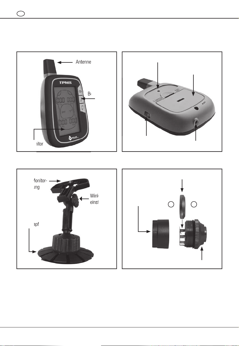
Bedienelemente......................... 6
Installation des LCD-Monitors ............... 7
Installation der Sensoren . . . . . . . . . . . . . . . . . . 7
Bedienungshinweise . . . . . . . . . . . . . . . . . . . . . 8
Funktion der Bedienknöpfe ................. 8
Voreinstellungen ........................ 9
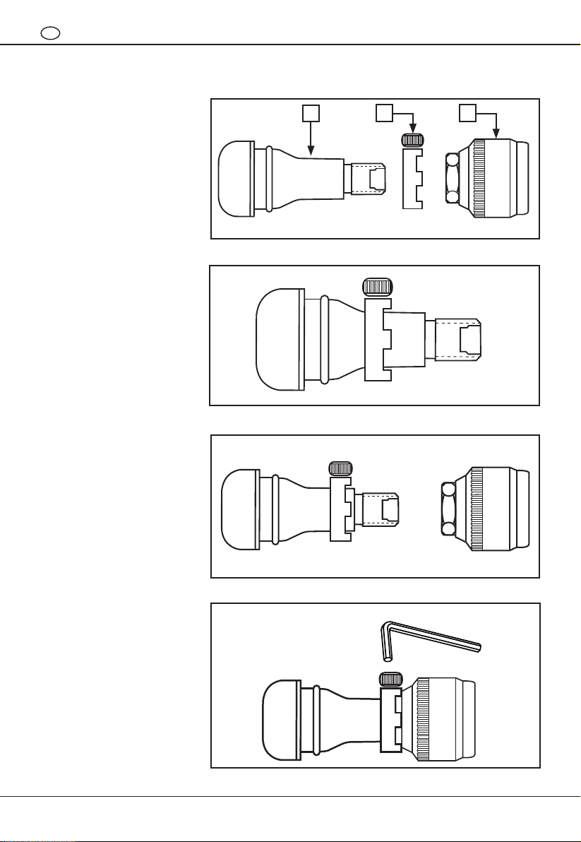
Installation der Diebstahlsicherung . . . . . . . . . . 10
Garantiebedingungen.................... 11
Kunden-Servicecenter ................... 11
GB
Safetyinformation...................... 12
Points for attention...................... 12
Product package information .............. 12
Technical information . . . . . . . . . . . . . . . . . . . 13
Advantages ........................... 13
Productfeatures ....................... 13
Appearance........................... 14
LCD monitor installation procedure . . . . . . . . . . 15
Tire pressure sensor installation . . . . . . . . . . . . 15
Operating instructions . . . . . . . . . . . . . . . . . . . 16
LCD monitor buttons function .............. 16
Pre-setting ........................... 17
Anti theft installation guide ................ 18
Warranty ............................. 19
Costumer service centre . . . . . . . . . . . . . . . . . 19
FR
Informations sur la sécurité . . . . . . . . . . . . . . . 20
Points requérant une attention particulière..... 20
Mentions concernant le produit sur l’emballage 20
Information technique . . . . . . . . . . . . . . . . . . . 21
Avantages ............................ 21
Caractéristiques du produit................ 21
Aspect. . . . . . . . . . . . . . . . . . . . . . . . . . . . . . . 22
Procédure d’installation de l’écran LCD ....... 23
Installation du capteur de pression des pneus . . 23
Instructions de service . . . . . . . . . . . . . . . . . . . 24
Fonctions des boutons de l’écran LCD........ 24
Préréglages........................... 25
Verrouillage de prévention du démontage . . . . . 26
Conditions de garantie . . . . . . . . . . . . . . . . . . . 27
S.A.V................................ 27
NL
Veiligheidsinstructies . . . . . . . . . . . . . . . . . . . . 28
Belangrijke aanwijzingen . . . . . . . . . . . . . . . . . 28
Verpakkingsinhoud . . . . . . . . . . . . . . . . . . . . . 28
Technische aanwijzingen ................. 29
Voordelen............................ 29
Producteigenschappen................... 29
Aanzichten ........................... 30
Installatie van de LCD-monitor . . . . . . . . . . . . . 31
Installatie van de bandenspanningsensor...... 31
Gebruiksaanwijzingen.................... 32
Functies van de LCD-monitortoetsen......... 32
Voorinstellingen ........................ 33
Diefstalbeveiliging . . . . . . . . . . . . . . . . . . . . . . 34
Garantiebepalingen . . . . . . . . . . . . . . . . . . . . . 35
Klantenservice ......................... 35
GR
Veiligheidsinstructies . . . . . . . . . . . . . . . . . . . . 28
Belangrijke aanwijzingen . . . . . . . . . . . . . . . . . 28
Verpakkingsinhoud . . . . . . . . . . . . . . . . . . . . . 28
Technische aanwijzingen ................. 29
Voordelen............................ 29
Producteigenschappen................... 29
Aanzichten ........................... 30
Installatie van de LCD-monitor . . . . . . . . . . . . . 31
Installatie van de bandenspanningsensor...... 31
Gebruiksaanwijzingen.................... 32
Functies van de LCD-monitortoetsen......... 32
Voorinstellingen ........................ 33
Diefstalbeveiliging . . . . . . . . . . . . . . . . . . . . . . 34
Garantiebepalingen . . . . . . . . . . . . . . . . . . . . . 35
Klantenservice ......................... 35

4
DE
Sicherheitsinformationen
Vor Inbetriebnahme des Reifendruckkontrollsystems folgende Punkte bitte aufmerksam lesen und beachten:
Die Position des LCD-Monitors darf die Sicht des Fahrers nicht beeinflussen.•
Stellen Sie sicher, dass der Bildschirm in seiner Halterung vollständig eingerastet ist bevor Sie losfahren.•
Die Fahrsicherheit ist jederzeit zu gewährleisten. Vorsicht beim Bedienen und Überprüfen der Druck- und•
Temperaturangaben.
Zerlegen der Komponenten ist nicht zulässig. Wichtige Einzelteile könnten beschädigt werden.•
Bitte überprüfen Sie, ob die Sensoren dicht aufgeschraubt sind, indem Sie etwas Wasser über den Ventilschaft•
laufen lassen und nach eventuellem Luftaustritt suchen.
Wichtige Hinweise
Bringen Sie vor der Installation den Reifendruck auf den richtigen Stand.•
Bitte stellen Sie sicher, dass der LCD-Monitor die Signale von allen 4 Sensoren empfangen kann.•
Das TPMS verfügt über eine Diebstahlsicherung, die das mutwillige Abschrauben der Sensoren verhindert.•
Die Installation ist optional.
Bitte beachten Sie die Schraubrichtung und das max. Anzugsmoment. Zu festes Anziehen der Sensoren kann•
das Ventilsystem beschädigen.
Die Druckanzeige auf dem LCD-Monitor zeigt Druckveränderungen in 1 psi (0,07 bar) an.•
Alle Komponenten wurden störungsfrei für andere Funksignale gebaut.•
Der LCD-Monitor stellt die Verbindung zu den Sensoren automatisch her. Es ist normal, wenn nicht alle•
4 Sensoren direkt angezeigt werden.
Der Hersteller empfiehlt, nach der Installation der Sensoren die Reifen auswuchten zu lassen.•
Packungsinhalt
Der Lieferumfang des TPMS beinhaltet:
1. LCD-Monitor 1 x
2. Sensoren 4 x
3. CR 1632 3 V Batterie 4 x
4. AAA 1,5 V Batterie 2 x
5. Bedienungsanleitung 1 x
6. Selbstklebender Befestigungsfuß 1 x
7. Diebstahlsicherungsschloss 4 x
8. Innensechskantschlüssel 1 x
9. Anschlusskabel für Zigarettenanzünder 1 x
10. LCD-Monitor Befestigung 1 x
11. Saugnapf 1 x
Vorteile
Erhöht die Fahrsicherheit•
Reduziert den Kraftstoffverbrauch•
Verlängert die Lebensdauer der Reifen•
Echtzeit-Überwachung des Reifendrucks•

5
DE
Technische Angaben
Sensor•
Frequenz: 433.92 MHz Betriebstemperatur: -40°C ~ +125°C
Spannung: 3V DC: <6mA Abmessungen: Ø 20.5 mm x 20 mm
Sensor: 0 – 60 PSI (0 – 4,2 bar)
LCD-Monitor•
Frequenz: 433.92 MHz Betriebstemperatur: -20°C ~ +80°C
Spannung: 3V DC Abmessungen: 91 mm x 73.5 mm x 22 mm
Einstellungsbereich Warnschwellen•
Untere Warnschwelle (Lo.P) 1,1 - 2,48 bar
Obere Warnschwelle (Hi.P) 2,62 - 4,14 bar
Produkteigenschaften
Installation ohne technisches Fachwissen möglich•
Der Sensor wird anstelle der Ventilkappen auf das Reifenventil aufgeschraubt.
LCD-Monitor•
Der LCD-Monitor zeigt den Reifendruck, Temperatur und Batteriestatus an.
Hochauflösende Druckmessung•
Elektronische Messwertaufnahme in Echtzeit. Anzeigegenauigkeit: +/- 1 psi (0,07 bar).
Messwertübertragung•
Die Sensoren übermitteln automatisch aktuelle Druck- und Temperaturdaten.
Batteriestatus Anzeige•
Der LCD-Monitor und jeder einzelne Sensor verfügt über eine Batteriestandwarnung. Der jeweils aktuelle
Batteriefüllstand ist am LCD-Monitor abzulesen.
Diebstahlsicherungsschloss•
Jeder Sensor verfügt über ein Schloss. Es fixiert den Sensor diebstahlsicher am Reifenventil.
Warnung bei ungewöhnlichen Messwerten•
Falls der Reifendruck während der Fahrt unter oder über den eingegebenen Wert sinkt oder steigt, erscheint
eine Warnmeldung auf dem LCD-Monitor und ein akustisches Signal.
Erscheinungsbild•
Der aufgeschraubte Sensor beeinflusst nicht den optischen Gesamteindruck des Reifens. Seine Abmessungen
sind minimal: Ø 20.5 mm, Länge 20 mm.
Patentschutz•
Dieses Produkt ist in USA, Taiwan, China, Europa patentiert.
Die geltenden Schutzrechte beinhalten den Platinenaufbau und die mechanische Funktion. Nachbau und
Verkauf dieses Produktes sind nur mit ausdrücklicher Genehmigung gestattet.

6
DE
Bedienelemente
LCD-Monitor Vorderansicht
LCD-Monitor Befestigung
LCD-Monitor Rückseite
Sensoren
Antenne
LCD-Monitor
Bedienknöpfe
Befestigung für LCD-Monitorhalterung
Anschlussbuchse
Batteriefach
An/Aus-Schalter
LCD-Monitor-
halterung
Winkel-
einstellung
Saugnapf
Batterie
Sensor
Batterie-
kappe
Antenne
LCD-Monitor
Bedienknöpfe
LCD-Monitor-
halterung
Winkel-
einstellung
Saugnapf
–
+

7
DE
Installation des LCD-Monitors
Stromversorgung: Öffnen Sie die Batteriefachabdeckung und legen 2 Alkaline AAA Batterien gemäß den•
aufgedruckten Symbolen ein. Ebenso ist die Stromversorgung mit Hilfe des beigefügten Kabels über den
Zigarettenanzünder möglich.
Gerät einschalten.•
Befestigung der LCD-Monitorhalterung: Die LCD-Monitorhalterung wird unter Verwendung des Saugnapfes•
oder beigefügtem doppelseitigem Klebeband am Armaturenbrett befestigt. Der LCD-Monitor wird an dem
Halterrahmen mit einer Stellschraube am Rückenteil fixiert.
Winkeleinstellung des LCD-Monitors: Der optimale Sichtwinkel des LCD-Monitors kann durch Lösen und•
Arretieren der Justierschraube am Multi-Connector individuell eingestellt werden.
Auf den Kappen der 4 Sensoren steht die jeweilige Reifenposition, in der die Sensoren montiert werden•
müssen. Die Kappen dürfen nicht vertauscht werden.
Die Kürzel auf den Kappen stehen für:•
F.L.: (Front Left) – „Vorne Links“
F.R.: (Front Right) – „Vorne Rechts“
R.L.: (Rear Left) – „Hinten Links“
R.R.: (Rear Right) – „Hinten Rechts“
Installation der Sensoren
1. Legen Sie die Batterie ein. Der Minuspol zeigt dabei zum Sensor. (siehe Abbildung)
Achtung! Die Batteriekappen nicht vertauschen!
2. Setzen Sie das Schloss zur Diebstahlsicherung zuerst auf das Reifenventil
(Zähne zeigen zum Ventilende).
3. Schrauben Sie den Sensor auf das Reifenventil.
4. Positionieren Sie das Schloss mit den Zähnen gegen den Sensor und fixieren Sie es
mit der Sicherungsschraube.
F.R
F.L
R.R
R.L
–
+

8
DE
Bedienungshinweise
Symbole auf dem LCD-Monitor
1. Temperaturanzeige / °C / °F
2. Status des Übertragungssignals der
Sensoren. Wenn eine Verbindung besteht,
zeigt der LCD-Monitor das Symbol 2.
3. Reifendruck- und Temperaturanzeige
4. Lautloser Betrieb. Mute-Symbol
5. Monitorstatus: Blinkt = Normal
Blinkt nicht = Initialisierung
6. Niedriger Batteriestatus des jeweiligen Sensors.
Wenn dieses Symbol erscheint, wechseln
Sie bitte die Batterie am betroffenen Sensor
so schnell wie möglich.
7. Position des Sensors bzw. Zuordnung zum Reifen
8. Druckmessanzeige
9. Niedriger Batteriestatus des LCD-Monitors.
Wenn dieses Symbol erscheint, wechseln Sie bitte
die Batterie des LCD-Monitors so schnell wie
möglich.
Funktion der Bedienknöpfe
Lautlos / Sensor ID / Voreinstellung•
Temperaturanzeige /• +
Beleuchtung /• –
F.L F. R
R.L R.R
°C °F
psi kpa
bar kg/cm2
12
9
3
4
6
5
78

9
DE
Lautlos / Sensor ID / Voreinstellung•
1. Lautlos-Modus. Sobald der Reifendruck außerhalb des normalen Bereichs liegt,wird dieser
Status auf dem LCD-Monitor und mit einem Tonsignal angezeigt. Durch Drücken der
Lautlos-Taste wird das Tonsignal gestoppt.
2. Sensor Erkennungsfunktion.
3. Halten Sie die Lautlos-Taste für einige Sekunden gedrückt, dann schaltet der Monitor auf
den Voreinstellungsmodus um. (siehe Voreinstellung)
Temperaturanzeige /• +
1. Durch Betätigung dieser Taste zeigt der LCD-Monitor alle 4 Reifentemperaturen an. Nach
3 Sekunden schaltet die Anzeige automatisch zurück auf die Reifendruckwerte.
2. Im Zusammenhang mit Voreinstellung: Durch Drücken dieser Taste kann die Tempera-
tureinheit von Celsius auf Fahrenheit umgestellt werden.
3. In Zusammenhang mit Voreinstellungen: Werterhöhung +
Beleuchtung /• –
1. Durch Betätigung dieser Taste schaltet die Beleuchtung für 3 Sekunden ein.
2. Im Zusammenhang mit Voreinstellung: Durch Drücken dieser Taste kann die Druckeinheit
zwischen PSI, KPA, BAR, KG/CM² umgestellt werden.
3. In Zusammenhang mit Voreinstellungen. Einstellung Wertminderung –
Voreinstellungen
• Modus1:DruckeinheiteneinstellenAnzeige:SETUNI
1. mit Lautlos-Knopf in den nächsten Modus umschalten.
2. mit Beleuchtungs-Knopf zwischen den Druckeinheiten wechseln.
• Modus2:TemperatureinheiteneinstellenAnzeige:SETUNI
1. mit Lautlos-Knopf in den nächsten Modus umschalten.
2. mit Temperatur-Knopf zwischen den Temperatureinheiten wechseln.
• Modus3:ReifendruckuntereWarnschwelleeinstellenAnzeige:SETLO.P(LowPressure)26.0PSI
1. mit Lautlos-Knopf in den nächsten Modus umschalten.
2. mit Temperatur-Knopf den Wert erhöhen. +
3. mit Beleuchtungs-Knopf den Wert herabsetzten. –
• Modus4:ReifendruckobereWarnschwelleeinstellenAnzeige:SETHI.P(HighPressure)45.0PSI
1. mit Lautlos-Knopf in den nächsten Modus umschalten.
2. mit Temperatur-Knopf den Wert erhöhen. +
3. mit Beleuchtungs-Knopf den Wert herabsetzten. –
• Modus5:SensortemperaturobereWarnschwelleeinstellenAnzeige:SETHI.T(HighTemperature)70.0°C
1. Einstellmodus beenden.
2. mit Temperatur-Knopf den Wert erhöhen +
3. mit Beleuchtungs-Knopf den Wert herabsetzten. –

10
DE
Installation der Diebstahlsicherung
1. Ventil
2. Schloss
3. Sensor
C. Benutzen Sie den Sechskant-
schlüssel um das Schloss (2) am
Ventil (1) zu fixieren.
B. Schrauben Sie den Sensor (3)
auf das Ventil (1).
A. Schieben Sie das Schloss (2)
auf das Ventil (1).
12 3
A
B
C

11
DE
Garantiebedingungen
In Übereinstimmung mit den gesetzlichen Vorschriften unterliegt dieses Gerät einer Garantiezeit von 24 Monaten,
beginnend mit dem Kaufdatum. Eine Kopie der Verkaufsquittung genügt als Nachweis in einem Reklamationsfall
im Rahmen der Garantie. Schäden, die auf normalen Verschleiß, Transport, Überladung,
Nichtbeachtung der
Zusammenbau-/Betriebs
anweisungen oder unsachgemäße Behandlung zurückzuführen sind, werden durch die
Garantie nicht abgesichert. Dasselbe gilt für Verschleißteile. Der Hersteller ist nicht haftbar für indirekte Folgen
und Sachschäden. Die Garantiezeit wird durch etwaige Reparaturen nicht erneuert oder verlängert. Ansprüche
im Rahmen der Garantie werden nur anerkannt, wenn das Gerät in einem kompletten Zustand und portofrei an
den Hersteller, Vertrieb oder an das unten angegebene Service-Center eingesandt wird.
EG-Konformitätserklärung
Dieses Produkt entspricht in seiner Konstruktion und in seinem Betriebsverhalten den zutreffenden europäischen
Richtlinien sowie ggf. ergänzenden nationalen Anforderungen. Die Konformität wurde nachgewiesen.
Die Konformitätserklärung steht Ihnen im Internet unter www.atrium-enterprises.eu zur Verfügung oder kann bei
folgender Adresse angefordert werden:
Atrium Enterprises GmbH
Zum Pier 72
D-44536 Lünen
Germany
Kunden-Servicecenter
Falls es nicht möglich ist, das Gerät bei einer Reklamation im Rahmen der Garantie, bei einem Geräteversagen
oder bei dem Bedarf eines Ersatzteils an den Lieferanten zurückzugeben, dann wenden Sie sich an folgende
Adresse:
Atrium Enterprises GmbH
Zum Pier 72
D-44536 Lünen
Germany
Tel.: +49 - (0)2 31 / 8 09 01-0
Fax: +49 - (0)2 31 / 8 09 01-1 11

12
GB
Safety information
Before installation, please review the following reminders:
Please mount the LCD monitor in a place that will not affect the driver’s vision.•
Make sure the LCD monitor is properly mounted to avoid dropping off during driving.•
Take care of the driving safety, when you check the LCD monitor pressure / temperatures figures.•
Do not disassemble or attent to service this TPMS, since the components might be damaged.•
Checking the air leakage after screwing the sensors by spreading some detergent water on value stem.•
Points for attention
Please make sure the LCD monitor can receive the signals from all 4 tires‘ pressure sensors.•
The TMPS sensors are equiped with disassembly prevention locks. The installation is optional.•
Please pay attention to the screwing direction and force. Too much force might damage the tires‘ valve stem.•
The showing figures on the LCD monitor will variations from 1 psi (0,07 bar).•
All of the devices had been manufactured to avoid frequency disturbances.•
After the vehicle is switch on all sensors will start indication as soon as the vehicle is moving.•
The manufacturer advises to consult a specialist for wheel balances.•
Product package information
The TPMS sets´s items as follows:
1. Tire pressure LCD monitor 1 x
2. Tire pressure sensor 4 x
3. CR 1632 3 V battery 4 x
4. AAA 1.5 V battery 2 x
5. User’s Guide 1 x
6. Glue plate 1 x
7. Disassembly prevention lock 4 x
8. Allan key 1 x
9. Vehicle power cable set 1 x
10. LCD monitor fixing frame 1 x
11. Suction plate 1 x
Advantages
Ensure the safety of vehicle movement•
Reduce fuel consumption•
Enhance tire lifetime•
Real-time monitoring tire pressure•

13
GB
Technical information
Sensor•
Frequency: 433.92 MHz Operating temperature: - 40°C ~ +125°C
Voltage: 3V DC: <6mA Dimensions: Dia. 20.5 mm x 20 mm
Sensor: 0 – 60 PSI (0 – 4,2 bar)
Monitor Receiver•
Frequency: 433.92 MHz Operating temperature: -20°C ~ +80°C
Voltage: 3V DC Dimensions: 91 mm x 73.5 mm x 22 mm
Warning range•
Low pressure (Lo.P) 1,1 - 2,48 bar
High pressure (Hi.P) 2,62 - 4,14 bar
Product features
D.I.Y. (Do-it-yourself) installation•
Just screw the sensors onto the value stems as replacement for the valve stem caps.
LCD•
LCD showing the tires pressure, temperature and battery power.
High resolution tire pressure detection•
Electronic type of tire pressure detection. Detection precision from + /- 1 psi (0,07 bar).
Transmission status display•
The sensors will automatically transmit pressure / temperature data to the LCD monitor.
Battery power status display•
LCD and each single tire pressure sensor has a low battery warning. When LCD monitor or tire pressure sensor
is in low battery power, the user can check the battery power status from LCD monitor.
Disassembly prevention lock•
Each tire pressure sensor is provided with a disassembly prevention lock. It fixes the tire pressure sensor on
the valve stem.
Abnormal warning•
While the vehicle is on the move, should the tire pressure gets abnormal, lower or to high than the preset
standard, the LCD monitor will send the warning message immediately.
Aesthetic in appearance•
When the sensor is screwed on the tire, it would not affect whole tire appearance. The dimension of tire pres-
sure sensor is Dia. 20.5 mm x L 20 mm.
Multinational patents•
This product is patented in US, Taiwan, China, Europe. The patents included PC board circuit design and
mechanical design. It must not be copied or sold without authorization.

14
GB
LCD monitor front view
Fixing frame
LCD monitor back view
Tire pressure sensor
Antenna
LCD monitor
Interface
Fixing frame position
Vehicle power jack
Battery cover
Power switch
LCD monitor
fixing frame
Angle
adjustment
Suction cap
Battery
Sensor
Battery cap
Appearance
–
+
Multi-
Connector

15
GB
LCD monitor installation procedure
Power installation: Please prepare two of AAA alkaline battery, open the battery cover and following the dia-•
gram to install the battery. Connection via the cigarette lighter socket also possible.
Switch on LCD monitor.•
Fixing frame installation: There are „glue plate“ and „suction plate“ inside the package you can use either one•
to fix the frame. Please connect the multi-connector to the „glue plate“ or the „suction plate“ and then fix the
„Frame“ to the back of the monitor.
While you are installing the sensors, don’t mix up the sensor caps.•
The tire’s position diagram as follows:•
F.L. means „Front Left Tire“
F.R. means „Front Right Tire“
R.L. means „Rear Left Tire“
R.R. means „Rear Right Tire“
Tire pressure sensor installation
1. Install the battery. Attention: the negative pole must face the open end
of the sensor. Don’t mix up the batteries caps!
2. Install the disassembly prevention lock to the tire valve stem.
Teeth facing the end of the valve.
3. Install the tire pressure sensor on the correct valve.
4. Please use the special key to open and lock the screw.
–
+
F.R
F.L
R.R
R.L

16
GB
Operating instructions
LCD monitor icon indication
1. Temperature / °C / °F
2. Tire pressure sensor signal transmission status.
3. Tire pressure and temperature figures.
4. Mute mode icon.
5. Monitor status:
blinking = normal,
no blinking = booting
6. Low battery icon. When this icon shows up,
change sensor battery as soon as possible.
7. Tire pressure sensors position.
8. Pressure unit
9. LCD monitor battery low power icon.
When this icon shows up, change LCD monitor
battery as soon as possible.
LCD monitor buttons function
Mute / Sensor I.D. / Pre-setting•
Temperature /• +
Backlight /• –
F.L F. R
R.L R.R
°C °F
psi kpa
bar kg/cm2
12
9
3
4
6
5
78

17
GB
Mute / Sensor I.D. / Pre-setting•
1. This button is designed to switch to mute mode. While tire pressure is getting abnormal,
the abnormal status will show up on LCD monitor with beep. Press this mute button to
stop the beep.
2. This button will also enter the sensor I.D. learning feature.
3. Press mute button for a few seconds, then the monitor will enter into the pre-setting
mode.
Temperature /• +
1. This is for tire temperature display.When this button is pressed, the LCD monitor will show
all tires‘ temperature figures after 3 seconds, it will keep showing tires‘ pressure figures.
2. Press this button to choose the temperature as Centigrade or Fahrenheit in mode
function.
3. Press temperature button to increase values in mode function.
Backlight /• –
1. This is turning on backlight will be lighting for 3 seconds and turn off automatically.
2. Press this button to choose pressure unit as PSI, KPA, BAR, KG/CM² in mode function.
3. Press backlight button to decrease values in mode function.
Pre-setting
Mode 1: Setting pressure units• Shows: SET UNI
1. Press button mute into the next mode.
2. Press button backlight to switch pressure units.
Mode 2: Setting temperature units• Shows: SET UNI
1. Press button mute into the next mode.
2. Press button temperature to switch temperature units.
Mode 3: Setting low pressure• Shows: SET LO.P 26.0 PSI
1. Press button mute into the next mode.
2. Press button temperature to increase the setting figure. +
3. Press button backlight to decrease the setting figure. –
Mode 4: Setting high pressure• Shows: SET HI.P 45.0 PSI
1. Press button mute enter into the next mode.
2. Press button temperature to increase the setting figure. +
3. Press button backlight to decrease the setting figure. –
Mode 5: Setting the high temperature• Shows: SET HI.T 70.0°C
1. Close the setting mode.
2. Press button temperature to increase the setting figure. +
3. Press button backlight to decrease the setting figure. –

18
GB
Anti theft installation guide
1. Valve
2. Lock
3. Sensor
3. Use the special key to fix the
lock (2) to the valve (1).
2. Fasten the sensor (3) onto the
valve stem (1).
1. Place the lock (2) onto the
valve stem (1).
12 3

19
GB
Warranty
In line with statutory regulations this appliance has a 24 month warranty, starting from the date of purchase. A
copy of the sales receipt is sufficient proof in the event of a claim subject to warranty. Damage due to regular
wear, transport, overloading, failure to observe the instructions of assembly / operation or the improper handling
are not covered by the warranty. The same applies to wear parts. The manufacturer is not liable for indirect con-
sequences and damage to property.The period of warranty is not renewed or extended following possible repairs.
Claims under warranty are only recognised if the complete appliance is sent, shipping paid, to the manufacturer,
the distributor or the services centre listed below.
EU – Declaration of conformity
In the declaration of conformity the manufacturer declares that the product is in conformity with the essential
requirements of the directive 1999/5/EC of the european parliament and of the council.
The declaration of conformity is available on the Internet at www.atrium-enterprises.eu or can be request at the
following address:
Atrium Enterprises GmbH
Zum Pier 72
D-44536 Luenen
Germany
Costumer service centre
If it is not possible to return the appliance to the supplier in the event of a claim subject to warranty, a failure of
the appliance or if a spare part is required, please refer to the following address:
Atrium Enterprises GmbH
Zum Pier 72
D-44536 Luenen
Germany
Tel.: +49 - (0)2 31 / 8 09 01-0
Fax: +49 - (0)2 31 / 8 09 01-1 11
E-Mail: [email protected]

20
FR
Informations sur la sécurité
Avant l’installation, veuillez tenir compte des éléments suivants :
Veuillez monter l’écran LCD à un emplacement où il n’entravera pas la visibilité du conducteur.•
Assurez-vous que l’écran LCD est monté correctement pour empêcher qu’il ne chute pendant le trajet.•
Veillez à la sécurité routière lorsque vous consultez les données de pression / de température sur l’écran•
LCD.
Ne pas démonter ou procéder à la maintenance de ce TPMS car vous risquez d’endommager certains•
composants.
Vérifier les fuites d’air après le vissage des capteurs en répandant de l’eau savonneuse sur l‘indicateur.•
Points requérant une attention particulière
Assurez-vous que l’écran LCD est en mesure de réceptionner les signaux de tous les capteurs de pression•
des quatre pneus.
Les capteurs TMPS sont équipés de verrouillages de prévention de démontage. L’installation est disponible•
en option.
Veuillez faire attention à la direction et à la force de vissage. Trop de serrage risque d’endommager la tige de•
soupape des pneus.
Le indications affichées sur l’écran LCD seront actualisées en cas de survenue d’un changement de 1 psi•
(0,07
bar)
.
Tous les dispositifs ont été fabriqués pour éviter toute perturbation de fréquences.•
Une fois que vous avez allumé le véhicule, si l’un des capteurs n’est pas encore connecté, vous ne devez pas•
vous faire de souci car une fois que le véhicule se déplacera, il se connectera automatiquement.
Le fabricant recommande de consulter un spécialiste dans le domaine des équilibreuses de roues.•
Mentions concernant le produit sur l’emballage
Le TPMS configure les éléments de la manière suivante:
1. L’écran LCD 1 x 7. Verrouillage de prévention du démontage 4 x
2. Capteur de pression des pneus 4 x 8. Clé Allan 1 x
3. CR 1632 3 V batterie 4 x 9. Jeu de câbles d’alimentation du véhicule 1 x
4. AAA 1.5 V batterie 2 x 10. Support de fixation pour l’écran LCD 1 x
5. Guide d’utilisation 1 x 11. Plaque à succion 1 x
6. Panneau colle 1 x
Avantages
Assure la sécurité des mouvements du véhicule•
Réduit la consommation de carburant•
Accroît la durée de vie du pneu•
Contrôle en temps réel de la pression du pneu•
Table of contents
Languages:
Other Atrium Measuring Instrument manuals