Atronix AX Series User manual

INVERTER
atx009de-en0823
Installation and operating instructions
AX series, 1ph
Machine Translated by Google

Operating instructions
a-TroniX inverter AX series, 1ph
Our EU declaration of conformity and warranty conditions can be found on:
Read this instruction manual carefully before installation.
www.a-tronix.de
It contains important regulations and information for the use of this product and
provides technical support for the operator of the device.
All rights reserved.
AKKU SYS Accumulator and Battery Technology Nord GmbH
AKKU SYS Akkumulator- und Batterietechnik Nord GmbH cannot be held responsible for
any inaccuracies or inappropriate information in these operating instructions. The information
in this document can be read without
Connection path 23 D-25469 Halstenbek · GERMANY
may be changed with prior notice, but there is no obligation to continually update it.
Design and equipment changes that improve the production process
Telephone +49 4101 37676-0 · Fax +49 4101 85475-66
or the product are reserved.
Read carefully before use!
5
2.1 Intended use 2.2 PE connection and
leakage current 6
2.3 Surge Protection Devices (SPDs) for PV Installation 3.
Introduction
3.1 Basic Features
8th
3.2 Dimensions
Page
9
3.3 Inverter terminals
4
9
4
10
4
11
4
1. Notes about this manual
5
1.1 Scope 1.2 Target
group 1.3
Symbols used 2. Security
INTRODUCTION
The publication and copyright of this documentation remain with the company:
Table of contents
Page 2 atx009de0823
Machine Translated by Google

Operating instructions
a-TroniX inverter AX series, 1ph
atx009de0823 Page 3
4.2 Battery
6.6 EPS connection
4.3 AC Output/Input 4.4 EPS
Output 4.5 Efficiency
and Protection
6.7 System connection diagrams 6.8
Commission the inverter
4.6 General data 5.
Installation
6.9 Switch off the inverter
4. Technical data
5.1 Check for physical damage 5.2 Packing
list
7. Operation
7.1 Control panel
5.3 Assembly
7.2 Function tree
6. Electrical connection
8.
Maintenance 8.1 Overview of error codes
6.1 PV connection (only for hybrid)
8.2 Troubleshooting and routine maintenance 9.
Decommissioning 9.1 Dismantling the
inverter 9.2
Packaging 9.3 Storage and transportation
6.2 Connecting the battery
4.1 PV input (only for hybrid)
6.3 AC connection 6.4
Ground connection 6.5
Installation of a communication device (Optional)
14
13
20
37
45
17
12
36
45
33
16
44
39
15
26
37
22
14
20
12
36
45
12
45
16
35
16
26
39
23
38
Machine Translated by Google
1.Notes about this manual
CAUTION!
WARNING!
Failure to take preventative protective measures could potentially result in damage
to the product and/or its functions or to something in its surroundings.
This section explains the symbols that appear on the inverter and on the
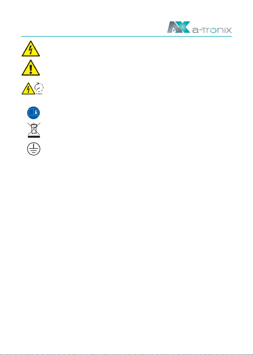
This symbol indicates a hazardous situation which, if not avoided, could result in
serious injury or death.
A NOTICE
Type plate shown are:
Be careful of hot surfaces. The inverter can become hot during operation. Avoid
touching during operation.
A NOTICE:
Please keep these instructions so that they are accessible at all times.
The inverter complies with the requirements of the applicable CE guidelines.
DANGER!
This symbol indicates texts, hints or tips.
1.1 Scope
1.2 Target group
1.3 Symbols used The
following types of safety warnings and general information
appear in this document as described below:
AX3.0kW-1ph, AX3.7kW-1ph, AX4.6kW-1ph, AX5.0kW-1ph, AX6.0kW-1ph
be performed.
This manual describes the assembly, installation, commissioning, maintenance and
troubleshooting for the following models of the a-TroniX products:
This manual is intended for qualified electricians. All tasks described may only be
carried out by a qualified electrician
atx009de0823
page 4
Machine Translated by Google
and comply with regulations.
Protective conductor connection
• Check the device before installation to ensure there are no
Danger due to high voltages.
Has transport damage that could affect the integrity of the insulation or the safety
distances. Choose the installation location carefully
Danger to life due to high voltages in the inverter!
Danger.
and comply with prescribed cooling requirements. Unauthorized removal of
necessary protective devices, improper use, incorrect
The inverters of the a-TroniX series AX were developed and tested in accordance
with international safety requirements. However, certain safety precautions must be
taken when installing and operating this inverter. The installer must read and follow
all instructions, safety notices and warnings in this installation manual.
Installation and operation may result in serious safety hazards, electric shock
hazards, or equipment damage.
Danger of electric shock!
• All work, including transport, installation, commissioning and maintenance,
• Consult before connecting the inverter to the power grid
Danger to life due to high voltages.
must be carried out by qualified, trained personnel.
the local network operator to obtain the appropriate permits.
There is a residual voltage in the inverter that takes 5 minutes to discharge.
Wait 5 minutes before opening the top lid or the DC lid.
• The electrical installation and maintenance of the inverter must be carried out by a
This connection may only be made by qualified specialist personnel.
be carried out by a qualified electrician and in accordance with local regulations
Read the manual.
The product must not be disposed of as household waste.
page 5
atx009de0823
2. Security
2.1 Intended use
Machine Translated by Google

The capacity that can contribute is the internal capacity of the inverter compared to
PE and external protective elements such as the lighting protection.
• During operation, the DC bus is connected to the AC network via the inverter. As a
result, part of the alternating voltage amplitude reaches the intermediate circuit.
The fluctuating tension is constantly changing
• Do not use the device if abnormalities are detected. Avoid
the state of charge of the parasitic PV capacitor (i.e. capacity to PE). This
• Do not install the device in unfavorable environmental conditions, such as
Make temporary repairs.
is associated with a displacement current that is proportional to the capacity and
• Only approved spare parts may be used for all repairs
e.g. B. in the immediate vicinity of flammable or explosive substances, in a corrosive
or desert-like environment, at extremely high or low temperatures
or in high humidity.
the applied voltage amplitude.
according to their intended use and by a licensed professional
• In every PV system, several elements contribute to the leakage current to protective
earth (PE). These elements can be divided into two main types.
• Do not use the device if the safety devices are not working.
or an authorized AKKU SYS service representative.
• Capacitive leakage current: The leakage current is mainly caused by the parasitic
• Residual current: In the event of an error, e.g. B. a defective insulation, where an under
kidney or are deactivated.
• Liability for commercially available components lies with the respective manufacturer
Capacity of the PV modules compared to PE. The module type, the environmental
conditions (rain, humidity) and even the distance of the modules from the roof
A live cable that comes into contact with a grounded person will flow
an additional current called residual current.
• Use personal protective equipment during installation, including
delegated.
can influence the discharge current. Other factors contributing to parasitic
Gloves and eye protection.
• Inform the manufacturer of any non-standard installation conditions.
The residual current factors of PV systems
• Whenever the inverter has been disconnected from the public grid, leave
Please use extreme caution as some components may retain sufficient charge
to create a risk of electric shock. Before touching any part of the inverter, please
make sure that the surfaces and devices are free of dirt
high temperatures or voltage potentials before proceeding.
2.2 PE connection and leakage current
page 6 atx009de0823
Machine Translated by Google

atx009de0823 Page 7
Installing and selecting an external RCD circuit breaker
Residual current device (RCD)
• Installations where local electrical codes require an RCD circuit breaker with a
lower leakage current rating may result in the external RCD circuit breaker being
accidentally tripped due to the discharge current. The following steps are
recommended to avoid unwanted tripping of the external RCD circuit breaker:
However, the inverter automatically resets when the fault currents
are low, manual reset can be saved.
Speed 300mA per unit.
1. Selecting a suitable RCD circuit breaker is important for the correct operation
of the system. An RCD circuit breaker rated at 30mA
can trigger with a leakage current of 15mA (according to IEC 61008).
• In some countries an external RCD circuit breaker is required. The installer must
check which type of RCD circuit breaker is available in the respective local area
• All a-TroniX inverters are equipped with a certified internal residual current
protective device (RCD) that protects against a possible malfunction in the event
of a malfunction of the PV generator, cables or inverter (DC).
High-quality RCD circuit breakers usually trip at a value that
regulations are required. The installation of an RCD circuit breaker must
is closer to its nominal value.
Protects against electric shock. The residual current protection device in the a-
TroniX inverter can detect leaks on the DC side. There are 2 trigger thresholds for
always be carried out in accordance with local regulations and standards.
2. Configure the trip current of the internal RCD circuit breaker
the FI circuit breaker, as required in the DIN VDE 0126-1-1 standard. A low one
a-TroniX recommends using a type A RCD circuit breaker. a-TroniX
Inverter to a lower value than the tripping current of the external RCD circuit
breaker. The internal RCD circuit breaker trips when the
recommends an RCD circuit breaker with a value between 100mA and 300mA,
Threshold serves to protect against rapid changes in leakage, as in
Current exceeds the permissible value. Because the internal RCD circuit breaker
unless local regulations require a lower value.
occur when people come into direct contact. A higher threshold is used for slowly
increasing leakage currents to reduce the current in grounding conductors
to limit security. The default value for higher speed personal protection is 30mA
and lower for fire protection
Machine Translated by Google

page 8 atx009de0823
2.3 Surge protection devices
(SPDs) for PV installation
WARNING!
Induced surges are the most likely cause of lightning damage in the majority of installations,
particularly in rural areas where power is typically supplied via long overhead power lines.
Surges can affect both the PV generator line and the AC cables leading to the building.
Lightning protection professionals should be consulted for final application. With suitable
external lightning protection, the impact of a direct lightning strike on a building can be
weakened in a controlled manner and the lightning current can be diverted into the ground.
The installation of SPDs to protect the inverter from mechanical damage and excessive
stress includes a surge arrester in the case of a building with an external lightning protection
system (LPS) when a separation distance is maintained. To protect the DC system, a surge
protection device (SPD Type2) should be installed at the end of the DC wiring of the inverter
and on the array between the inverter and the PV generator when the voltage protection
level (VP) of the surge arresters is greater than 1100V, an additional SPD type 3 is required
for overvoltage protection for electrical devices.
The formation of loops in the system must be avoided. This short routing and bundling
requirement includes all associated ground bundling conductors.
To protect the AC system, surge protective devices (SPD Type2) should be installed at the
main input point of the AC supply (at the load cutout), which is located between the inverter
and the meter/distribution system; SPD (test pulse D1) for signal line according to EN
61632-1. All DC lines should be laid as short as possible; plus and minus lines of the string or
the main DC supply should be bundled.
When installing the PV system, surge protection with surge arresters should be
provided. The grid-connected inverter is not equipped with SPDs on either the PV input side
or the grid side.
Spark gap devices are not suitable for use in DC circuits once they are conductive; they only
stop conducting when the voltage across their terminals is typically below 30 volts.
Lightning causes damage either from a direct strike or from surges due to a nearby strike.
Machine Translated by Google

3. Introduction
System advantages:
atx009de0823 Page 9
3.1 Basic properties
The high-quality inverters of the AX series are used to convert solar energy into
alternating current and store energy in the battery. The inverter can be used to
optimize self-consumption, to store in the battery for later use or to feed into the
public grid. The working mode depends on the PV energy and user's preferences.
• Advanced anti-islanding solutions.
• Max. efficiency up to 97.8%. EU efficiency up to 97.0%. THD <3%.
Touch buttons.
• Power factor control. User-friendly HMI.
• PC remote control.
• Safety & Reliability:
• Advanced DSP control technology.
• LED status indicators.
Transformerless design with software and hardware protection.
• Uses the latest high-efficiency power component.
• Protection class IP65.
• Export limitation (CT/Meter/DRM0/ESTOP).
• LCD display technical data, human-machine interaction through four
Machine Translated by Google
Working mode
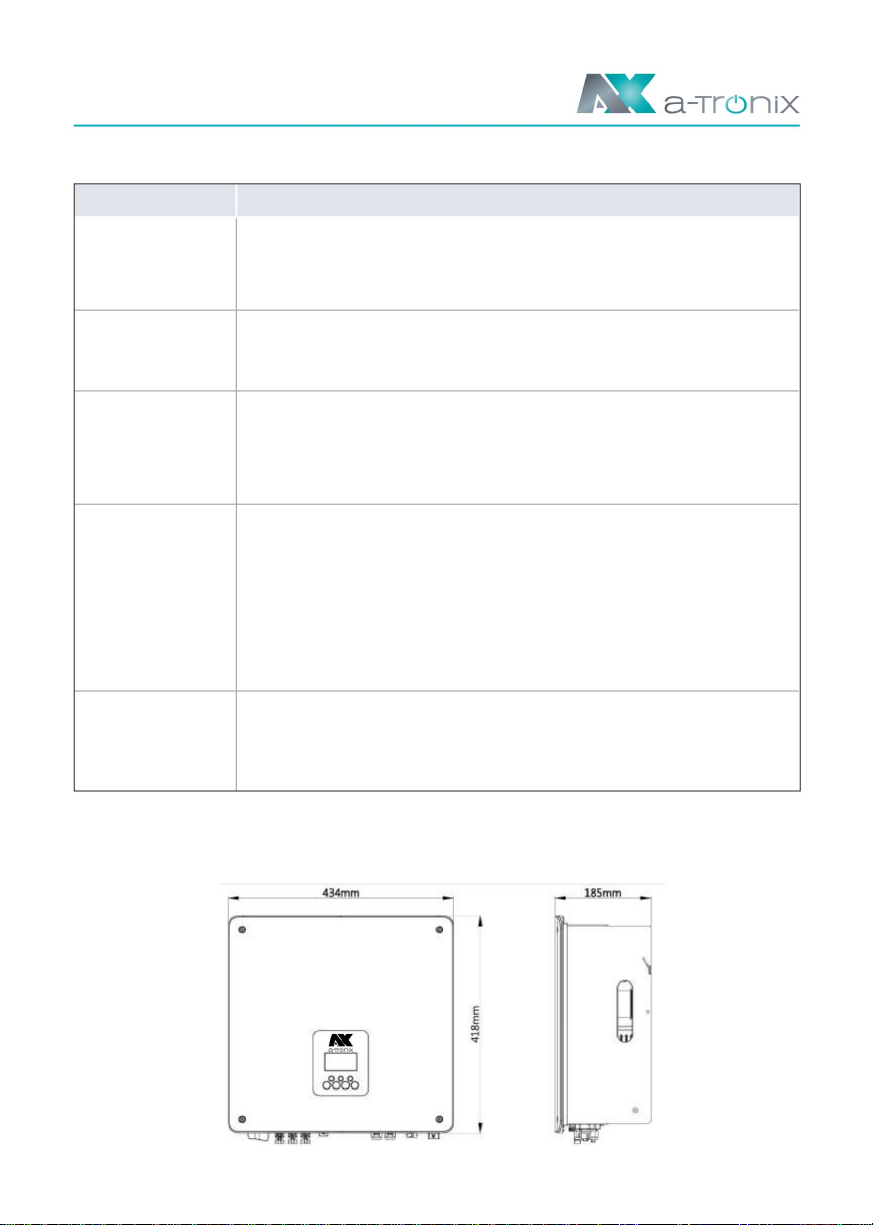
3.2 Dimensions
If there is no PV feed-in, the battery first discharges for local
loads. The battery is charged when an excess of electricity
from other generation sources is detected.
Priority: Load > Battery >
Grid The energy generated by the PV system is used to
optimize self-consumption. The excess energy is used to
charge the batteries and then exported to the grid.
Working mode description
When the grid is off, the system supplies emergency power from
the PV system or battery to power the loads in the house (the
battery is required in EPS mode).
Priority: Load > Grid > Battery
In the case of the external generator, the electricity generated is
first used to supply local consumers and then fed into the public
grid. The battery is charged with the redundant current.
Backup
Priority: Battery > Load > Mains (when charging)
mode
Priority: Load > Battery > Mains (when discharging)
This mode applies to the area in which the electricity price lies
between peak and trough. The user can use off-peak power to
charge the battery.
feed-in
priority
Own consumption
(with
time use
PV power)
force The charging and discharging time can be set flexibly, and you
can also choose whether to charge from the mains or not.
Own consumption
(without
PV power)
atx009de0823
Page 10
Machine Translated by Google
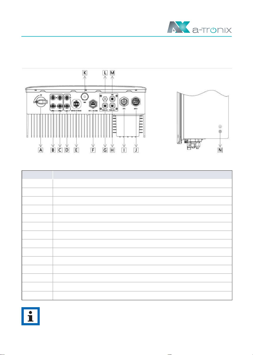
3.3 Inverter terminals
atx009de0823 Page 11
Description
EPS
G
DC switch (only for hybrid)
GRID
PV1 (Only for Hybrid)
H
I
Article
PV2 (Only for Hybrid)
Waterproof lock valve
J
Battery connections
DRM
Measuring device / CT / RS485
Grounding screw
L
M
PARALLEL 1
N
PARALLEL 2
D
A NOTICE:
Only authorized personnel are allowed to establish the connection.
E
A
F
K
b
WiFi/4G/USB
C
BMS
Machine Translated by Google

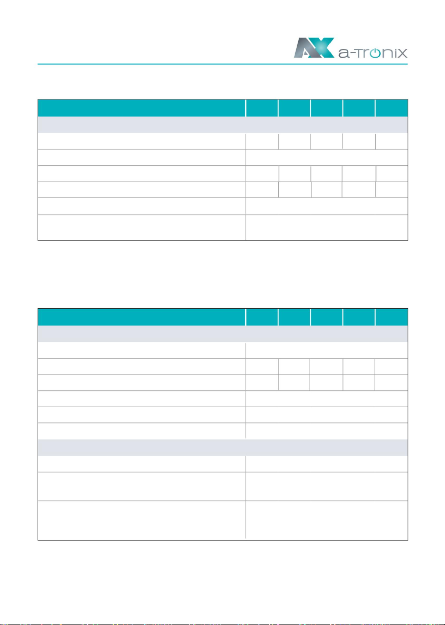
Model AX, 1ph
battery
PV
Model AX, 1ph
Max. DC voltage [V]
20/20
Operating temperature [°C]
360
Max. input current (input A / input B) [A]
80-550
Battery voltage range [V]
Yes
Max. regenerative current of the inverter
2
Battery type
Max. charging current [A]
-20 ~ +50
MPPT voltage range [V]
Optional
LFP
CAN/RS485
Max. recommended DC power [W]
16/16
Strings per MPP tracker
300Vdc
Reverse polarity protection
Nominal DC operating voltage [V]
0
600
40
Storage temperature [°C]
Max. short-circuit current (input A / input B) [A]
100
Recommended battery voltage [V]
-10 ~ +50
to array [mA]
1
Max. discharge current [A]
Switch-on voltage [V]
Number of MPP trackers
80-480
Communication interfaces
DC switch
40
Operating instructions
a-TroniX inverter AX series, 1ph
3kW 3.7kW 4.6kW 5kW 6kW
3kW 3.7kW 4.6kW 5kW 6kW
4. Technical data
4.1 PV input (only for hybrid)
4.2 Battery
A:2250
B:2250
75005500 A:3750A:2750 B:3750B:2750
9000
6900 A:4500
A:3450 B:4500
B:3450
4500
page 12 atx009de0823
Machine Translated by Google

4.3 AC output/input
AC rated power [VA]
Maximum
Max. AC power [VA]
3000
20.9
15.0
47.7
6000
45.5 54.5
3680
Nominal mains frequency [Hz]
9.6A@50us
Output overcurrent protection [A]
7680
4600
Max. AC current [A]
36.7
25.0
Total harmonic distortion
9200
5000
Max. output residual current [A]
0.8 leading to 0.8 lagging
10000
Max. AC apparent power [VA]
6000
50 / 60, ±5
13.6
35
Max. AC current [A]
12000
3300
Nominal mains voltage
(AC voltage range) [V]
23.0
16.7
57.4
27.3
4048
AC rated current [A]
130A@ 10us
22.7
Displacement power factor
34.9
AC inrush current [A]
45.8
27.3
(THDi, nominal power)
41.8
5500
220 / 230 / 240 (180 to 270)
<3%@ rated power
6600
18.4 30
AC INPUT
Model AX, 1ph
AC OUTPUT
6kW
3kW 3.7kW 4.6kW 5kW
4600
Page 13
atx009de0823
Machine Translated by Google
4.4 EPS output
4.5 Efficiency and Protection
3kW 3.7kW 4.6kW 5kW 6kW
3kW 3.7kW 4.6kW 5kW 6kW
Page 14 atx009de0823
Model AX, 1ph
Model AX, 1ph
EPS OUTPUT (WITH BATTERY)
EFFICIENCY
DEFAULT
(THDv, linear load)
<10
G99 / EN50549-1 / CEI 0-21 /
3680 4600
27.3
96.30% 96.33%
EMC
3000
22.7
97.08% 97.08%
EPS nominal voltage [V], frequency [Hz] 220/230/240VAC, 50/60
3600
Euro efficiency
97.04%
EN 62109-1/ EN 62109-2
6000
Max. EPS current [A]
Total harmonic distortion
97.00%
IEC EN 61000-6-3/IEC EN 61000-6-4
16.7
<2%@ rated power
95.26% 95.70%
Max. battery charging power (PV to BAT) (@full load)
VDE-AR-N 4105 and so on
6000
20.9
96.23%
Standby consumption [W]
Certification
Max. EPS power [VA] 5000
<20ms
MPPT efficiency
97.01% 97.08%
Security
EPS peak power (60s) [W] 4400 5500
13.6
MPPT efficiency
98.50%
IEC EN 61000-6-1/ IEC EN 61000-6-2/
7200
99.90%
Switching time [s]
Max. Battery Discharge Power (BAT to AC) (@Full Load)
Machine Translated by Google

4.6 General data
Altitude [m]
Storage temperature [°C]
Naturally
Ingress protection
Noise emission (typical) [dB] Overvoltage
category
Not isolated
Protection class
0% ~ 100 (non-condensing)
Cooling concept Art
LCD, app, website
<2000
Inverter topology
IP65 (for outdoor use)
WLAN / LAN / 4G /GPRS (optional),
I
<35
Dimensions (W x H x D) [mm]
DRM, USB, CT
III (AC), II (DC)
Net weight [kg]
communication
Humidity [%]
LCD display
434*418*185
22
-40 ~ +70
Model AX, 1ph
MEASURES AND WEIGHT
AMBIENT LIMIT
3kW 3.7kW 4.6kW 5kW 6kW
Operating temperature range d. Inverter [°C] -25 ~ +60 (derating at +45°C)
atx009de0823 Page 15
Machine Translated by Google
C
K
A NOTICE:
D
L
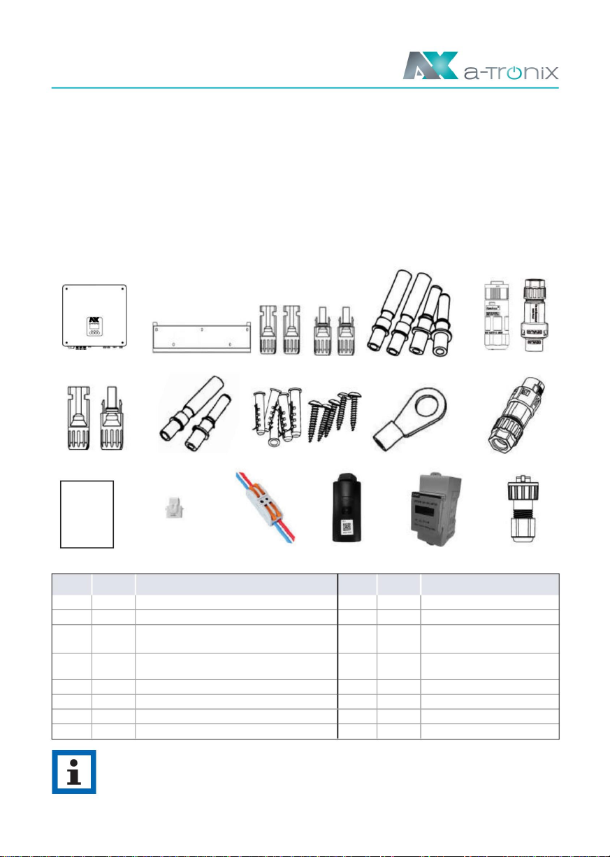
Only use the components included in the scope of delivery
E
M
Installation.
F
N
If there is visible damage, such as: B. Cracks, please contact your dealer immediately.
G
O
H
P
Open the package and take out the product, please check the accessories first. The packing list is shown below.
IJ
A b
Page 16 atx009de0823
Battery connections (1*positive, 1*negative)
PV pin contacts (only for hybrid)
(2*positive, 2*negative)
Measuring device (optional)
CT extension plug
Installation Guide
5. Installation
Expansion tubes & expansion screws
Quick installation guide
Object quantity description
CT (with 10m cable)
Ground connection
Object quantity description
Communication port
Brackets
AC connections
Inverter
PV connections (only for hybrid)
(2*positive, 2*negative)
RJ45
5.2 Packing list
5.1 Check for physical damage
Make sure that the inverter was undamaged during transport.
1
1
A
2
1
E
L
Battery pin contacts (1*positive, 1*negative) O
I
G
1
N
K4
4
P
1
21 WLAN / LAN / 4G (Optional)
b
D
5
1
F
M
J
C
H
1
1
1
2
Machine Translated by Google

• The wall on which the inverter hangs should meet the following conditions:
300300
mmmm
is not enough (e.g. wooden wall, wall covered with a thick decorative layer).
B. The inverter needs to be supported or reinforced if the strength of the wall
5.3 Assembly
atx009de0823 Page 17
No SunlightImpact of rain No Impact of rain
Not a direct one snow formation
snow formationSunlight Direct
Space requirements
Installation precautions
• Not directly in cool air
• Not higher than approx. 2000m above sea level
• Not in direct sunlight
• The slope of the wall should be within +5*
A. Solid brick/concrete or equivalent mounting surface;
• Not in an environment with precipitation or high humidity (>95%)
• Not in areas where highly flammable materials are stored
Please avoid direct sunlight, rain and snow during installation and operation.
• Under good ventilation conditions
• Not in potentially explosive areas
• Away from the TV antenna or antenna cable
• The ambient temperature ranges from -25°C to +60°C.
Make sure the installation location meets the following conditions:
position Minimum distance
Left
Below 300mm
front
Right
300mm
300 300 300mm
300mm
Above
mm 300mm
mm
Machine Translated by Google

Step 1. Attach the bracket to the wall • Select the
location where you want to install the inverter. Attach the bracket
to the wall and mark the position of the 5 holes in the bracket.
Page 18 atx009de0823
Assembly steps
Tools required for installation: • Hand
screwdriver; • Electric
drill (8mm drill set); • Crimping pliers; wire
stripper; Screwdriver.
be provided.
Installation angle requirements: • Do not tilt
the energy storage unit forward, horizontally, upside
down, backwards or sideways.
Installation space requirements: • When
installing the energy storage device, ensure that there are no other devices,
flammable and explosive materials nearby, and reserve enough space to meet
the heat dissipation and safety insulation requirements of the installation fulfill. •
When mounting on the wall, no objects may be
placed under the energy storage unit.
• Drill the holes with an electric drill, make sure the holes are at least 50mm deep,
and then tighten the expansion tubes.
Machine Translated by Google

atx009de0823 Page 19
• Insert the dowels into the holes and tighten them.
2. Adjusting the inverter to the wall mount • Hang the inverter over
the mount, lower the inverter slightly and make sure that the 2 mounting rods on
the back are properly secured in the 2 grooves of the mount.
Assemble the bracket with the screws.
Machine Translated by Google

6. Electrical connection
A NOTICE
WARNING
NOTE PV
modules:
Please ensure that they are of the same type, have the same performance and
specifications, are oriented identically and are tilted at the same angle. To save cables
and reduce DC losses, we recommend installing the inverter as close to the PV
modules as possible.
Please choose a suitable external DC switch if the inverter does not have a built-in
DC switch.
• The voltage of the PV modules is very high and is in a dangerous voltage range.
Please observe the electrical safety rules when connecting.
• Please do not connect PV positive or negative to ground!
6.1 PV connection (only for hybrid)
Step 1: PV string connection
The AX 1ph series inverters can be connected to 2 strings of PV
modules. Please choose suitable PV modules with high reliability
and quality. The open circuit voltage of the connected module array
should be less than 600V, and the operating voltage should be
within the MPPT voltage range.
atx009de0823
Page 20
Machine Translated by Google
This manual suits for next models
5
Table of contents
Other Atronix Inverter manuals

Popular Inverter manuals by other brands

Victron energy
Victron energy BlueSolar Series manual

Nibe
Nibe UKVS 230 Installation and maintenance instructions

MAER IDROPULITRICI
MAER IDROPULITRICI BYTURBO instruction manual

Victron energy
Victron energy MultiPlus 12/1600/70 manual

NXP Semiconductors
NXP Semiconductors UM11603 user manual

Haier
Haier SUPER MATCH AS35S2SF1FA-WH Service manual


