Atrump K5V User manual

OPERATING MANUAL
HEALTH AND SAFETY
GUIDANCE NOTES
MODEL: K5V
DATE: 2002/10/01
VERSION: 6

1. Operating safety guidelines 1-1
1.1 Operating safety precautions 1-1
1.2 Machine operators precautions 1-1
1.3 Warning signs and marks on the machine 1-2
1.4 Safety devices and inspection 1-4
2. Machine specifications 2-1
2.1 Specification 2-1
3. Names of machine parts 3-1
3.1 Headstock 3-2
3.2 Machine body 3-3
4. Position and noise level 4-1
4.1 Operator position and noise lever 4-1
4.2 Spindle noise detail 4-2
5. Lubrication 5-1
5.1 Headstock lubrication 5-1
5.2 Machine table lubrication 5-2
6. Instruction in operations 6-1
6.1 Headstock 6-1
6.1.1 Spindle switch 6-1
6.1.2 Spindle brake 6-1
6.1.3 Chucking of tooling shank and dismantling 6-1
6.1.4 Manual feed 6-1
6.1.5 Manual micro motion feed 6-2
6.1.6 Automatic feed 6-2
6.1.7 Speed change of spindle 6-3
6.1.8 Headstock tilting 6-5
6.2 Machine body operations 6-6
6.2.1 Ram movement and swiveling 6-6
6.2.2 Zero positioning of dial ring of table feed 6-7
6.2.3 Setting of sliding surfaces of work table, saddle and knee 6-7
7. Transport, unpacking and floor space 7-1
7.1 Methods of transport 7-1
7.2 Cautions for unpacking 7-2

7.3 Floor space 7-3
8. Precision alignment 8-1
9. Trouble shooting 9-1
9.1 Dismantling of motor 9-1
9.2 Replacement of speed change belt 9-2
9.3 Replacement of brake block 9-3
9.4 Replacement of timing belt 9-4
10. Adjustment 10-1
10.1 Adjustment of backlash of leadscrew 10-1
10.1.1 Adjustment of cross leadscrew 10-1
10.1.2 Adjustment of backlash of longitudinal leadscrew 10-2
10.2 Adjustment of play between gibs 10-2
10.2.1 Adjustment of work table gibs 10-2
10.2.2 Adjustment of saddle gib 10-3
10.2.3 Adjustment of knee gib 10-4
10.2.4 Adjustment of ram gib 10-5
10.2.5 Adjustment of collect aligning screw 10-5
11. Maintenance 11-1
11.1 Daily maintenance 11-1
11.2 Monthly maintenance 11-1
11.3 Quarterly maintenance 11-1
12.Parts list 12-1
12.1 Head stock upside (1) 12-1
12.2 Head stock upside (2) 12-3
12.3 Head stock upside (3) 12-5
12.4 Head stock infrastructure (1) 12-7
12.5 Head stock infrastructure (2) 12-9
12.6 Head stock infrastructure (3) 12-11
12.7 Head stock infrastructure (4) 12-13
12.8 Column assembly 12-15
12.9 Knee assembly 12-17
12.10 Table, saddle assembly 12-19
12.11 Spindle guard (ce option) 12-21

13. Summart of the electrical 13-1
13.1 Electrical components and layout 13-1
13.2 Control panel, switches and symbols 13-2
13.3 Power circuit 13-3
13.3.1 Wiring diagram for standard electric box three phase 13-3
13.3.2 Wiring diagram for simple electric box three phase 13-4
13.3.3 Power circuit (ce option) 13-5
13.4 Schedule of electrical equipment (ce option) 13-7

1. OPERATING SAFETY GUIDELINES
1.1 OPERATING SAFETY PRECAUTIONS
a. The operator must be a technician who is trained in the operation and familiar with
the manual.
b. Never lay anything on the working surfaces of the machine, where it may foul with
rotating or moving parts.
c. Do not touch or reach over moving or rotating machine parts.
d. Ensure you know how to stop the machine before starting it.
e. Do not operate the machine in excess of its rated capacity.
f. Do not wear rings, watches, ties or loose sleeved clothing.
g. Stop machine immediately anything unexpected happens.
h. Do not cutting Mg metal.
i. Always select the correct tool for the job.
j. Do not run the machine unattended.
k. Do not place hand or body in path of moving objects.
l. Know the function of each and every control.
m. Make sure power has been turned off when machine is unused for sometime.
n. Be sure spindle is not running when using gauges on the machine.
o. Never take depth of cuts beyond machine's capability.
1.2 MACHINE OPERATORS PRECAUTIONS
a. The machine is to be started or operated by an authorized operator only.
b. Immediate stop and repair are needed in case of troubles in operations.
c. In installation, the machine shall be connected to earth.
d. In stop motion, the feed lever shall be placed in the neutral position.
e. The machine should be stopped during the inspection on the work pieces.
f. In clamping, check and ensure if the work pieces are firmly vised.
g. The spindle must be kept clean and lubricated all the time.
h. Do not place any tools on the work table to maintain its surface preciseness and
smoothness.
i. Prior to cutting, wait until the spindle is running steadily after the motor is stared.
j. Use brush to clean off the iron fragments.
1-1
1.3 WARNING SIGNS AND MARKS ON THE MACHINE
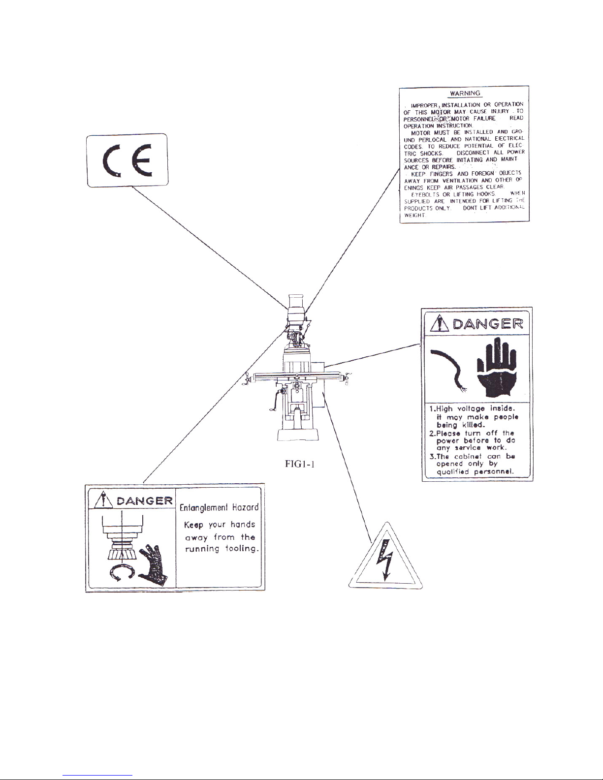
1-2
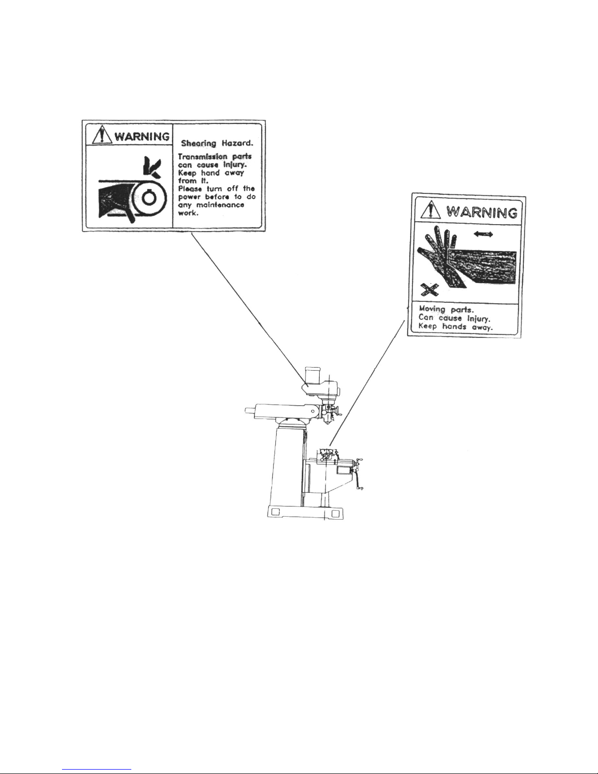
FIG1-2
1-3
1.4 SAFETY DEVICES AND INSPECTION
1-4
2. MACHINE SPECIFICATIONS
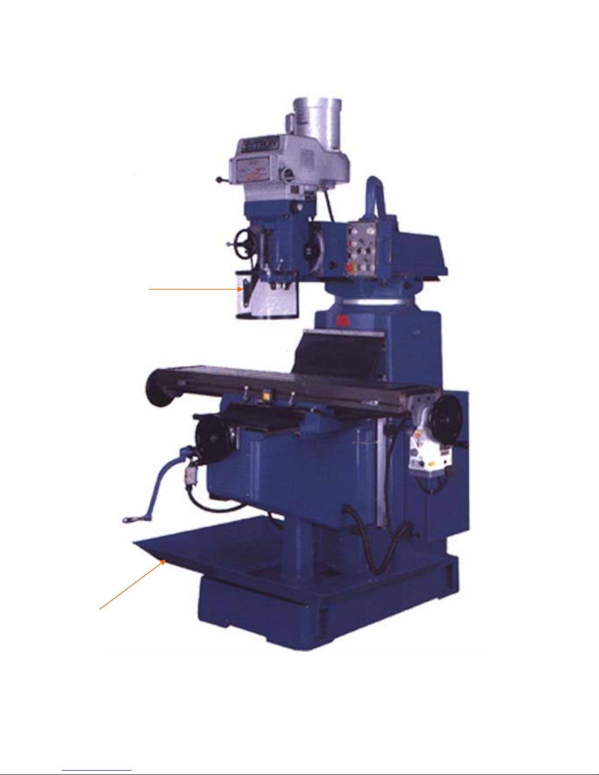
SPINDLE GUARD
(CE OPTION)
CHIP TRAY
FIG1-3

2.1 SPECIFICATION
K5V K5S
WORK TABLE STD. 1320 x 280mm (52”x11”) OPT. 1475 x 280mm (58”x11”)
X AXIS TRAVEL STD. 940mm (37”) OPT. 1094mm (43”)
Y AXIS TRAVEL 395mm (15 - 9/16”)
Z AXIS TRAVEL 500mm (19 - 5/8”)
QUILL DIAMETER Ø105mm (4 .14”)
QUILL TRAVEL 153mm (6”)
QUILL FEED 0.038, 0.076, 0.153mm (0.0015”, 0.003”, 0.006”)
SPINDLE TAPER N.S.T. #40
SPINDLE MOTOR 5HP
SPINDLE SPEED 50Hz L:58-360 H:500-3000(VARIABLE) L:54-270 H:474-2392(4-STEP)
60Hz L:70-425 H:600-3600(VARIABLE) L:65-324 H:569-2807(4-STEP)
A. OVERALL HEIGHT 2310mm (91”)
B. OVERALL DEPTH 1795mm (70 - 5/8”)
C. OVERALL WIDTH 1760mm (69 - 1/4”)
D. MIN. - MAX. DISTANCE 60 - 560mm (2 - 3/8” - 22”)
E. MIN. - MAX. DISTANCE 30 - 488mm (1 - 1/4” - 19 - 1/2”)
F. MIN. - MAX. DISTANCE 162 - 567mm (6 - 3/8” - 23 - 1/4”)
G. MIN. - MAX. DISTANCE 305 - 760mm (12” - 30”)
NET WEIGHT 1630kg 1600kg
PACKED SIZE 165 x 153 x 206cm (1 SET / CRATE) 228 x 153 x 206cm (2 SET / CRATE)
2-1
3. NAMES OF MACHINE PARTS
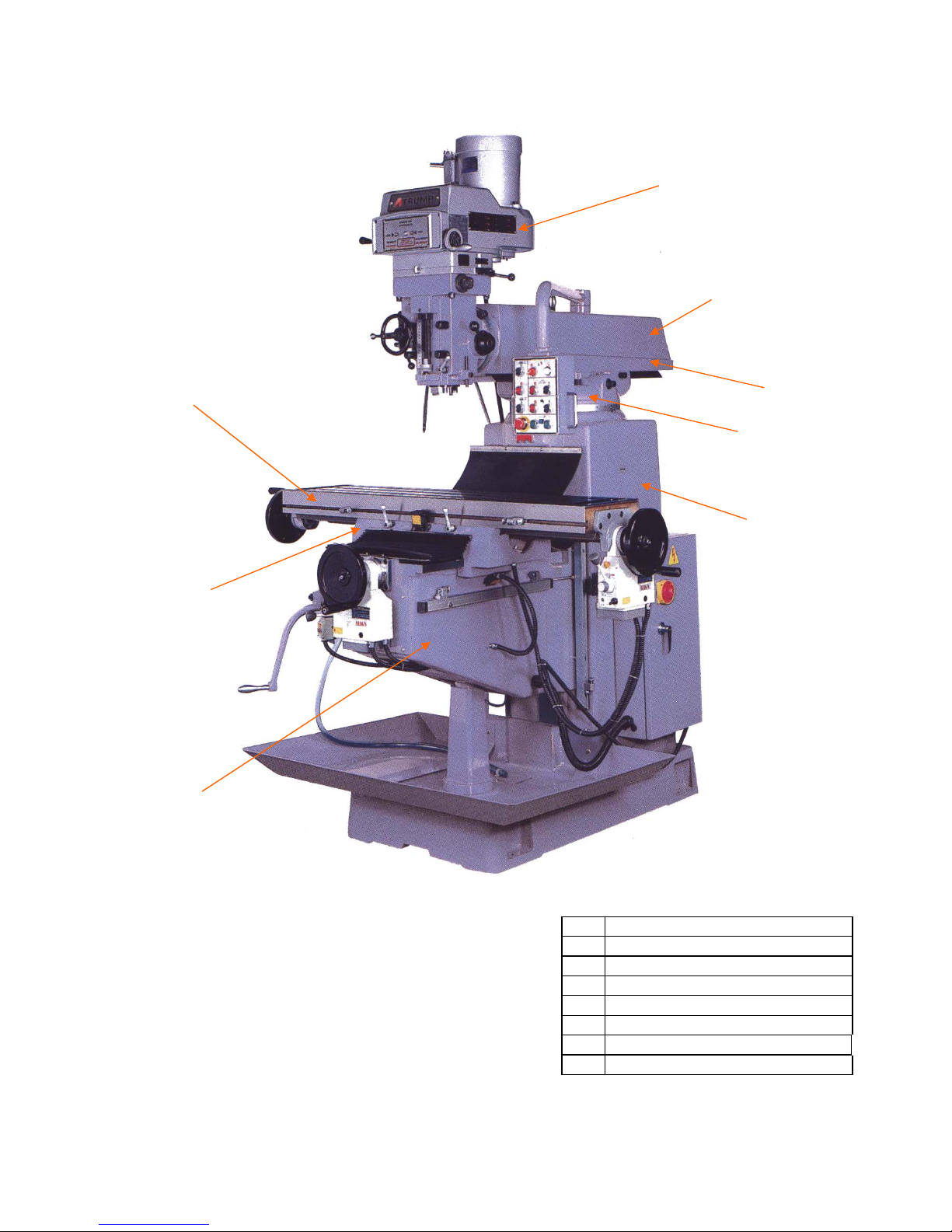
1 Milling head stock
2 RAM
3 Turret
4 Culumn
5 Work table
6 Saddle
7 Knee
8 Operating plate
3-1
3.1 HEADSTOCK
1
4
7
3
8
6
2
5
FIG3-1

FIG3-2
3-2
3.2 MACHINE BODY
(1) COLUMN, TURRET AND RAM
HI-LOW SPEED
SELECTOR
QUILL FEED LEVER
MICROMETER
ADJUSTING NUT
QUILL LOCK
FEED REVERSE
KNOB
HANDLEWHEEL
FEED CONTROL
LEVER
QUILL FEED LEVER
SPEED SELECTOR
HANDLEEWHEEL
FEED REVERSE
KNOB

(2) WORK TABLE, SADDLE AND KNEE
3-3
4. POSITION AND NOISE LEVEL
4.1 OPERATOR POSITION AND NOISE LEVER
RAM
RAM LOCK LEVER
COULUMN
RAMPINION
TURRET
GIBBOLT
FIG3-3
HANDLE WHEEL
SADDLE
KNEE
ELEVATING CRANK
HANDLE WHEEL
SADDLE LOCK
LEVER
WORK TABLE LOCK LEVER
WORK TABLE
FIG3-4

Noise Level:
Less Than 82 dB
At a distance of 1 meter from the sun face of the
machinery and at a height of 1.6 meter from floor.
FIG4-1
4-1
4.2 SPINDLE NOISE DETAIL
Spindle Nose Detail
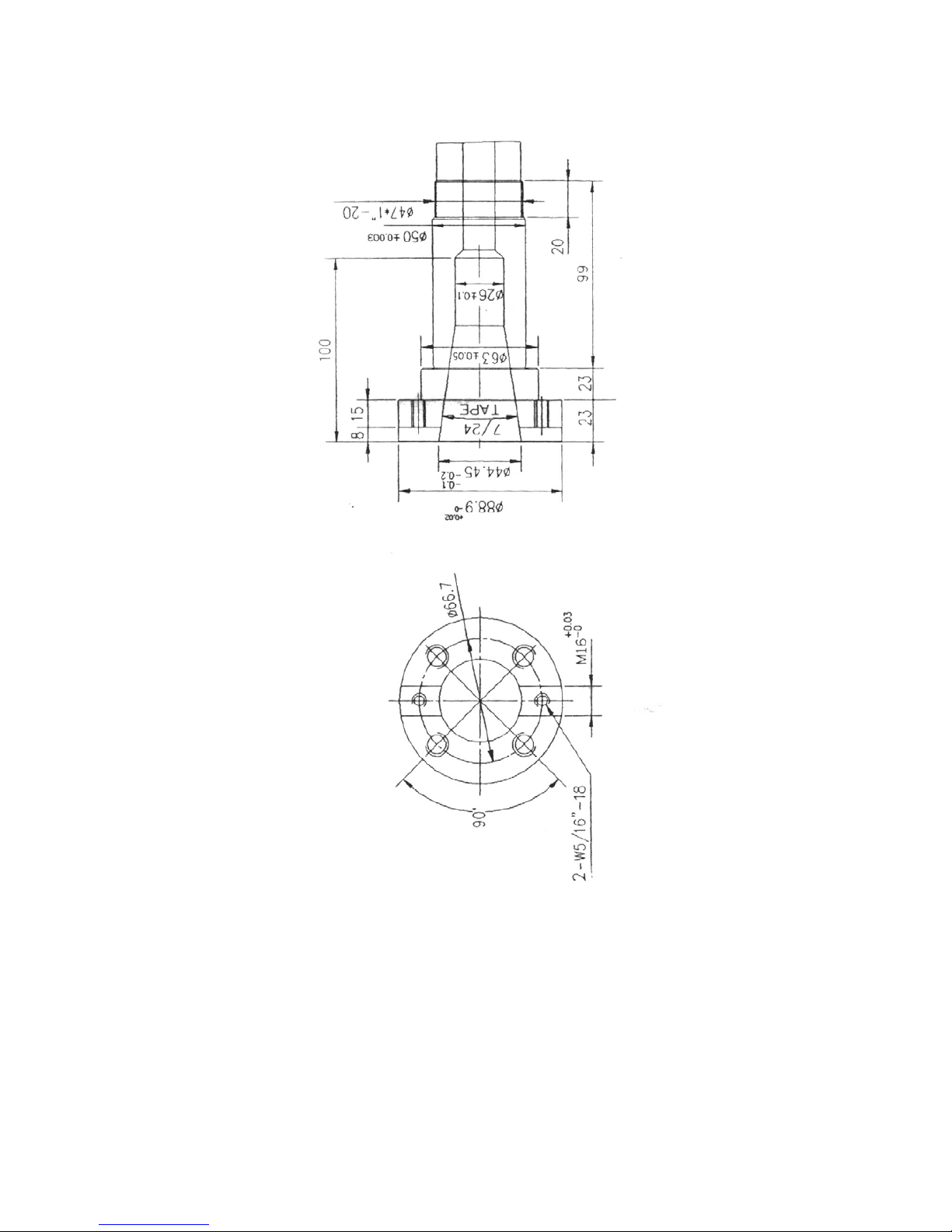
FIG4-2
4-2
5. LUBRICATION
5.1 HEADSTOCK LUBRICATION
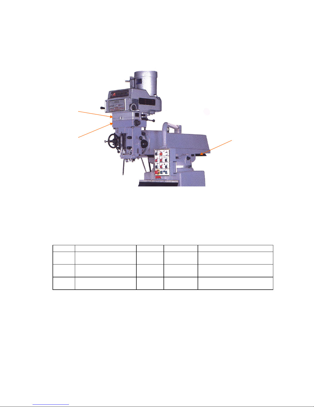
FIG5-1
ITEM LUBRICANTS QTY. TIME POSITION
1 KUO-KUANG R68
ESSO FEBIS K53 FULL TWICE
DAILY COUNTER SHAFT GEAR
WORM GEAR CRADLE
2 COSMO CHASSIS
GREASE NO. 3 FULL ONCE
WEEKLY BULL GEAR BEARING
SLEEVE
3 COSMO CHASSIS
GREASE NO.3 FULL ONCE
WEEKLY HEAD STOCK MATCHING
QUILL HOLES
5-1
5.2 MACHINE TABLE LUBRICATION
3
1
2

FIG5-2
POSITION: LUBRICATION OF WORK TABLE, KNEE, SLIDING SURFACE
AND LEADSCREWS MAY BE EFFECTUATED BY MEANS OF THE
HAND CRANK PUMP ON THE LEFT SIDE OF KNEE.
METHOD: 3 TO 5 TIME DAILY BY PULLING TWICE EACH TIME.
LUBRICANT: KUO KUANG R-68
GULFWAY 52
VACTRA 2
ESSO FBIS K-53
SHELL TONNA 33
5-2
6. INSTRUCTIONS IN OPERATIONS
6.1 HEADSTOCK
SLIDING SURFACE
WORK TABLE
KNEESLIDING SURFACE

6.1.1 SPINDLE SWITCH:
Motor turning is controlled by the push button (vied
the figure in the right). When the high-low speed change
lever (vice FIG6-1,) is placed at the high gear position
and the switch is on CW, the motor turns clockwise. When
the switch is on CCW, the motor turns counterclockwise.
When push the button is on stop, then the spindle is stop.
NOTE : When the high speed change lever is placed at the low
gear position, then, is just on the opposite.
6.1.2 SPINDLE BRAKE:
Before braking, the power source must be switched off,
and waiting until the spindle speed is lower than 200 rpm
before the brake lever is pushed to the left rear or left front
to stop the turning and effectuate the bracking. Push the
brake lever upward and the quill is braked to a full stop for
easy cutter tool change.
NOTE : Be sure that the brake lever in neutral before
starting motor.
6.1.3 Chucking of tooling shank and dismantling
First the spindle must be raised up to its maximum height. The screw of draw bar is right
turn. When the screw is turned clockwise, is for locking of tooling shank, and vice versa.
To take out the tooling shank, the drawbar to allow the tooling shank to separate from
the spindle. Turn the drawbar, until the tooling shank comes off totally.
NOTE : According to spindle braking, brake the spindle to stop and the tooling shank
may easily come off or chuck on.
6.1.4 MANUAL FEED:
The manual feed lever is installed on the right side of head stock . The spindle will
vertically when the lever is turned. There are 12 positio n s t o b e c l o s e n . A n o p e r a t o r c a n
freely take out the lever and install it again at the position deemed proper and fit.
NOTE : In manual feed, the feed control handle (F) must be placed at position (F) as
shown in (FIG6-3.)
6-1
6.1.5 MANUAL MICRO MOTION FEED:
To effectuate the manual micro motion feed, the power feed transmission engagement
crank (J) (FIG6-3) shall be placed at "OUT" position, and feed reverse knob (d), at the
neutral position.
FIG6-1
FIG6-2
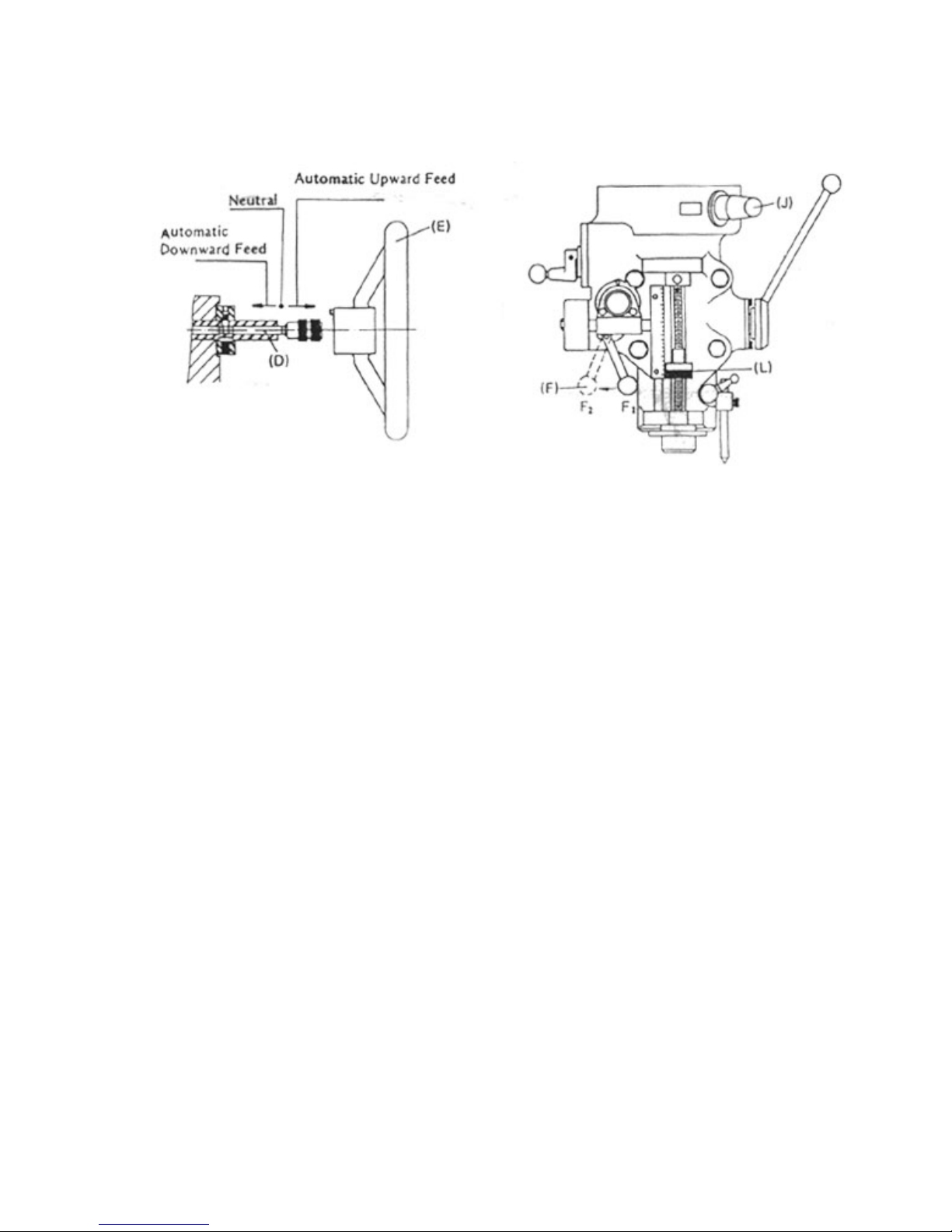
Feed control lever (F) must be pulled from (F1) to (F2). This is to engage the overload
clutch. Turn the feed hand wheel (E) clockwise for quill downward feed, and vice-versa.
6.1.6 AUTOMATIC FEED:
For automatic feeding, please take the following steps (Vide Figure 3,):
a. Loosen the quill lock .
b. Turn the power feed transmission engagement crank.
c. Feed speed is in three stages. H, L and M. selection may be made by quill feed
elector.
d. Pull the feed control lever (F) from (F1) to (F2) position (FIG6-4) to engage the
overload clutch for automatic feed mechanism.
e. When the feed control lever knob (D) pressed inward (FIG6-3), it is for downward
feed, and vice-versa. The middle position is neutral.
f. As shown in (FIG6-4), the working depth may be set by micrometer adjustments
nuts (K) (each graduation is 0.001" or 0.02 mm). When the quill stop block (I)
contacts
the micrometer nut (K), the feed control lever (F) may simply jump from (F2) back to
(F1) position owing to the connecting motion between the feed trip lever and feed trip
plunger. This will disengage the overload clutch and stop the spindle feed.
NOTE : 1. Maximum drilling capacity in automatic feed is 3/8" or10 mm.
2. The power feed transmission engagement crank (I)
6-2
(Figure 3) shall be placed at "out" position when the
automatic feed is not in operation. do not move the
power feed transmission engagement crank when the
spindle is in revolution.
FIG6-3

6.1.7 SPEED CHANGE OF SPINDLE
(1) Speed change
By means of the variation of one set of slicking belt pulley and counter 1 shaft gear
(high or low speed), the spindle revolution speed is changed accordingly.
Change of high and low speeds:
The speed change may be effectuated by the chosen high and low speed lever (FIG6-5
(J) ). When (J) is engaged in the right front, it is for the high speed and the spindle
rotate as high as 500 or 3,000 rpm. The neutral lever position is in the right down.
NOTE: a. The spindle must be motionless completely during the speed change.
b. To shift the high speed into the low one, the spindle must be slightly
turned
to make it easier for the back row gear to engage.
c. To shift the low speed into the high one, use the brake lever so as to put a
stop to the spindle clutch. Then turn the spindle slightly so that the clutch
may be engaged feasibly. A ''click" sound of engagement may be sensed at
this moment.
d. The direction of low speed rotation is opposite to that of the high speed. By
the reversing switch, the direction may changed to that high speed
revolution.
Speed change hand wheel:
Step less speed variation between high and low speeds may be controlled by means of
the turning hand wheel (FIG6-5(G) ) when it is turned clockwise, it is for higher
speed, and vice-versa.
NOTE: a. Do not change the speed when the spindle stands still.
6-3
b. Avoid to use it when the speed is in excess of 3,000 rpm.
c. In the process of speed change from high speed to low
speed, and vice- versa, do not change the speed rapidly
FIG6-4

to safeguard the speed rapidly to safeguard theservice
life of the internal mechanism.
d. It takes roughly 10 to 15 minutes to change from low
speed to the high one, and viceversa.
6-4
6.1.8 HEADSTOCK TILTING
Cross tilting (FIG6-6:)
Loosen evenly the four lock nuts and turn the worm shaft (S) until the desired angle is
G
J
This manual suits for next models
1
Table of contents
Other Atrump Power Tools manuals


