ATS Chill V Series Operating and maintenance manual

ATS-Chill V Series
Re-Circulating Chiller
Instructional Manual
89-27 Access Road, Norwood, MA 02062 | T: 781.769. 2800 F: 781.769.9979 | www.qats.com
ATS-Chill V Series

Warranty Agreement
Limited Warranty
Advanced Thermal Solutions, Inc. (hereinafter “ATS”) warrants that: (1) the ATS-Chill V
Series chillers will perform in accordance with the written materials for a period of ninety
(90) days from the date of purchase; and (2) Software will be free from defects and errors
in materials and workmanship, and covered for a period of ninety (90) days from the date
of purchase if utilized under normal use and service. Any implied warranties on the Software
are limited to ninety (90) days.
Customer Remedies
ATS and all its suppliers’ entire liability and the consumer’s exclusive remedy shall be at ATS’s
option, either for the return of the price paid or the repair and replacement of the Software or
Hardware that does not meet the limited warranty and which is returned to ATS. The limited
warranty is deemed to be null if the failure of the Software and accompanying material results
from an accident, abuse, and/or misapplications. Any replacement of the Software and
accompanying material will be warranted for the remainder of the original warranty period or thirty
(30) days, whichever is longer.
ATS and its suppliers disclaim any and all other warranties, whether expressed or implied,
including but not limited to implied warranties of merchant ability and tness for a particular
purpose, with regard to the Software and accompanying written and Hardware material. This
limited warranty provides you with specic legal rights; however, you may have other rights which
would vary from state to state.
In no event shall ATS or its suppliers be liable for any damages whatsoever arising out of the use
of or inability to use this product, even if ATS has been advised of the possibility of such damages.
However, some states do not allow the exclusion or limitation of liability for incidental damages,
hence this limitation may not apply.
NO LIABILITY FOR CONSEQUENTIAL DAMAGES. In no event shall ATS or its suppliers be
liable for any damages whatsoever (including, without limitation, damages for loss of business
prots, business interruption, loss of business information, or other pecuniary) loss arising from
the use of or inability to use this ATS product, even if ATS has been advised of the possibility of
such damages.
COPYRIGHT
The ATS-Chill V Series and its operating software is patent pending and proprietary to Advanced
Thermal Solutions, Inc.
DISCLAIMER
While every effort is made to ensure accuracy, Advanced Thermal Solutions, Inc, cannot be held
responsible for errors or omissions in this Manual. Furthermore, it reserves the right to revise this
document and make changes without notice.

Contents
1. Safety Notes 3
2. Unpacking 3
3. Equipment Description 3
4. Brief Instructions 4
5. Operating Panel 5
6. Technical Data 8
7. Maintenance 8
Table of Contents

Section 1: Safety Notes
1. Safety notes
• Transport the equipment with care
• The unit must NEVER be overturned nor put upside down
• The equipment and its internal parts can be damaged:
- by dropping
- by shock
• The equipment should only be operated by properly instructed personnel
• Never operate the equipment without bath liquid
• Do not start up the equipment if:
- it is damaged or leaking
- the supply cable is damaged
• Switch off the equipment and pull out the mains plug for:
- servicing or repair
- before moving the equipment
• Drain the bath before moving the equipment
• Have the equipment serviced or repaired only by properly qualied personnel
Other ATS Liquid Cooling Products:
• Flow Meters
• Leak Detectors
• Cold Plates
• Heat Exchangers
For these products and the entire ATS product line visit www.qats.com.
Before you operate the equipment please carefully read all the instructions and safety notes.
If you have any questions please call 781-769-2800. Follow the instructions on setting up,
operation etc. This is the only way to exclude incorrect operation
of the equipment and to ensure full warranty protection
Chill V Series

Figure 1 Water Outlets
Figure 2 Water Tank
Container
Section 2: Unpacking
The ATS-Chill V Series chillers are packed carefully to prevent
damage in transport. After unpacking, rst check the equipment and
accessories for possible transport damage. If, unexpectedly, the
equipment is noticeably damaged, it is essential to notify the forwarding
agent or the postal authorities so an inspection can take place. Do not
start operations with damaged instruments. The unit may NEVER
be overturned nor put upside down
Section 3: Equipment description
Materials
All components in contact with the thermostating liquid are made
specically from materials suitable for the recommended liquids and
temperature, such as rust free, stainless steel, copper, brass, NBR
and/or plastics.
Refrigeration unit
The refrigeration unit consists essentially of a fully sealed
compressor. The thermostating liquid is cooled through a heat
exchanger located inside the bath. Heat of condensation and motor
heat are dissipated on air-cooled units through a fan-cooled ribbed
condenser.
The refrigeration unit is protected against overpressure and
compressor overload. With insufcient ventilation of the condenser
(e.g. dirt deposits) the equipment is switched off.
Control unit
The control unit is provided with an LED display which indicates
the measurements and settings as well as the operational status
functionality. The set-point and other control settings are selected
using two or three keys.
A Pt 100 temperature probe senses the outow temperature inside
the bath. The measurement is processed by a high-resolution AD
converter. Further processing involves a special control algorithm to
operate the heating triac (with reduced reaction on the main supply),
the automatic compressor control, and the cooling control which
operates with low-noise solenoid valves. The proportional cooling
principle permits control in the cooling range without any energy
wasting counter-heat.
Chill V Series

Chill V Series
Section 4: Brief instructions
4.1 Assembly and setting up
It is advisable to set up the equipment so that the
control unit is towards the front and that the ventilation
for the refrigeration unit, especially on equipment with
an air-cooled condenser, (ventilation grille in lower part)
is not impeded. Ensure a minimum spacing of 0.5m
between ventilation grille and wall.
4.2 Filling and connection of external circuit
• Fill the equipment with the appropriate circulating liquid to suit the operating
temp. It should be lled with pure water or a water-glycol mixture (min. 70:30%).
• When using water as the heat carrier for the CHILL-V ensure that there are
no operating temperatures below 5°C in the outow.
• To assist in venting the pump, the pressure connection should be left open
when the equipment is lled for the rst time, otherwise there may be permanent
damage to the pump.
• Remove the plug on the ller opening at the upside. A funnel can be used for lling.
• When starting up for the rst time, ll the bath as full as possible, up to the max. level.
• After lling up an external circuit, further liquid may have to be added.
• Connect the pump connections at the back of the equipment to the external circuit. The
external circuit must be pressure-tight.
• Switch off the equipment before releasing the hose connections; the hose couplings are
not self-sealing.
• Always ensure maximum ow cross-section in the external circuit (nipples,
tubing, external apparatus). This results in increased ow rate and therefore
better thermostating.
• The equipment is designed for operation with non-ammable liquids.
Flammable liquids must not be used at temperatures higher than 25°C below
the ame point

Chill V Series
Section 4: Brief instructions (con’t)
4.3 Connection to the supply
Connect the equipment only to a supply socket with protective earth contact.
Check the details on the rating label against the supply voltage. No warranty applies
when the equipment is connected to the wrong supply.
4.4 Emptying
Place a container underneath the drain cock on the back of the equipment.
Switch off the equipment. Observe the appropriate regulation when disposing
of used circulating liquid. Close the drain cock.

5. Operating Panel
Key Functions
POWER
Power key
COOL Cooling Key
PUMP Circulating Key
Setup key, for accessing parameter
table and conrming change
Data shift key, also for
activating auto turning
Date increase key
Data decrease key
Display window
PV Process Value Display: Displays PV or code of a parameter
SV Setting Value Display: Displays SV, alarming code or value of a parameter
LED indicator
OUT Output Lamp
AUTO Auto Optimize (Auto-tuning )
OVER Over temperature alarm
LEVEL
Low Level alarm (Option )
Operation Description
Basal display status: When powered on, the upper display window of the instrument
shows the process value (PV), and the lower window shows the set-point (SV). This status
is called basal display status. When the input signal is out of the measurable range (for
example, the RTD circuit is broken, or input specication is set wrong), the upper display
window will alternately display “orAL” and the high limit or the low limit of PV, and the
instrument will automatically stop output.
Chill V Series

Chill V Series
5. Operating Panel (con’t)
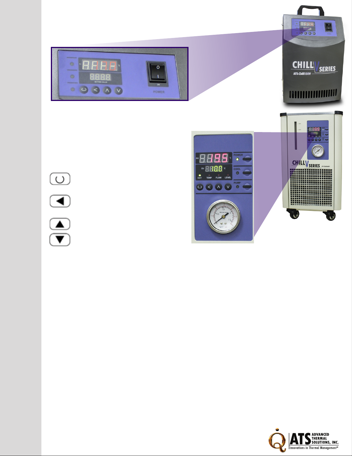
Set Value Setting:
In basal display status, we can set the set-point (SV) by pressing or .
Press to decrease the value, to increase the value, and to move
to the digit expected to modify. Keep pressing or , to speed up the decreasing
or increasing of the value.
Parameter Setting:
In basal display status, press and hold for about two (2) seconds in order
to access Field Parameter Table. Pressing can go to the next parameter;
pressing or can modify a parameter. The instrument will escape
automatically from the parameter table if no key is pressed within 30 seconds.
Intelligence control and auto tuning
When the “At” control method is chosen, the control parameters can be obtained by
running auto-tuning. At the rst time of running auto-tuning, in basic display status, “At”
will ash in the lower display window and the instrument executes on-off control. After
two (2) to three (3) cycles of on-off action, the instrument will obtain the values of PID
control parameters. If you want to escape from auto tuning status, press for about
two (2) seconds until the “At” ash stops. Depending on the system, the time of auto tuning
can be several seconds to several hours. After the auto tuning nishes, the parameter “At”
automatically changes to “OFF”. If the user wants to run auto tuning again, set the setting
parameter from “At” to “on”.
Note 1: Before running auto-tuning, the set-point should be set to an often-used value
or middle value rst, and then start auto-tuning. Generally, for applications with heating
time of 10~80% satisfying auto-tuning results can be obtained. If the heating time is not
in the range of 10~80%, the auto-tuning will continually run, searching for satisfying
result. Raising the set-point for heating time less than 10% or decreasing the set-point
for heating time greater than 80% can improve auto-tuning result.
Note 2: Don’t modify the set-point during auto-tuning. It may affect the precision of auto-tuning.
Note 3: The temperature uctuation caused by interference may affect the precision of
auto-tuning. Besides checking the wiring, increasing the parameter FILt (input digital lter)
can also reduce interference.
Note 4: After auto-tuning nishes, the temperature rising typically has a little over-shoot
(about 1~3°C). The transducer is often placed between the heater and heated material,
and a little over-shoot can shorten the time of rising to set-point and save power. (Generally,
the temperature of the transducer can be raised quickerthan that of the heated material.)

6. Technical Data
Specications for Chill-V
Model Chill150V Chill300V Chill600V Chill1000V
Temperature range
@25°C 5~40°C 5~35°C 5~35°C 5~35°C
Temperature Stability ±0.1°C ±0.1°C ±0.1°C ±0.1°C
Cooling
Capacity@20°C 150W 300W 600W 1000W
Pump pressure 0.4bar 0.6/4bar 4bar 4bar
Pump Flow Rate 7-10 L/min 15 L/min 10L/min 10 L/min
Working mode Continuous Continuous Continuous Continuous
Filling Port mm Ø25 Ø25 Ø25 Ø25
Reservoir Capacity 1.0 L 4.5 L 8 L 8 L
Dimensions
(W x D x H)
230 x 260 x 380mm
(9.06 x 10.24 x 14.96”)
235 × 475 × 490mm
(9.25 x 10.24 x 19.29")
325 x 620 × 550
(12.8 x 24.4 x 21.65")
325 x 620 × 550
(12.8 x 24.4 x 21.65”)
Power Volts Hz Amps AC220V, 50Hz, 5A AC220V, 50Hz, 10A AC220V, 50Hz, 10A AC220V, 50Hz, 10A
Shipping Weight (kg) 10 23 32 40
Chill V Series

Chill V Series
7. Maintenance
7.1 Cleaning
• Before cleaning the equipment,
remove the main plug.
• The unit can be cleaned with water
with the addition of a few drops of a
detergent (washing-up liquid), using a
moist cloth.
• Water must not enter the control unit
• The user is responsible for carrying out an appropriate detoxication of any
dangerous material which has been spilled on or in the unit. This applies in
particular when the unit is passed on to someone else for operation, repair,
storage etc.
7.2 Maintenance of the refrigeration unit
• The refrigeration unit operates largely
maintenance-free. If the unit is being operated
in a dusty atmosphere the condenser of the
refrigerator has to be cleaned at intervals of 4 to
6 months or more frequently. This is best done
by blowing compressed air or nitrogen into the
ventilation openings for a few minutes
• It may be useful to unscrew the grill. This can
be done in a most suitable way by screwing off
the ventilation grid, then cleaning the condenser
with a vacuum cleaner (using the brush-top).
7.3 Repair and disposal instructions
• The refrigeration unit is lled with refrigerant.
Repair and disposal must only be carried out by a qualied refrigeration technician.
• Before you return the equipment for servicing it is advisable to contact our
Technical Service department.
• If the equipment has to be returned to the factory, please ensure that it is
carefully and properly packed. We accept no responsibility for damage
due to unsatisfactory packing.

www.qats.com
Advanced Thermal Solutions, Inc
Advanced Thermal Solutions is a leading engineering and
manufacturing company supplying complete thermal and mechanical
packaging solutions, from analysis and testing to nal production. ATS
is world renowned for its portfolio of more than 5,000 high performance
heat sinks, research-quality test equipment’s, and leading-edge R&D,
specically tailored to the telecom, LED and computing industries. In
addition, ATS provides thermal design consulting services and training
for the electronics cooling industry. For more information about
Advanced Thermal Solutions, please visit www.qats.com.
For further technical information, please contact
Advanced Thermal Solutions, Inc. at 781.769.9979
Advanced Thermal Solutions, Inc
89-27 Access Road,
Norwood, MA 02062
phone: 718.769.2800
This manual suits for next models
4
Table of contents
Other ATS Chiller manuals
Popular Chiller manuals by other brands

teca
teca TLC-702 Product information packet

Trane
Trane CXAJ065 Maintenance manual

Carrier
Carrier CNPVU Series installation instructions

Advanced Thermoelectric
Advanced Thermoelectric ElectraCOOL L-A 550 user manual

McQuay
McQuay Seasonpak PAB Series Installation and maintenance data

LEGRAND
LEGRAND MINKELS CW40 user manual