ATS US-2000 V5 User manual

FELINS.COM
ATS US-2000 WITH V5
Service Manual
Felins’ US-based banding professionals provide full service
and support for ATS banding systems.
PARTS & SERVICE INQUIRIES:
(800) 336-3220
Milwaukee, WI

Dokument: Serviceanleitung_US2000V5_EN_V0.0.docx
Issued: 22.02.2016
Author: Philipp Meyer
SERVICE MANUAL
US
-
2000
V5

US
-
2000
(
DCP 2000 V
V
5)
SERVICE MANUAL
C
E
Fertigstellung: 02.16
US
-
2000
gg
Serviceanleitung_US2000V5_EN_V0.0.docx
Page 2 of 23
BEDIENUNGSANLEITUNG Table of contents US-2000 (DCP 2000 V5)
1. Maintenance ................................................................................................... 4
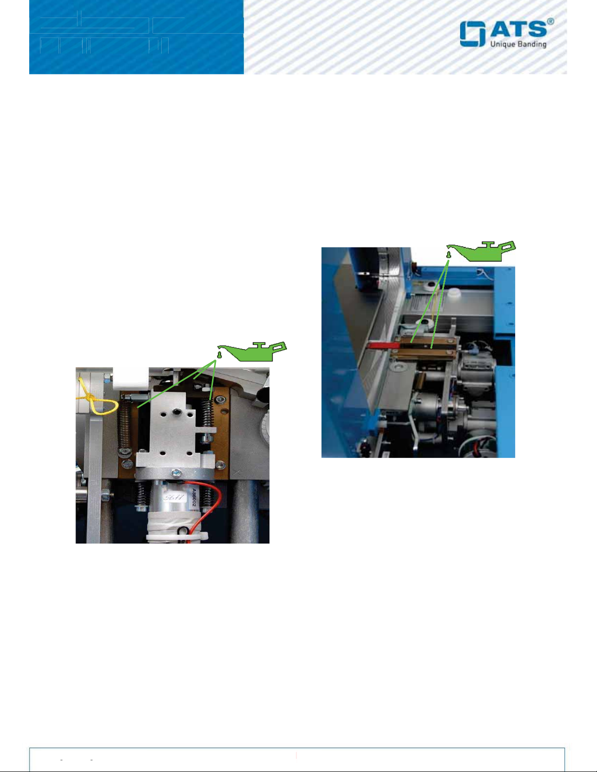
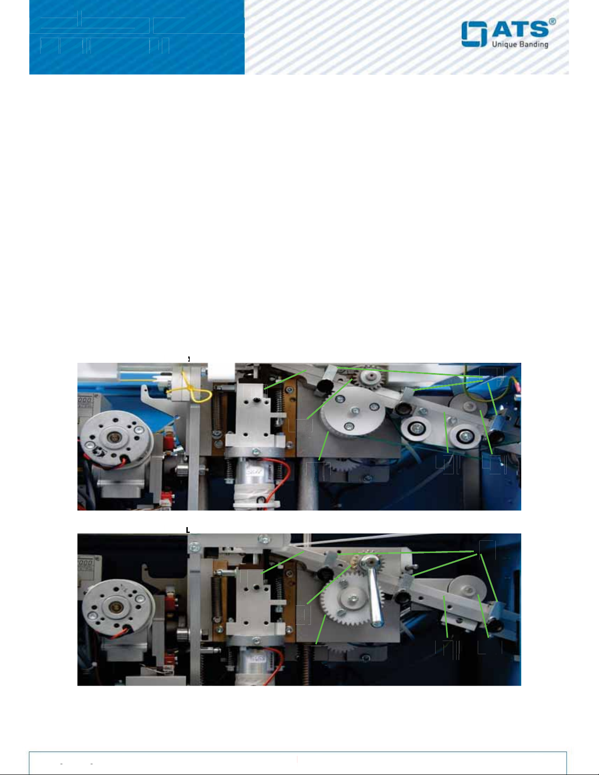
1.1. Monthly maintenance ............................................................................................. 4
1.2. Cleaning of the band channel ................................................................................ 5
2. Mechanical settings ....................................................................................... 6
2.1. Rubber roller ............................................................................................................... 6
2.1.1. Adjusting the rubber roller pressure .....................................................................6
2.1.2. Replacing the rubber roller .................................................................................. 6
2.2. Encoder ................................................................................................................... 7
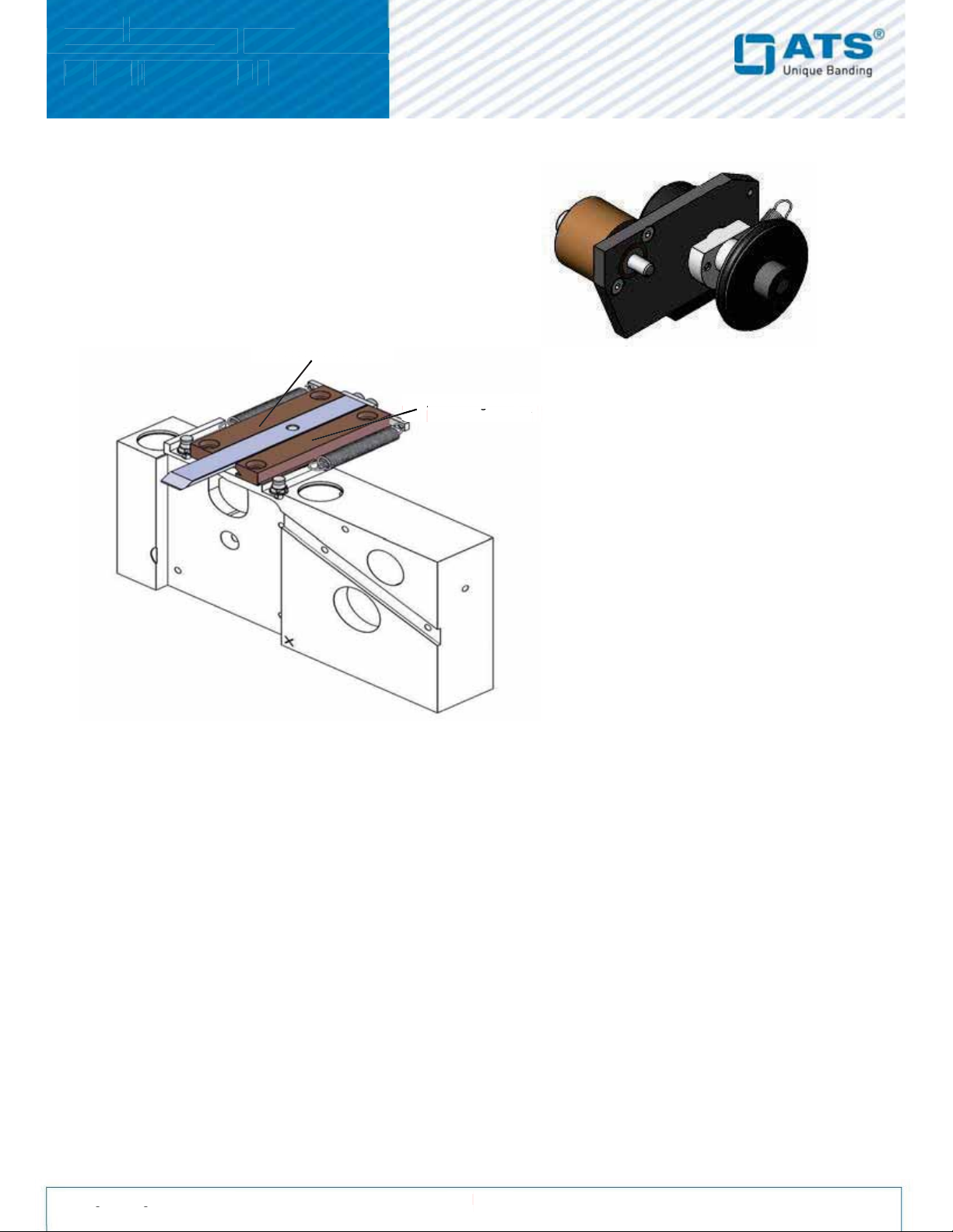
2.3. Anvil ........................................................................................................................ 7
2.3.1. Adjusting play of the Anvil .................................................................................. 7
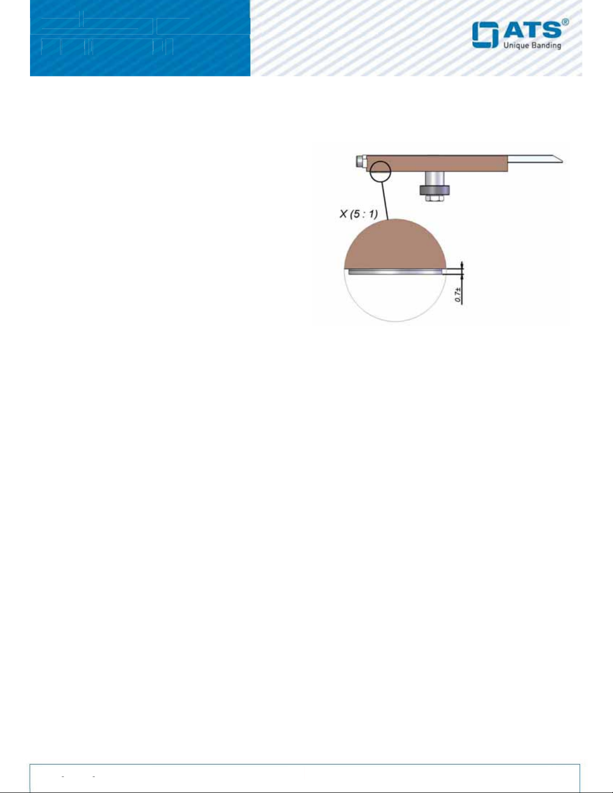
2.3.2. Adjustment for a parallel weld ............................................................................ 8
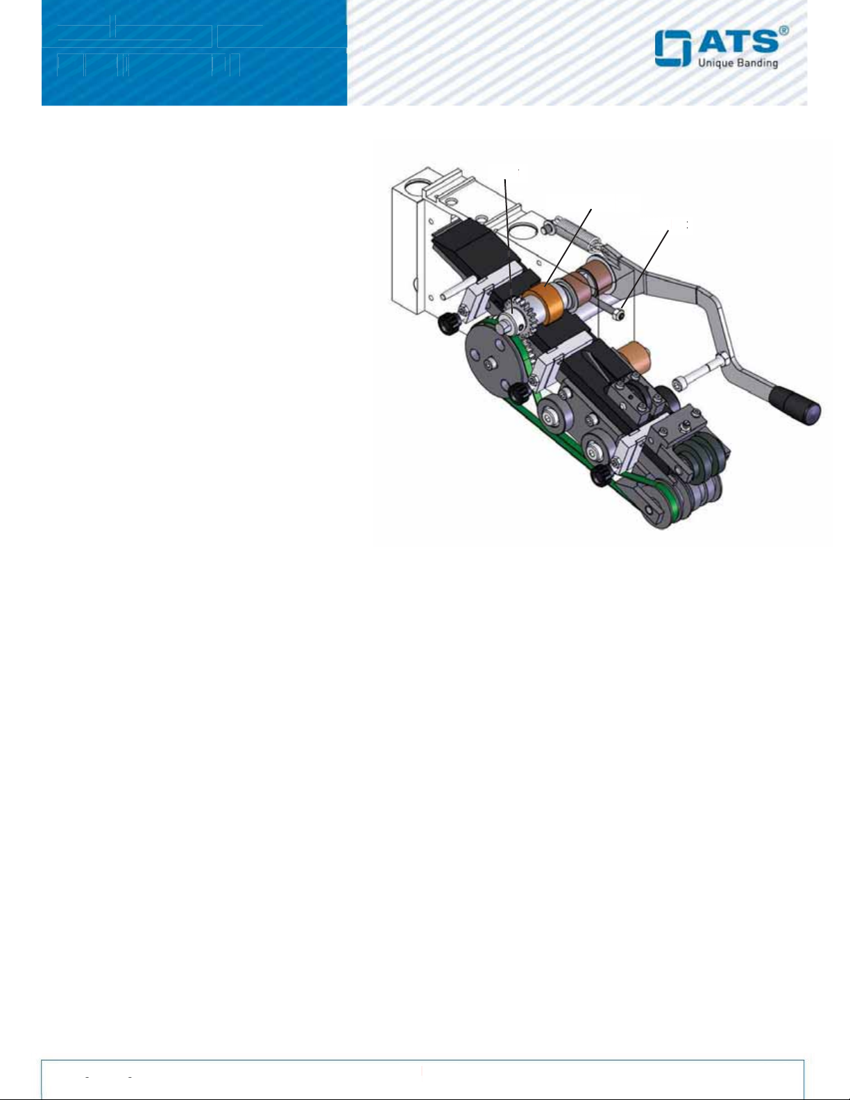
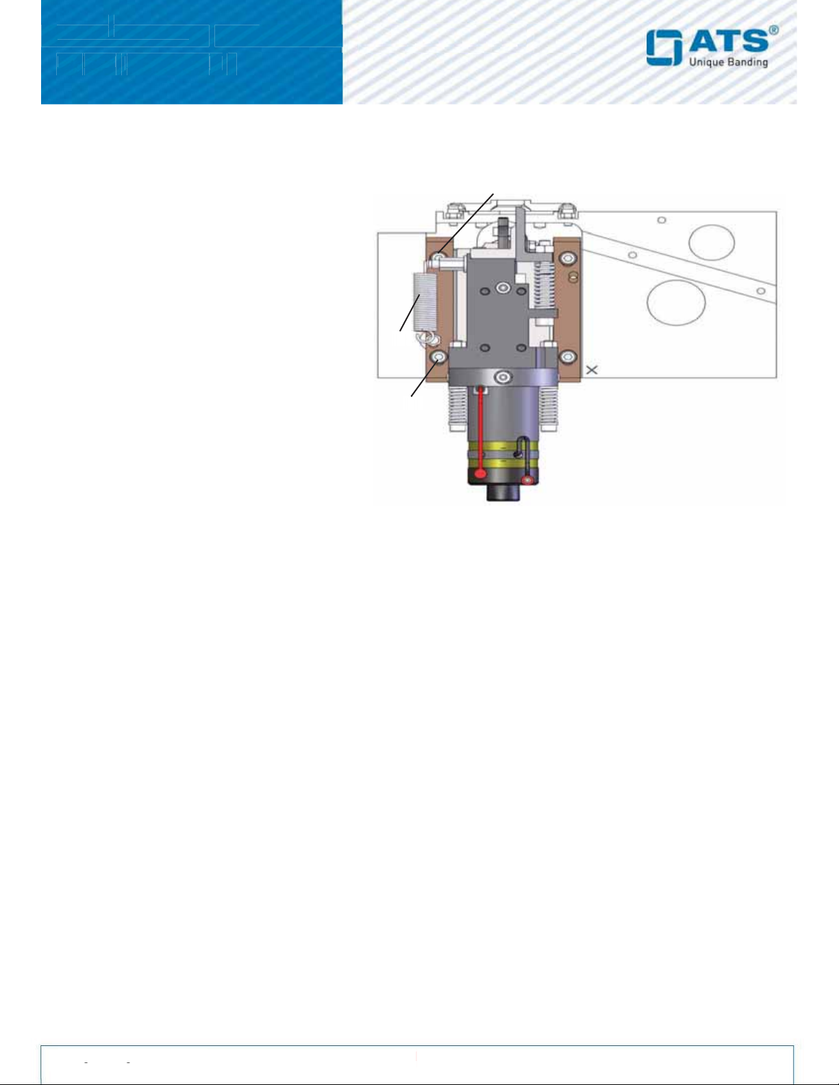
2.4. Sonotrode slide .................................................................................................... 8
2.4.1. Removing the sonotrode slide ............................................................................ 9
2.4.2. Mounting the sonotrode slide ............................................................................. 9
2.5. Sonotrode and generator ....................................................................................9
2.5.1. Removing the sonotrode ................................................................................... 10
2.5.2. Mounting the new sonotrode ..............................................................................10
2.5.3. Adjusting the generator ..................................................................................... 11
2.6. Cutter ...................................................................................................................12
2.6.1. Replacing the cutter ..........................................................................................12
2.6.2. Maintenance of the cutter ..................................................................................12
2.7. Aggregat Motor M1 ..............................................................................................13
2.7.1. Replacing the aggregatmotor ............................................................................13
2.7.2. M1 gear ratio .....................................................................................................13
2.8. Band Motor M2 .....................................................................................................14
2.8.1. Replacing the bandmotor ..................................................................................14
2.8.2. M2 gear ratio .....................................................................................................14
2.9. Arch Motor M3 .....................................................................................................15
2.9.1. Removing the arch-motor .................................................................................15
2.9.2. Mounting the new arch-motor ...........................................................................15
2.9.3. M3 gear ratio .......................................................................................................15
2.10. Driving shaft .......................................................................................................16
2.10.1. Removing the driving shaft ................................................................................16
2.10.2. Adjusting the driving shaft (clutch/ brake) ..........................................................17
2.11. Arch-string (yellow cord) ...................................................................................18
2.11.1. Adjusting the arch-string....................................................................................18
2.11.2. Loop Cup Adjustment.............................................................................................................18
2.11.3. Ejection Pin Adjustment.....................................................................................19

US
-
2000
(
DCP 2000 V
V
5)
SERVICE MANUAL
C
E
Fertigstellung: 02.16
US
-
2000
gg
Serviceanleitung_US2000V5_EN_V0.0.docx
Page 3 of 23
Table of Contents
3. Machine Sensors..................................................................................................19
3.1.1 Photo Sensors............................................................................................................19
3.1.2 Tape End Sensor........................................................................................................20
3.1.3 0 Point Sensor............................................................................................................20
3.1.5 S7/S8 Sensors............................................................................................................20
4. Print mark (option) ..............................................................................................21
5. X50 Connection....................................................................................................22
4.1. Signals up - / downstream…………………….......................................................23

US
-
2000
(
DCP 2000 V
V
5)
SERVICE MANUAL
C
E
Fertigstellung: 02.16
US
-
2000
gg
Serviceanleitung_US2000V5_EN_V0.0.docx
Page 4 of 23
Maintenance
1. Maintenance
Maintenance work must be performed exclusively by authorised personnel. The machine must always be turned
off and disconnected from the power grid prior to that!
The indicated maintenance interval refers to single shift operation in a normal environment.
1.1. Monthly maintenance
Procedure:
1. Fold down the front planel.
2. Remove product guides
3. Remove rear table
4. Clean machine using compressed air or a vacuum cleaner.
5. Blow out the arch using compressed air.
6. One drop of oil each into the left and the right lead of the Anvil.
7. One drop of oil each into the left and the right lead of the sonotrode.
8. One drop of oil into the guide slot for the knife.
Important: Solvents or alcohol must never be used to clean the plastic arch

US
-
2000
(
DCP 2000 V
V
5)
SERVICE MANUAL
C
E
Fertigstellung: 02.16
US
-
2000
gg
Serviceanleitung_US2000V5_EN_V0.0.docx
Page 5 of 23
Maintenance
1.2. Cleaning of the band channel
Procedure:
1. Remove the band from the arch by resetting the machine.
2. Operate the release lever and pull the start of the band out of the band channel.
3. Fold down the front panel.
4. Remove all three band channel quick release clamps (A).
5. Carefully move the right feed track cover (B) to the right while lifting the rotary encoder (C).
6. Carefully pull the left feed track cover (D) forward.
7. Carry out the cleaning: Band drive roll aluminum (E), rubber feed roller (F), feed track and feed track
covers
8. Assemble in reverse order.
9. Thread the band according to instructions.
Important: Band channel incl. lid, rotary encoder, aluminum and rubber feed roller must in no case be cleaned using abrasive
cleaning agents or other abrasive agents (e.g. file).
Important: When assembling the band channel quick release clamps (A) make sure that the knurled screws are at the bottom,
as shown in the picture.
Band channel of US
-
AD Arch machine
A
A
2000
E
F
D
B
A
A
A
C
Band channel of US
-
LD Loop machine
L
L
2000
A
A
A
D
E
F
B
C

Mechanical settings
US
-
2000
(
DCP 2000 V
V
5)
SERVICE MANUAL
C
E
Fertigstellung: 02.16
US
-
2000
g
g
Serviceanleitung_US2000V5_EN_V0.0.docx
Page 6 of 23
2. Mechanical settings
2.1. Rubber roller
When the tape is inserted and drawn
back it is held between the rubber roller
and the tape drive roller. The required
clamping tension is adjusted with the
set-screw, pushing on the excentric
shaft. The rubber roller can be raised, by
pushing down the release lever in order
to ease off the tension when loosing up
a tape jam (or inserting the tape on loop
machines).
2.1.1. Adjusting the rubber
roller pressure
1. The rubber roller needs to be adjusted
without any band between the rubber
roller and feed roller > remove all band
from the track.
2. Make sure the rubber roller and feed
roller are clean
3. Loosen up the lock-nut on the set screw
on the right side of the aggregate.
4. Turn the set-screw counter-clockwise until it does not touch the excentric shaft anymore.
5. Turn the set-screw clockwise until it touches the excentric shaft of the rubber roller.
6. Turn the set-screw clockwise by another ¼ turn.
7. Lock the lock-nut.
Note: The rubber roller should slightly touch the feed-roll. The rubber-roller needs to be replaced, as soon as it
has reached a diameter of Ø 29.5 mm.
2.1.2. Replacing the rubber roller
1. Remove collar and ring from the excentric shaft.
2. Remove the left and right track cover.
3. Remove the support bar (supporting the front table plate).
4. Remove the tension from the rubber roller, by pushing down the release lever.
5. Pull the rubber roller off the excentric shaft.
6. Mount the new roller in reverse order.
7. Adjust the pressure of the new rubber roller.
8. Note teh special washer between the collar and the rubber feed roller.
Lock
-
nut
t
collar
r
Min.
Ø 29.5
mm

Mechanical settings
US
-
2000
(
DCP 2000 V
V
5)
SERVICE MANUAL
C
E
Fertigstellung: 02.16
US
-
2000
g
g
Serviceanleitung_US2000V5_EN_V0.0.docx
Page 7 of 23
2.2. Encoder
The encoder measures the band during the infeed and drawback
of the band.
To ensure a consistant over lap, the o-ring of the encoder should
get replaced once a year.
The tension spring on the encoder applies pressure to the
encoder wheel, so it does not jump on the band. The spring
needs to be replaced if stretched.
2.3. Anvil
The anvil provides counter pressure for the clamp when the tape is
pulled back and also for the Sonotrode during the welding process.
The anvil moves horizontally to release the tape after welding.
2.3.1. Adjusting play of the Anvil
In order to have a good welding, the play of the
anvil should be kept at a minimum when it is in the
front position.
1. To check the play, the anvil must be in the front position and not
clamped. >infeed position of the servicemode
2. The left guide is the reference and must be pushed all the way to the
left (no gap between the aggregate and bronze guide) then
tightened.
3. Adjust the play of the anvil with the right guide to a minimum but
make sure that it does not get pinched as the anvil moves in the
front position.
4. Check the play again after tightening all four screws. Even with only
one spring it should pull the anvil back in the front position.
5. Reattach both springs. Make sure that the springs are rotated one-
half turn to prevent them from getting stuck on the underside of the
rear table.
Note: Always use the two shorter screws on the front side of the anvil.
Left bronze guide
right bronze guide
g
g
right
g
ht
(
t
bronze
guide
t
t
g
g
to adjust the play
y
)

Mechanical settings
US
-
2000
(
DCP 2000 V
V
5)
SERVICE MANUAL
C
E
Fertigstellung: 02.16
US
-
2000
g
g
Serviceanleitung_US2000V5_EN_V0.0.docx
Page 8 of 23
2.3.2. Adjustment for a parallel weld
To achieve an optimum (even) seal, the angle of the anvil can be adjusted with shims underneath the back side of
the anvil-guides.
1. Bring the machine with the service mode in the
infeed position (anvil in the front but not clamped).
2. Remove all 4 screws from the bronze guides
(Please note, that there are usually already shims
underneath the guides).
3. Depending on what side you need to improve the
sealing, remove or add shims on the back side of
the guides (Note: only use precise grounded
shims (ATS-Order No: BN1976 6x12x0.5/
BN1976 6x12x0.2).
4. Make sure you add or remove the same amount of
shims on the left and the right guide.
5. Mount the guides with all 4 screws but do not
tighten them yet.
6. Put the anvil all the way back between the guides.
7. Adjust the play of the anvil by following steps of
section 2.3.1.
8. Check the sealing again for a parallel welding
More shims in the back = more pressure
Less Shims = less pressure
Note: Only add shims on the back side of the anvil as shown in the picture. Shims in the front of the anvil could
lead to an incomplete cutting of the band.
2.4. Sonotrode slide
The sonotrode slide moves the sonotrode, knife and clamp along the vertical axis and has following
functions:
•Clamps the band durring draw back between the anvil and clamp.
•Presses the sonotrode against the anvil during the welding process.
•Cuts the band.

Mechanical settings
US
-
2000
(
DCP 2000 V
V
5)
SERVICE MANUAL
C
E
Fertigstellung: 02.16
US
-
2000
g
g
Serviceanleitung_US2000V5_EN_V0.0.docx
Page 9 of 23
2.4.1. Removing the sonotrode slide
(2)
1. Press Reset to cut the tape. This opens
the arch.
2. Shut down the machine.
3. Release the spring (1) on the Sonotrode
slide.
4. Remove the plug connection of the red
and black wire between the sonotrode
and generator carefully.
5. Remove both screws (2) of the left
sonotrode guide.
6. Push down the left guide and remove it
out of the unit.
7. Rotate the Sonotrode slide slightly
counter-clockwise and remove it
carefully from the unit (you may have to
lift the arch bottom slightly).
2.4.2. Mounting the sonotrode slide
1. Before mounting the sonotrode slide, lubricate both sides of the sonotrode slide, the cam follower and cutter.
2. Place the sonotrode slide back in the unit.
3. Slide in the left sonotrode guide back in the unit from below.
4. Push the left guide together with the sonotrode slide all the way to the left side of the unit and tighten both
screws.
5. Insert the tension spring (1).
6. Reconnect the red and black sonotrode wire.
Note: To reduce the electromagnetic disturbance, the red and black wire from the sonotrode have to be twisted.
Whenever possible, keep the sonotrdode wires out of the cable channel (separated from other wires).
2.5. Sonotrode and generator
Note:
•Sonotrode and Generator always need to be replaced as a set and not separately (it is possible, that a
damaged sonotrode would cause a new generator to fail again after only a few cycles).
•sonotrode wires should only get replaced with original ATS-parts (these wires are more resistant against
mechanical wear and are built for the high frequency signals coming from the generator).
(1)
(2)

Mechanical settings
US
-
2000
(
DCP 2000 V
V
5)
SERVICE MANUAL
C
E
Fertigstellung: 02.16
US
-
2000
g
g
Serviceanleitung_US2000V5_EN_V0.0.docx
Page 10 of 23
2.5.2. Mounting the new sonotrode
1. Slide the plastic bushing on the new sonotrode (Note: the hole for the positioning screw is not in the center of
the bushing; the short side has to face the top of the sonotrode).
2. Slide the new sonotrode carefully back into the support until the hole of the sonotrode top bushing is aligned
with the thread of the sonotrode support.
3. Tighten the positioning screw of the top bushing.
4. Hold the sonotrode slide vertical and slowly loosen the positioning screw until the sonotrode drops by its own
weight.
5. Now tighten the lock nut of the positioning screw.
6. Slide the sonotrode all the way up and line up the holes of the sonotrode with the threads in the collar.
7. Thighten all three screws on the collar and make sure that there is an even gap between the sonotrode and
the sonotrode-collar.
8. Tighten the three lock-nuts.
9. Add a new cable tie on both sonotrode wires around the bottom of the sonotrode.
10. Before mounting the sonotrode slide, check the pressure on both sonotrode springs (Setting between collar
and the beginning of the screw should be set to 26.5 mm).
2.5.3. Adjusting the generator
New and repaired sets from ATS are adjusted. Use this instruction in case of welding problems only, if the setting
of a higher welding time does not increase the welding quality.
2.5.1.
Removing the s
onotrode
1.
Remove the sonotrode slide from the unit
(
Chapter 2.4
).
2.
Loosen all three locknuts on the collar
and
remove the screws
.
3.
Cut the cable tie off the sonotrode.
4.
Remove the black set screw from the top
sonotrode bushing.
5.
Carefully pull sonotrode down and out of the
y
p
support.
y
6.
Check the red sonotrode wire for any
y
damages and replace it if necessary.
y
Do not remove the main
screw at the bottom of the
sonotrode.
This would
generate high voltage if not
ggg
grounded properly.
g
g
Positioning
screw for top
so
g
p
notrode bushing
Collar
r
-
Pol
Pol
+

Mechanical settings
US
-
2000
(
DCP 2000 V
V
5)
SERVICE MANUAL
C
E
Fertigstellung: 02.16
US
-
2000
g
g
Serviceanleitung_US2000V5_EN_V0.0.docx
Page 11 of 23
You must not exchange sonotrode and generator separately! Exchange both when either fails. Warranty
is void when only one part has been replaced.
Preparation:
1. The lower ferrite core has to be flush with the end face of the
white screw. You’ll find it on the bottom of the ultrasonic
generator.
Connecting the ampere meter:
1. Disconnect the power plug from the machine.
2. Unplug the ultrasonic generator plug and unscrew the phase
line (brown) from the plug.
3. Connect the phase line to the analog ampere meter.*
4. Connect the other terminal of the ampere meter to the
phase terminal of the ultrasonic generator.
5. Make sure the wires are connected properly and switch on
the machine.
*Do not use other ampere meters than the ampere meter distributed
by ATS (ʋ120526). We can’t guarantee that the values in this
document are equal to the values displayed by other measuring
equipment.
Adjusting the 25mm sonotrode & generator set:
1. Set the welding time to 300ms.
2. Turn the white screw clockwise or counterclockwise to adjust the current consumption of the generator
during welding. Adjust the current to 4.0 Amperes.
3. Fix the white screw with the lock nut on it.
4. Reduce the welding time to have an accurate welding (ideal welding time depends on the material used).
The sonotrode’s noise should be a high tone and it should not “grumble”. If it does, reduce the current
consumption.

US
-
2000
(
DCP 2000 V
V
5)
SERVICE MANUAL
C
E
Fertigstellung: 02.16
US
-
2000
gg
Serviceanleitung_US2000V5_EN_V0.0.docx
Page 12 of 23
2.6. Cutter
The cutter cuts the band after the welding. The clamp holds the band tight after it has been fed around the arch.
Hint: Cutter, clamping brackets, springs etc. are only available as a set and cannot be ordered individually.
2.6.1. Replacing the cutter
1. Remove the lock-nuts off the setscrews on the clamp.
2. Slowly remove the two fixing screws from the clamp
holder. Caution: Springs are tensioned.
3. Remove both springs from the cutter.
4. Always replace both springs, bolts and locknuts
(delivered with the new cutter).
To mount the new cutter, follow the same procedure
but in reverse order:
1. Adjust the measurement between the clamp and the
Sonotrode holder to exactly 3 mm. This enables
thecorrect pressure against the anvil. It also adjusts
theangle, of how the band enters the arch.
2.6.2. Maintenance of the cutter
The cutter should be lubricated frequently (see monthly
maintenance). If the sonotrode slide is out of the unit, the cutter
should be lubricated with new grease:
1. Remove both screws on the cutter.
2. Turn the cutter on the clamp, until you can see the groove
in the clamps.
3. Check the edge of the cutter and replace it if necessary.
4. Clean all dirt off the grooves of the clamp.
5. Fill the grooves with new grease.
6. Tighten both screws on the cutter.
7. The spring washers should be adjusted so that the two
blades slide against each other smoothly with some
resistanc. The spring washers should be cupped rathar
than flat.
Screws for cutter
r
Lock nuts for clamp
Set screws on clamp

US
-
2000
(
DCP 2000 V
V
5)
SERVICE MANUAL
C
E
Fertigstellung: 02.16
US
-
2000
gg
Serviceanleitung_US2000V5_EN_V0.0.docx
Page 13 of 23
2.7. Aggregatmotor M1
The motor M1 unit drives a shaft which activates the the cam discs and plates to bring the aggregate into the
different positions.
2.7.2. M1 gear ratio
Machine
Band width
Gear ratio
Replacment part
Number
US-2000 AD
15
i = 38:1
ATS-244064
US-2000 AD
20
i = 38:1
ATS-244064
US-2000 AD
30
i = 38:1
ATS-244064
US-2000 AD
50
i = 38:1
ATS-244064
US-2000 AD
60
i = 50:1
ATS-244164
US-2000 LD
20
i = 50:1
ATS-244164
US-2000 LD
30
i = 50:1
ATS-244164
US-2000 LD
50
i = 50:1
ATS-244164
2.7.1.
Replacing the
a
ggregatmotor
r
1.
R
emove the locking screw (1
)
on the
key of the motor axle.
2.
Remove the fixing screws on the
motor unit (motor plate).
3.
Pull the motor and
the key out of the
drive shaft. If the motor does not come
off the axle
easily, use the threads in
the motor plate, to push the motor off
the unit by using t
wo M5 screw
w
s.
4.
To mount the motor, follow the
same procedure but in reverse
order.
(1)

US
-
2000
(
DCP 2000 V
V
5)
SERVICE MANUAL
C
E
Fertigstellung: 02.16
US
-
2000
gg
Serviceanleitung_US2000V5_EN_V0.0.docx
Page 14 of 23
2.8. Bandmotor M2
The tape motor and clutch shaft transport the tape during infeed and draw down. The clutch shaft is driven by a
spur gear wheel (1) attached to the motor shaft.
2.8.1. Replacing the bandmotor
1. Remove the fixing screws (3) on the tape motor and pull it back out of the friction bearing.
2. If necessary, replace the spur gear wheel (1). To do this, first remove the retaining ring (4).
3. Pay attention to the key (5) when taking off the spur gear wheel.
4. To mount the new tape motor, follow the same procedure but in reverse order.
Machine
Band width
Gear ratio
Replacement Part
Number
US-2000 AD
15
i = 5:1
ATS-244065
US-2000 AD
20
i = 5:1
ATS-244065
US-2000 AD
30
i = 5:1
ATS-244065
US-2000 AD
50
i = 5:1
ATS-244158
US-2000 AD
60
i = 5:1
ATS-244265
US-2000 LD
20
i = 10:1
ATS-244166
US-2000 LD
30
i = 10:1
ATS-244166
US-2000 LD
50
i = 10:1
ATS-244165
2.8.2.
M2
gear ratio
(2)
(2)
(2)
(1)
(4)
(3)
(5)

US
-
2000
(
DCP 2000 V
V
5)
SERVICE MANUAL
C
E
Fertigstellung: 02.16
US
-
2000
gg
Serviceanleitung_US2000V5_EN_V0.0.docx
Page 15 of 23
2.9. Archmotor M3
The arch motor is mounted to the unit base plate and opens and closes the arch. A lever moves by a cam disc
which is mounted onto the motor shaft. This lever is connected on the bottom of the arch and opens and closes
the arch. A string is connected on the top of the arch in order to help it open and close parallel.
2. Mount the motor support and insert the two fixing screws (2) but do not tighten them yet.
3. If the cam disc does not make contact with the arch opening lever bearing (arch must be closed), use the
adjusting screw (1) to bring the whole unit to a proper position, where the bearing slightly touches the cam
but does not hold the arch open.
4. Tighten both fixing screws(2).
2.9.3. M3 gear ratio
Machine
Band width
Gear ratio
Replacement Part
Number
US-2000 AD
15
i = 24:1
ATS-244066
US-2000 AD
20
i = 24:1
ATS-244066
US-2000 AD
30
i = 24:1
ATS-244066
US-2000 AD
50
i = 24:1
ATS-244066
US-2000 AD
60
i = 24:1
ATS-244066
US-2000 LD
20
i = 15:1
ATS-244157
US-2000 LD
30
i = 15:1
ATS-244157
US-2000 LD
50
i = 15:1
ATS-244157
2.9.1.
Removin
g the arch
-
motor
r
1.
Make sure the arch is closed (cam in
the minimum position)
.
2.
Loosen the lock nut on the set
s
c
rew (1).
3.
Remove both fixing screws (2)
g
from the motor
g
plate
.
4.
Remove the motor out of the unit
.
5.
Loosen the set screw
on the cam
(3)
and pull it off the motor shaft
.
2.9.2.
Mounting the new arch
-
-
motor
r
1.
Mount the cam on the arch motor.
M
ake sure that there is a
gap of 1mm
between the cam
g
and the motor support. Also, make sure that you do not
damage the switches
S7/ S
S
S
(
8)
when you
mount the cam
.
(2)
(2)
(1)

US
-
2000
(
DCP 2000 V
V
5)
SERVICE MANUAL
C
E
Fertigstellung: 02.16
US
-
2000
gg
Serviceanleitung_US2000V5_EN_V0.0.docx
Page 16 of 23
2.10. Driving shaft
The clutch shaft is driven by a spur gear wheel attached to the motor shaft. The required tape tension is
controlled by an electro magnetic clutch. An electro magnetic brake mechanism holds the drive shaft in position
during the welding process in order to ensure that the band is tensioned as required.
2.10.1. Removing the driving shaft
1. Remove the bandmotor.
2. Remove the rubber roller release lever.
3. Disconnect the brake and clutch wires from their terminal connections.
4. Remove the fixing screw of the feed roller.
5. Remove the 3 fixing screws on the bearing housing.
6. Pull the whole driving shaft out of the unit, while you hold the feed roller.
7. Put the key back in to the driving shaft.
8. Out of the unit, you can put the driving shaft back into the feed roller.
Rubber roller release lever
Fixing screw
of
f
the driving
g
shaft
g

US
-
2000
(
DCP 2000 V
V
5)
SERVICE MANUAL
C
E
Fertigstellung: 02.16
US
-
2000
gg
Serviceanleitung_US2000V5_EN_V0.0.docx
Page 17 of 23
2.10.2. Adjusting the driving shaft (clutch/ brake)
To achieve a good range in the tension setting (Soft tension and Band tension) the gap between the rotor and
stator of the clutch and brake has to be set to desired value. To adjust the gap, only use precise (grounded)
shims.
Disassembling the driving shaft:
1. Remove the fixing screw on the brake disc and take off the disc.
2. Remove all four fixing screws of the brake housing and remove the brake.
3. Take off the spacer bushing and any other spacers/ shims if necessary.
4. Remove the bearing housing.
5. Take off the spacer bushing and the clutch gear wheel.
6. Remove the spacer bushing and any other spacers/ shims if necessary.
7. Pull the clutch plate off the shaft and remove the key.
8. If necessary replace brake and/ or the clutch.
9. To mount the driving shaft, follow the same procedure but in reverse order. Pay attention to the gap setting
of the clutch and brake.
Brake:
The brake needs a minmum gap of 0.20 mm. The feeler gauge of 0.20 mm should not be clamped by stator and
rotor but should slightly touch it on each side.
If the gap is too small, it can happen that the brake does not disengage anymore. This causes inconsistent
overlapping and will wear the brake quicker.
Clutch:
The clutch needs a gap of 0.10mm (stator and rotor should not touch). Only with a precise gap setting of the
clutch, will make it possible to have low soft tension.

US
-
2000
(
DCP 2000 V
V
5)
SERVICE MANUAL
C
E
Fertigstellung: 02.16
US
-
2000
gg
Serviceanleitung_US2000V5_EN_V0.0.docx
Page 18 of 23
2.11. Arch-string (yellow cord)
The arch string (yellow string) is responsible to open the arch on the top side at the same time as it opens at the
bottom.
2.11.1. Adjusting the arch-string
1. Make sure, the arch is in the closed position.
2. Loosen both screws on the arch-lever.
3. Tighten the arch string but make sure, that the top side of the arch remains closed.
4. Tighten both screws on the arch-lever.
2.11.2.Loop Cup Adjustment
Reset the machine to cut the tape. Reset again. As soon as the tape starts to enter the cup, turn off the machine
with the main power switch. You will have to be quick. Advance the banding in by hand by turning the feed roller.
As you feed the banding, listen and feel for smooth feeding of the banding. Adjust the cup up and down and side
to side until the cup fills freely.
Arch
-
lever
r

US
-
2000
(
DCP 2000 V
V
5)
SERVICE MANUAL
C
E
Fertigstellung: 02.16
US
-
2000
gg
Serviceanleitung_US2000V5_EN_V0.0.docx
Page 19 of 23
2.11.3 Ejection Pin Adjustment
The ejection pins push the banding out from under the
metal guides when the arch opens to draw down. The
pin should be adjusted such that during tape infeed the
tape does not hit any of the pins as the banding is fed
around the arch. Each pin has a setscrew for
adjustment
3. Machine Sensors
3.1.1 Photo Sensors
These are the eyes on the backside of the arch that
will see the product and initiate tensioning. Usually
when these are bad, the machine will not cycle at all.
Older models of the US-2000 bander have sensors on
them that can be adjusted for sensitivity. Newer
models do not have this feature. This sensor is used in
Automatic & Manual modes. The height of the sensor
is adjustable.
Table of contents
Popular Commercial Food Equipment manuals by other brands

Hupfer
Hupfer SPTW-2/EBF operating instructions

STODDART
STODDART Woodson Starline Snack Master 25 Series Specification, installation and operation manual

Sinmag Europe
Sinmag Europe SMQ10 manual

Global Solutions
Global Solutions GS1405 user manual

FRIGOGLASS
FRIGOGLASS Super-5 manual

Culinaire
Culinaire CH.CG.3GH Installation operation & maintenance

Groen
Groen HY-3E Operator's and service manual

UNIS
UNIS BIG HORN operating manual

Structural Concepts
Structural Concepts G Series Installation and operating manual

Hussmann
Hussmann INSIGHT REACH-IN Installation & operation manual

Hollymatic
Hollymatic R2200 manual

Polar Refrigeration
Polar Refrigeration CG841 manual