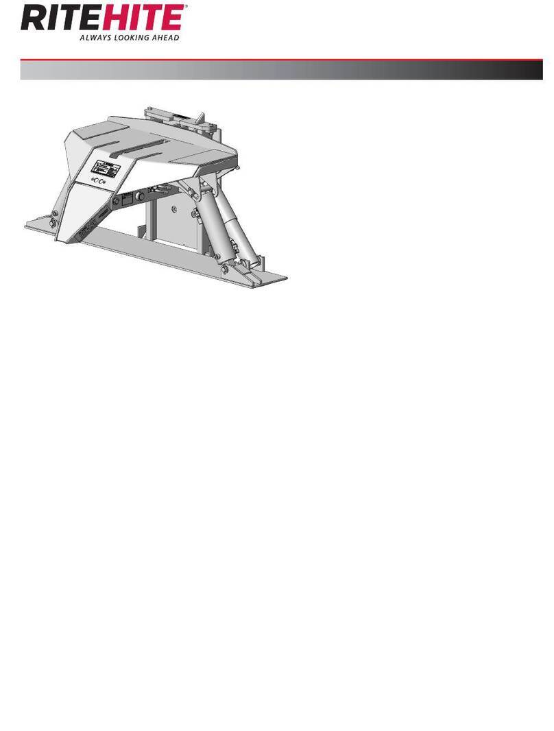
ATT NUSSBAUM SPRINTER MOBIL 2500 Installation instructions

SPRINTER MOBIL 2500
SPRINTER MOBIL 3000
Serial No.:
Serien Nr.:
HYMAX PRO 2500
HYMAX PRO 3000
Made
in
Germany
Operating manual | Inspection book
Betriebsanleitung | Prüfbuch
012

2SPRINTER MOBIL - HYMAX PRO 05.11.2015 20110005 OPI
is a brand of Otto Nußbaum GmbH & Co. KG

20110005 OPI 05.11.2015 SPRINTER MOBIL - HYMAX PRO 3
Contents Page
ENGLISH
1 Introduction______________________________ 5
2 General information ______________________ 6
2.1 Set up and test the system. _____________________6
2.2 Hazard information ____________________________6
3 Safety regulations ________________________ 6
3.1 Safety inspection ______________________________7
4 Assembly and commissioning_____________ 7
4.1 Set up guidelines ______________________________7
4.2 Commissioning ________________________________7
4.3 Changing the assembly location _______________8
4.4 Selecting the anchors __________________________9
4.5 Assembly ______________________________________9
5 Operating manual_______________________ 10
5.1 Lifting the vehicle ____________________________ 11
5.2 Lowering the vehicle_________________________ 11
6 Maintenance and care of the
system__________________________________ 12
6.1 System maintenance plan ___________________ 12
6.1.1 As required or visible damage ________________ 12
6.1.2 Maintenance 1 x per year____________________ 12
6.1.3 Maintenance every 2 years __________________ 13
6.1.4 Maintenance every 6 years __________________ 14
6.2 Cleaning and care of the system _____________ 14
6.3 Cleaning and care of stainless steel___________ 14
7 Behavior in cases of error ________________ 16
7.1 Moving onto an obstacle ____________________ 17
7.2 Emergency discharge during blackout________ 17
8 Technical information____________________ 18
8.1 Technical data ______________________________ 18
8.1.1
SPRINTER MOBIL 2500 - HYMAX PRO 2500 ________18
8.1.2
SPRINTER MOBIL 3000 - HYMAX PRO 3000 ________18
8.2 Safety devices_______________________________ 18
9 System master sheet_____________________ 19
9.1 Manufacturer________________________________ 19
9.2 Purpose _____________________________________ 19
9.3 Changes to the design / construction_________ 19
9.4 Changing the assembly location _____________ 19
10 Data sheet ______________________________ 20
11 Hydraulic plan __________________________ 21
12 Spare parts lists__________________________ 22
12.1
SPRINTER MOBIL 2500 - HYMAX PRO 2500 ________22
12.2 SPRINTER MOBIL 3000 - HYMAX PRO 3000 ______ 29
13 Set up protocol__________________________ 36
13.1 Transfer protocol_____________________________ 37
14 Safety inspection ________________________ 38
14.1 Single safety inspection before commissioning 38
14.2 Regular safety inspection and maintenance __ 39
14.3 Exceptional safety inspection ________________ 40
15 Electrical circuit diagram ________________ 77
15.1 230 V 1~/PE__________________________________ 79
15.2 230 V 3~/PE__________________________________ 83
15.3 230 V 3~/PE | 400 V 3~/PE ____________________ 87
15.4 400 V 3~/PE__________________________________ 91
15.5 400 V 3~/PE CE-STOP _________________________ 95
15.6 400 V 4-pole main switch ____________________ 101
16 Declaration of conformity _______________ 105
16.1 SPRINTER MOBIL_____________________________ 105
16.2 HYMAX PRO ________________________________ 106

4SPRINTER MOBIL - HYMAX PRO 05.11.2015 20110005 OPI
Inhalt Seite
DEUTSCH
1 Einleitung _______________________________ 41
2 Allgemeine Information__________________ 42
2.1 Aufstellung und Prüfung der Anlage __________ 42
2.2 Gefährdungshinweise________________________ 42
3 Sicherheitsbestimmungen________________ 42
3.1 Sicherheitsüberprüfung_______________________ 43
4 Montage und Inbetriebnahme ___________ 43
4.1 Aufstellungsrichtlinien ________________________ 43
4.2 Inbetriebnahme _____________________________ 44
4.3 Wechsel des Aufstellungsortes ________________ 44
4.4 Auswahl der Dübel___________________________ 45
4.5 Montage____________________________________ 46
5 Bedienungsanleitung ____________________ 46
5.1 Anheben des Fahrzeuges ____________________ 47
5.2 Senken des Fahrzeuges ______________________ 47
__________ 48
6.1 Wartungsplan der Anlage ____________________ 48
6.1.1 Bei Bedarf oder sichtbarer Beschädigung _____ 48
6.1.2 Wartung 1 x jährlich __________________________ 48
6.1.3 Wartung alle 2 Jahre _________________________ 50
6.1.4 Wartung alle 6 Jahre _________________________ 50
_____________ 50
___________ 51
7 Verhalten im Störungsfall_________________ 52
7.1 Auffahren auf ein Hindernis___________________ 52
7.2 Notablass bei Stromausfall____________________ 53
8 Technische Information __________________ 54
8.1 Technische Daten ___________________________ 54
8.1.1
SPRINTER MOBIL 2500 - HYMAX PRO 2500 ________54
8.1.2
SPRINTER MOBIL 3000 - HYMAX PRO 3000 ________54
8.2 Sicherheitseinrichtungen _____________________ 54
9 Stammblatt der Anlage __________________ 55
9.1 Hersteller ____________________________________ 55
9.2 Verwendungszweck _________________________ 55
9.3 Änderungen an der Konstruktion _____________ 55
9.4 Wechsel des Aufstellungsortes ________________ 55
10 Datenblatt ______________________________ 56
11 Hydraulikplan ___________________________ 57
12 Ersatzteillisten ___________________________ 58
12.1
SPRINTER MOBIL 2500 - HYMAX PRO 2500 ________58
12.2 SPRINTER MOBIL 3000 - HYMAX PRO 3000 ______ 65
13 AufstelIungsprotokolI ____________________ 72
13.1 Übergabeprotokoll___________________________ 73
14 Sicherheitsprüfungen ____________________ 74
14.1 Einmalige Sicherheitsprüfung vor Inbetriebnahme
_____________________________________________ 74
14.2 Regelmäßige Sicherheitsprüfung und Wartung 75
14.3 Außerordentliche Sicherheitsprüfung _________ 76
15 Elektroschaltplan ________________________ 78
15.1 230 V 1~/PE__________________________________ 79
15.2 230 V 3~/PE__________________________________ 83
15.3 230 V 3~/PE | 400 V 3~/PE ____________________ 87
15.4 400 V 3~/PE__________________________________ 91
15.5 400 V 3~/PE CE-STOP _________________________ 95
15.6 400 V 4-pol. Hauptschalter __________________ 101
16 Konformitätserklärungen________________ 105
16.1 SPRINTER MOBIL_____________________________ 105
16.2 HYMAX PRO ________________________________ 106

ENGLISH Translation
1 Introduction
Nußbaum products are a result of many years
of experience. A high quality standard and su-
perior concept guarantees you reliability, long
lifetimes and economical operation. To prevent
unnecessary damage and hazards, read this ope-
rating manual carefully and always comply with its
contents.
!Any other use, or use beyond purpose is
considered improper.
!Otto Nußbaum GmbH & Co.KG is not liable for
any resulting damage. The operating compa-
ny alone carries the risk.
Proper use also includes:
Adherence to all instructions in this operating
manual.
Compliance with inspection and maintenance
work and the inspections stipulated.
The operating manual is to be followed by all
personnel working on the system. This is notably
with regards to Section 3 „Safety conditions.“
In addition to safety information from the
operating manual, comply with rules and regula-
tions at the location of use.
Proper system handling.
Operating company obligations:
The operating company is obliged to only permit
personnel to work on the system who
Understand the principle regulations about work
safety and accident prevention and who have
been trained in working with the system.
Have read the safety section and warning infor-
mation in this operating manual, have under-
Hazards in working with the system:
Nußbaum products have been designed and
built to state-of-the-art and to recognized safety
standards. However, improper use may lead to
hazards to life and limb of the user or result in
property damage.
The system may only be operated
For proper intended use
If it is technically in perfect condition
Organizational measures
The operating manual is always to be kept ready
at the location of use of the system.
Supplemental to the operating manual, refer to
and comply with generally valid legal and other
binding regulations for accident prevention and
for environmental protection.
Check occasionally that personnel have an
awareness of hazards and safe work in compli-
ance with the operating manual!
Use personal protective equipment as needed
or required by regulations.
All safety and hazard information on the system
is to be kept in a legible condition!
-
cations of the manufacturer. This is only guaran-
teed for original parts.
Deadlines pre-set or given in the operating
manual for repeating tests / inspections must be
followed.
Maintenance work, error removal
Comply with pre-determined setting, main-
tenance and inspection work and intervals
in the operating manual, including details for
may only be done by specialists who have parti-
cipated in a special factory training.
Guarantee and liability
In principle, our „General sales and supply con-
ditions“ apply.
Guarantee and liability claims for personal and
property damage are excluded if due to one or
more of the following causes:
Improper use of the system.
Improper assembly, commissioning, operation
and maintenance of the system.
Operating the system with defective safety de-
vices or improperly attached or non-functional
safety and protection devices.
Non-compliance with information in the
operating manual in terms of transport, storage,
assembly, commissioning, operation, mainte-
Independent construction changes to the sys-
tem.
Independent changes to the system (e.g. drive
ratios: power, rotation speed, etc.)

6SPRINTER MOBIL - HYMAX PRO 08.12.2015 20110005 OPI
Improperly done repairs.
force majeure.
2 General information
Technical documentation contains important in-
formation for safe operation and for retaining
functional safety of the system.
To verify system set up, the set up protocol form is
to be signed and sent to the manufacturer.
Forms are available in this inspection book for
use in verifying single, regular and extraordina-
ry safety checks. Use the forms to document in-
spections and leave the completed forms in the
inspection book.
The system master forms must record changes to
the construction and changes to set up location.
2.1 Set up and test the system.
Safety relevant work on the system and safety
inspections may only be done by personnel speci-
in general and in this documentation as technical
experts and specialists.
Technical experts are people (freelance expert
engineers, TÜV specialists) that may inspect and
assess due to their education and experience
with lift systems. They are knowledgeable in the
appropriate work safety and accident preventi-
on regulations.
Specialists (competent people) are people who
lift systems and have participated in a special
factory training by the system manufacturer.
2.2 Hazard information
To become aware of the hazardous points and
important information, the following three symbols
are used with the descriptive meaning. Pay parti-
cular attention to text positions that are labeled by
these symbols.
iNote! Labels information about a key function
or points to an important remark!
!
damage or other operating company property
damage if the highlighted process is not done
properly!
Danger !
and limb, if the highlighted process
is not done properly there is a mortal
danger!
3 Safety regulations
When working with systems comply with legal
accident prevention regulations according to
BGG 945, inspection of lifts; BGR 500 and operation
of systems; VBG 14.
Particular attention is drawn to compliance with the
following regulations:
When operating the system, follow safety regula-
tions and operating instructions in the operating
manual.
The total weight of the accepted load may not
exceed
- 2,500 kg for SPRINTER MOBIL 2500 - HYMAX PRO
2500 and
- 3,000 kg for SPRINTER MOBIL 3000 - HYMAX PRO
3000,
where a maximum load distribution of 3:2 or 2:3
in or against the drive-in direction is permitted.
Only personnel aged 18 or over may operate
systems independently, they must be trained in
the company. They must be explicitly tasked with
operating the system (excerpt from BGR 500),
see transfer protocol.
Operation of the system is only permitted on a
smooth, solid surface.
During lifting or lowering, the work area of the
system should be clear or people.
It is prohibited from moving people with the lift.
It is prohibited to climb onto the system.
After design and maintenance on load bearing
parts the system must be inspected by a techni-
cal expert.
Initial access into the system may only be done
after the main switch (2) is off and locked.
equipment, check in advance whether it could
be damaged.
Consider any possible centre of mass shifts when
disassembling heavy vehicle components.

20110005 OPI 08.12.2015 SPRINTER MOBIL - HYMAX PRO 7
3.1 Safety inspection
The safety inspection is required to guarantee
operational safety of the lift system. It is to be done:
lift system use the „single safety inspection“
form
least once per year.
Use the „regular safety inspection“ form
3. After changes to the lift system construction
Use the „extraordinary safety inspection“ form
!Single and regular safety inspections must be
done by a specialist. It is recommended to do
maintenance at the same time.
iAfter a change in construction (for examp-
le changing the load carrying capacity or
changing the lifting height) and after signi-
(e.g. welding work), inspection by a technical
expert is required (extraordinary safety inspec-
tion)
This inspection book contains forms with a detailed
inspection plan for safety inspections. Please use
the appropriate form, record the condition of the
inspected system and leave the completed form
in this inspection book.
4 Assembly and commissioning
4.1 Set up guidelines
There is the option to anchor the lift on an exi-
concrete thickness min. 160 mm (normal rein-
forcement).
To protect the electrical cable all cable condu-
plastic pipes.
commissioning, the operating company must
have the lift grounding conductors inspected
on-site according to IEC regulation (60364-6-61).
An insulation resistance test is also recommen-
ded.
The anchoring of the lift must be carried out
by trained manufacturer personnel or a contract
partner. If the operating company has appropri-
ately trained assemblers, the system can also be
set up by them. Set up is to be done according
to the assembly instructions.
A standard system may not be set up in explosi-
on endangered spaces or wash halls.
Provide an on-site electrical connection of 3 ~/N
+ PE, 400 V, 50 Hz, fuses with 16 A, slow.
iThe foot bumper (15) must always be mounted
with the orange sticker (16) on the side where
the cylinder (17) is located.
15 Foot bumper 022
16 Orange sticker
17 Cylinder
18 Load capacity Sticker
4.2 Commissioning
iThe SPRINTER MOBIL - HYMAX PRO has been
inspected and accepted by Nußbaum. The
test need no longer be carried out by a speci-
alist before initial commissioning.
18 16
15 17
2
1
3
4
1 Cover hood
2 Main switch
3 "LIFT" button
4 "LOWER" button

8SPRINTER MOBIL - HYMAX PRO 08.12.2015 20110005 OPI
- Remove the front cover hood (1)
- Loosen and remove the sealing screw (5) of the
oil tank
Fill new hydraulic oil (e.g. HLP 32). About 8 litres
are needed.
Provide an on-site electrical connection of 3 ~/N
+ PE, 400 V, 50 Hz, fuses with 16 A, slow.
Connect the electric cable to the customer-pro-
vided mains breaker (e.g. a Cekon plug).
003
Turn on main switch (2) and press the „LIFT“
button (3).
!If the lift does not move upwards after a few
seconds, the direction of rotation of the motor
is incorrect. Swap 2 phases on the plug.
Then press the „LIFT“ button (3) again and rai-
se and lower the lift to its limit positions several
times without load. This will largely ventilate the
hydraulic system.
4.3 Changing the assembly location
To operate the lift, it must be raised about
500 mm so that the back wheel axes (9) and
guide roller (6) can be engaged.
6 Guide roller 004
7 Torsion shaft
8 Towing bar
9 Wheel axles
Place the guide rollers (6) over the torsion shafts
(7). Then push them until the tappet (10) is
located in the notch (11) of the guide
roller.
6 Guide roller 005
10 Tappet 11 Notch
19 Guide roller holder
The wheel axles (9) are in the lower plate of the
lift (12).
9 Wheel axle 019
12 Wheel axle storage
iTo simplify mounting, it may be necessary to
raise or lower the lift a little.
Then lower the lift completely. Hang the tow
bar (8) into the guide roller (6) and the lift can then
be moved.
5
8
9
6
7
19
6
11
10
12
9

20110005 OPI 08.12.2015 SPRINTER MOBIL - HYMAX PRO 9
To remove the roller, follow the instructions in the
reverse order.
The mobile hand unit quickly makes the SPRINTER
MOBIL - HYMAX PRO ready to use again.
To change the setup location of an anchored lift,
the conditions according to the setup guidelines in
Section 4.1 must be ensured.
!Use new anchors. The old anchors are no lon-
4.4 Selecting the anchors
Safety anchor with threaded bolts and nuts
BM 10-15/70/40
Safety anchor with threaded bolts and nuts
High quality anchor FH II-B (bolts and nuts)
FH II 15/50 B
Heavy duty anchor
HSL-3-G M10/40
Heavy duty anchor
Hilti HIT-V-5.8/M10/130
iSimilar value anchors and other known brands
of anchor manufacturers can be used when
considering the conditions.
4.5 Assembly
iFollow the instructions enclosed in the anchor packaging.
011

10 SPRINTER MOBIL - HYMAX PRO 08.12.2015 20110005 OPI
5 Operating manual
When handling the system, it must ab-
solutely comply with safety regula-
tions. Carefully read the safety regula-
To prevent operation by unauthorized
-
ter working height has been reached.
Operating element 007
2 Main switch
3 „LIFT“ button
4 „LOWER“ button
For SPRINTER MOBIL - HYMAX PRO lifts,
the motor of the vehicle supported
side, otherwise the vehicle could fall.
The total centre of mass of the
vehicle and its load must be between
bearing towards the middle of the lift,
otherwise the vehicle could fall.
Slowly drive the vehicle to the middle in both the
lengthwise and crosswise directions over the drive-
in rails.
Vehicle with front-wheel drive:
008
Vehicle with rear-wheel drive:
009
3
2
4

20110005 OPI 08.12.2015 SPRINTER MOBIL - HYMAX PRO 11
010
5.1 Lifting the vehicle
!Warning! The hydraulic lines may not be driven
over. This can lead to damage and, if leaks re-
sult, even to the lift sinking.
!The total centre of mass must be considered.
iIf required, use the ramps for safe acceptance
of the vehicle.
Secure the vehicle against rolling; pull the hand
brake, engage the gears.
Inspect the hazardous area.
No person or object may stand in the working
area of the lift, or on the lift.
Switch on controls. Turn the main switch (2) to
Position polymer overlays below the points spe-
overlays may not be placed on edge, otherwise
the vehicle could fall.
Lift the vehicle. Push the „LIFT“ (3) button.
If the wheels are not blocked, interrupt the lifting
process and check for proper seating of the po-
lymer overlays.
Raise the vehicle to the desired working height.
Then position the operating unit in such a way
hydraulic hose) cannot be damaged by external
5.2 Lowering the vehicle
!Warning! The hydraulic lines may not be driven
over. This can lead to damage and, if leaks re-
sult, even to the lift sinking.
Inspect the hazardous area. No person or object
may stand in the working area of the lift, or on the
lift.
!The vehicles cannot be lowered into the lowest
position without wheels. Otherwise the lift can-
not raise the load using its own force. The vehi-
cle could be damaged.
015
Lower the vehicle to the desired working height.
The system is equipped with an optional CE-STOP
During „LOWER“ (4) to the lowest position, the
system stops at a height of 300 mm.
To allow the system to lower further, it is necessa-
ry to release the „LOWER“ button (4) and press it
again.
A signal tone sounds until the system has rea-
ched the lowest position.
The entire lowering process must be observed.
If the lift is in the detectable lowest position, re-
move the polymer overlays and drive the vehicle
from the lift.

12 SPRINTER MOBIL - HYMAX PRO 08.12.2015 20110005 OPI
6 Maintenance and care of the
system
Before maintenance, do all prepara-
tion work so there is no danger to life or
limb or object damage during mainte-
nance and repair work.
Value is placed on long lifetimes and safety in
the development and production of Nußbaum
products. To guarantee the safety of the opera-
tor, product reliability, low running costs, keep the
warranty and also the long-lifetime of the product,
proper set up and operation is just as important as
of the countries we supply to. For example, Eu-
experts every 12 months of work of the platform.
To guarantee the largest possible availability and
functional capacity of the lift system, ensure the
list of any cleaning, care and maintenance work
is done.
The lift system is to be serviced at regular inter-
vals according to the following plan. For intensive
operation and higher degree of contamination
shorten the service interval.
The complete function of the lift system is to be
observed during daily use. Customer service must
be informed of any malfunctions or leaks.
To simplify maintenance work, follow instructions
on the maintenance sticker that is found some-
where on the unit, depending on the lift design.
6.1 System maintenance plan
Before beginning service, disconnect
from power. The system is to be se-
cured against unintentional lowering
and unauthorized access.
6.1.1 As required or visible damage
6.1.2 Maintenance 1 x per year
Check condition of the model plate, load
capacity and sticker. Exchange them if
damaged or illegible.
Check condition of the Model plate, load capa-
city and sticker. Exchange them If damaged or
illegible.
Free the piston rod of the lifting cylinder of sand
and dirt.
Check the wiper for damage.
Moving parts such as joint bolts and DU bearings,
sliding pieces, sliding surfaces and rollers are to
be cleaned and checked for wear, exchange
if required.
Moving parts such as joint bolts, sliding pieces
and sliding surfaces are to be cleaned and che-
cked for wear and lightly greased. Do not over-
lubricate.
Check the polymer overlays and replace if re-
quired.
Check all available safety devices for function.
Check the state and function of the mobile set.
Check ease of motion of the tow bar (8), guide
roller (6) and wheel axles (9).
According to manufacturer instructions, the hy-
draulic oil should be changed every two years in
-
ences e.g. location, temperature swings, inten-
the quality of the hydraulic oil. For this reason,
the oil must be checked during annual safety in-
spections and maintenance.
The oil is used if it has a milky colour or if the hy-
draulic oil smells unpleasantly.
To change oil, lower the lift is to its lowest position
then suction the oil out of the oil container and
replace the contents.
The manufacturer recommends a high-quality
clean hydraulic oil. The required oil volume and
type is to be taken from the technical data. Af-
upper and lower marking on the oil dipstick, or
Dispose of the old oil according to regulations
-
-
disposal points).
All weld seams must have a visual inspection.
Stop the system and contact the manufacturer if
there are cracks or breaks in weld seams.
Check the powder coating and improve if re-
quired.
immediately after detection. If these points are
cause wide-ranging and permanent damage.

20110005 OPI 08.12.2015 SPRINTER MOBIL - HYMAX PRO 13
These points are to be lightly sanded (120 grit),
cleaned and degreased. Afterwards, rework
with a suitable touch up paint (note the RAL No.).
Check galvanized surfaces and touch up as
needed. White rust is fostered by permanent hu-
midity, poor ventilation.
Rust is brought out by mechanical damage, wear,
aggressive deposits (de-icing salt, leaking opera-
The affected areas can be treated by using a
sanding cloth (A 280 grit). If required, the parts
are to be treated with a suitable, resistant mate-
rial (paint etc.).
Check the protective hose and hydraulic hoses:
Check the condition of the protective hose
around the hydraulic lines. These should be ex-
changed if there is damage. During this, check
hydraulic lines for any crushing points (from third
Any affected lines must be exchanged. Other-
wise pressurized hoses must be exchange as re-
quired, however at latest after 6 years.
Hose lines are to be replaced:
for damage to the outer coating up to the in-
sert (chafe marks, cuts, cracks)
for brittleness of the outer coating (crack for-
mation), deformation of the natural shape in
the depressurized and in pressurized states.
if leaking
for damage or deformation of the mounting
if the lifetime has been exceeded
Repair of the hose line using the implemented
Extending the replacement intervals given in the
guideline is possible if the inspection for safe-
work condition is done in adjusted, shortened
time frames, if required and by competent per-
sonnel.
If ther is an extension of the replacement inter-
val, no situation may occur which could result in
injury of employees or other personnel.
For systems with aluminium panelling, these must
be removed to clean the drive in rails of dirt.
Check the torque of the fastening anchor.
The condition and function of the load suspensi-
on means are to be checked.
Check the torque of the fastening screws.
Also see the assembly protocol.
Torque (Nm) for shaft screws
Fastening class 8.8
0,08* 0,12** 0,14***
M8 17,9 23,1 25,3
M10 36 46 51
M12 61 80 87
M16 147 194 214
M20 297 391 430
M24 512 675 743
Fastening class 10.9
0,08* 0,12** 0,14***
M8 26,2 34 37,2
M10 53 68 75
M12 90 117 128
M16 216 285 314
M20 423 557 615
M24 730 960 1060
* Lubricated slide friction number 0.8 MoS2
** Lightly oiled slide friction number 0.12
*** Ensured slide friction number 0.14 screw with micro-
encapsulated plastic
sliding bearings. Despite this, due to environmen-
dirt) bearing zones may become noisy.
In this case, spray the affected areas with an
acid and resin free oil spray (no adhesive oil or
biologically degradable oil). Noises normally
occur after the system has been raised and lo-
wered several times.
Check the function of the CE STOP with warning
signal.
6.1.3 Maintenance every 2 years
Change the hydraulic oil according to manuf-
acturers instructions.

14 SPRINTER MOBIL - HYMAX PRO 08.12.2015 20110005 OPI
6.1.4 Maintenance every 6 years
Exchange the protective and hydraulic hoses.
Excerpt from BGR 237
6 years including 2 years storage time.
Increased demands e.g. due to increased
usage times, e.g. multi-shift operation, short cy-
cle times and pressure impulses and large ex-
hose lines:
2 year operation duration
6.2 Cleaning and care of the system
A regular and expert clean helps retain the value
of the system.
Additionally, it can also be a pre-requisiste for the
preservation of guarantee claims for any eventual
corrosion damage.
The best protection for the system is regular
removal of contaminants of any kind.
This includes above all:
De-icing salt
Sand, pebbles, earth
Industrial dust of all types
Water, also in connection with other environ-
Aggressive deposits of all types
-
on
The frequency of system cleaning depends,
among other things on the frequency of use, of
system handling, of workshop cleanliness, and the
location of the system.
Furthermore, the degree of contamination de-
pends on the time of year, the weather conditions
and workshop ventilation.
Under adverse circumstances, weekly system
cleaning might be required, however a monthly
Do not use and aggressive and abrasive materi-
als for cleaning, rather use mild cleaners, e.g. a
commercially available detergent and luke warm
water.
For cleaning, do not use high pressure washers
(e.g. steam cleaners).
Carefully remove all contamination with a
sponge, or if required with a brush.
Make sure that there is no residue of the cleaner
on the system.
Dry the system with a cloth and spray it with a
spray wax or oil.
6.3 Cleaning and care of stainless steel
be done with our stainless steel cleaner. We re-
commend our stainless steel cleaning spray (1) for
this.
Immediately remove iron particles, grinding dust,
swarf, and weld spatter. These foreign bodies can
accelerate rust if they are deposited on the stain-
less steel surface. The passive layer of the non-
corroding steel is broken and this leads to pinhole
corrosion.
To guarantee a perfect stainless steel, in princi-
ple we recommend regular cleaning and care
of stainless steel in exterior areas (at best every 6
months).
Contamination and deposits that have already
occurred or severe corrosive etching can be re-
moved with our special „Pelox“ cleaner (2).
For stainless steel products that are placed close
to seawater, seawater resistant products can be
implemented in V4A quality.
Detailed information can be found under
www.edelstahl-rostfrei.de.
All stainless steel parts from the Feldmann product
range are made from V2A or V4A with material
numbers 1.4301 or 1.4401104. The surface is ground
(mostly 240 grit).
parts can rust!
Stainless steel stands for a guarantee for long life-
time and elegance. To permanently retain the
high value of the surface, it is indispensable to take
care of and protect the material regularly.
-
ences or improper treatment.
How does rust bloom occur?
Environment related:
For higher humidity with salt content close to salt
water.
In industrial areas with particularly aggressive air
contamination (acid rain).
By surfaces in contact with de-icing salt spray
water close to streets.

20110005 OPI 08.12.2015 SPRINTER MOBIL - HYMAX PRO 15
By contact with chlorine water (V2A is not suita-
ble for swimming pools).
Assembly related:
During processing with tools that are in contact
with normal iron.
of the surface.
When the surface comes into contact with
building-chemical related foreign materials (cal-
cium, cement dust, etc.) that deposit on the sur-
face.
Aggressive cleaning materials.
1. Cleaner spray 7064-PF cleans, cares for and
protects stainless steel parts.
2. Pelox 7065-PE special cleaner for the strongest
3. Cleaner and preservative 50-ESP cleans and
protects (long term protection).

16 SPRINTER MOBIL - HYMAX PRO 08.12.2015 20110005 OPI
7 Behavior in cases of error
Defective operational readiness of the system may be due to a simple error. Check the system for the
listed sources of error.
If the error cannot be removed after an inspection to the named causes, then inform customer service
or your dealer.
Problem: Motor does not start
Possible causes: Remedy:
No power supply Check the power supply
The main switch (2) is not switched on, or is
defective Check the main switch (2).
Defective fuse Have fuses checked
"LIFT" (3) button defective Inform customer service
Motor defective Inform customer service
Problem: Motor starts, load is not lifted
Possible causes: Remedy:
Load is too heavy Unload the lift
Pressure line leaking Inform customer service
The connector for the left is designed for a
clockwise phase order.
Your power socket may not match. One of the
phases must be swapped.
Problem: The lift cannot be lowered
Possible causes: Remedy:
Lifting table is sitting on an obstacle See 7.1 Moving onto an obstacle
Hydraulic valve defective Inform customer service
"LOWER" (4) button defective Inform customer service
Incorrect push button actuated Push the correct push button

20110005 OPI 08.12.2015 SPRINTER MOBIL - HYMAX PRO 17
7.1 Moving onto an obstacle
If the system moves onto an obstacle during
lowering, then it remains in position due to the me-
chanical resistance. In this case the lift must be mo-
ved upwards by pushing the “LIFT” (3) button on the
operating panel until the obstacle can be remo-
ved. Afterwards the lift is in a normal work conditi-
on and can continue to be operated as described
in the operating manual.
7.2 Emergency discharge during blackout
An emergency discharge is an access
into the system controls and may only
be done by experienced specialists.
The emergency discharge must be
done in the following described se-
quence, otherwise it can lead to
damage and hazard to life and limb.
Any kind of external leakage is not
permitted and must immediately
taken care of. This is absolutely neces-
sary especially before an emergency
discharge.
Reason which make an emergency discharge
necessary are for example, electrical blackout, for
errors in the lowering valves, etc.
1. Switch off the main switch (2)
2. Loosen and remove the front unit covers (1).
3. Valve pins V1 and V2 must be pushed
from above simultaneously using a suitable
(e.g. screwdriver).
13 Valve V1
14 Valve V2
4. The lowering process starts immediately.
5. The entire lowering process must continuously
be observed. Observe the reaction of the
vehicle.
6. Let the valve down in case of danger.
7. Lower the vehicle to the lowest position.
13 14 5

18 SPRINTER MOBIL - HYMAX PRO 08.12.2015 20110005 OPI
8 Technical information
8.1 Technical data
8.1.1
SPRINTER MOBIL 2500 - HYMAX PRO 2500
System load capacity 2,500 kg
Load distribution Max. 3:2 or 2:3 in or
against the drive- in direction
(Consider the centre
of mass of the vehicle)
Effective lifting range
of the system Approx. 990 mm
System lift time Approx. 15.8 s
with 2,500 kg load
System lowering time Approx. 10.8 s
with 2,500 kg load
Operating pressure Approx. 220 bars
Pressure relief valve Approx. 260 bars
Filling volume oil container Approx. 8 litres
on-site connection 3~/N+PE, 400 V, 50 Hz
with 16 A fuses, slow,
according to VDE regulations
8.1.2
SPRINTER MOBIL 3000 - HYMAX PRO 3000
System load capacity 3,000 kg
Load distribution Max. 3:2 or 2:3 in or
against the drive- in direction
(Consider the centre
of mass of the vehicle)
Effective lifting range
of the system Approx. 990 mm
System lift time Approx. 16.9 s
with 3,000 kg load
System lowering time Approx. 10.9 s
with 3,000 kg load
Operating pressure Approx. 240 bars
Pressure relief valve Approx. 260 bars
Filling volume oil container Approx. 8 litres
on-site connection 3~/N+PE, 400 V, 50 Hz
with 16 A fuses, slow,
according to VDE regulations
8.2 Safety devices
Hydraulic system fuse against over-pressure.
Secure against lifting and lowering the system
too fast.
Fuse to prevent unauthorized use.
The corresponding movement stops when the
operating button ("LIFT" (3) or "LOWER" (4)) is re-
leased.
Protection against crushing.
Secure against shear and crushing points in the
foot area.

20110005 OPI 08.12.2015 SPRINTER MOBIL - HYMAX PRO 19
9 System master sheet
9.1 Manufacturer
Otto Nußbaum GmbH & Co.KG
Korker Straße 24
D-77694 Kehl-Bodersweier
9.2 Purpose
The SPRINTER MOBIL - HYMAX PRO lift is a lifting accessory for the lifting of vehicles up to a total weight
of 2,500 kg or 3,000 kg, in normal workshop operation at a maximum load distribution of 3:2 in or against
the drive-in direction.
Additionally, there is a distinction between cars operated with front or rear drive.
The lift is not set up for standing on the receiving plate or for personnel conveyance.
The set up of the standard lift is not permitted in explosion endangered work shops.
inspected afterwards by a specialist who approves the changes.
Operation of the lift is done by an operating unit that is located immediately next to the lift.
9.3 Changes to the design / construction
Inspections by a technical expert are required before recommissioning (date, type of change, technical
expert signature).
.................................................................................................................................................................................
......
.................................................................................................................................................................................
......
Name, address of technical expert
......................................................................................... ..................................................................................
......
Location, date Technical expert signature
9.4 Changing the assembly location
Inspections by a technical expert are required before recommissioning (date, type of change, specialist
signature).
.................................................................................................................................................................................
......
.................................................................................................................................................................................
......
Name, address of technical expert
......................................................................................... ..................................................................................
......
Location, date Technical expert signature

20 SPRINTER MOBIL - HYMAX PRO 08.12.2015 20110005 OPI
10 Data sheet
SPRINTER MOBIL 2500 - HYMAX PRO 2500
SPRINTER MOBIL 3000 - HYMAX PRO 3000
7686_NB 05.11.2014 018
This manual suits for next models
3
Table of contents
Languages:
Other ATT NUSSBAUM Lifting System manuals
