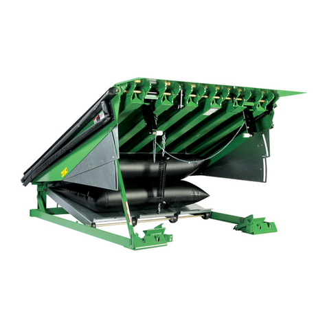
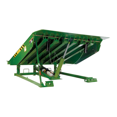
Kelley aFX-C User manual

Do not install, operate or service this product unless you
have read and understand the Safety Practices, Warnings,
Installation and Operating Instructions contained in this
User’s Manual. Failure to do so could result in death or
serious injury.

Indicates an imminently hazardous situation which,
if not avoided, will result in death or serious injury.
Indicates a potentially hazardous situation which, if
not avoided, could result in death or serious injury.
Indicates a potentially hazardous situation which, if
not avoided may result in minor or moderate injury.
Notice is used to address practices not related to
personal injury.
This is the safety alert symbol. It is used
to alert you to potential personal injury
hazards. Obey all safety messages that
follow this symbol to avoid possible death or injury.

Read these Safety Practices before installing, operating
or servicing the dock leveler. Failure to follow the safety
practices could result in death or serious injury.


RAMP and LIP grades, % for each dock leveler length
6' Leveler 8' Leveler 10' Leveler
VEHICLE
PLATFORM
POSITION from
DOCK, (in.) RAMP LIP RAMP LIP RAMP LIP
A
B
O
V
E
D
O
C
K
18.0
16.0
14.0
12.0
10.0
8.0
6.0
4.0
2.0
--
--
--
20.5
17.6
14.7
11.9
9.1
6.3
--
--
--
8.0
5.0
2.2
-0.7
-3.5
-6.3
--
--
--
15.3
13.1
11.0
8.9
6.8
4.7
--
--
--
2.7
0.6
-1.6
-3.7
-5.8
-7.9
17.3
15.6
13.9
12.2
10.5
8.8
7.1
5.4
3.8
4.8
3.0
1.3
-0.4
-2.1
-3.8
-5.5
-7.1
-8.8
0.0 3.5 -9.1 2.6 -10.0 2.1 -10.5
B
E
L
O
W
D
O
C
K
-2.0
-4.0
-6.0
-8.0
-10.0
-12.0
0.7
-2.1
-4.9
-7.7
-10.5
-13.3
-11.9
-14.6
-17.4
-20.2
-23.0
-25.9
0.5
-1.6
-3.6
-5.7
-7.8
-9.9
-12.0
-14.1
-16.2
-18.3
-20.4
-22.5
0.4
-1.2
-2.9
-4.6
-6.3
-7.9
-12.1
-13.8
-15.5
-17.1
-18.8
-20.5
Optional 7° lip bend, 16" lip
VEHICLE
PLATFORM
POSITION from
DOCK, (in.)
RAMP and LIP grades, % for each dock leveler length
6' Leveler 8' Leveler 10' Leveler
RAMP LIP RAMP LIP RAMP LIP
A
B
O
V
E
D
O
C
K
18.0
16.0
14.0
12.0
10.0
8.0
6.0
4.0
2.0
--
--
--
19.4
16.5
13.7
10.8
8.0
5.2
--
--
--
11.6
8.7
5.8
3.0
0.2
-2.6
--
--
--
14.5
12.3
10.2
8.1
6.0
3.9
--
--
--
6.6
4.5
2.4
0.2
-1.8
-3.9
16.7
15.0
13.2
11.5
9.8
8.2
6.5
4.8
3.1
8.8
7.1
5.4
3.7
2.0
0.3
-1.4
-3.1
-4.7
0.0 2.4 -5.4 1.8 -6.0 1.5 -6.4
B
E
L
O
W
D
O
C
K
-2.0
-4.0
-6.0
-8.0
-10.0
-12.0
-0.3
-3.1
-5.9
-8.7
-11.5
-14.4
-8.2
-11.0
-13.8
-16.6
-19.4
-22.2
-0.3
-2.3
-4.4
-6.5
-8.6
-10.7
-8.1
-10.2
-12.3
-14.4
-16.5
-18.6
-0.2
-1.9
-3.5
-5.2
-6.9
--
-8.1
-9.7
-11.4
-13.1
-14.7
--
4° lip bend, 16" lip
Ramp Grade
Lip Grade

Place barricades around pit on dock oor and drive while
installing, maintaining or repairing dock leveler.
Before installing the dock leveler, read and follow the
Safety Practices on page 3. Failure to follow the Safety
Practices could result in death or serious injury.
10"
12"-13"
Box Located as
Shown
Pit
Center
Line
Push-Button
Control Station
48"

Inadequate lifting equipment or practices can cause a
load to fall unexpectedly. Make sure the lifting chain or
other lifting devices are in good condition and have a
rated capacity of at least 3,500 lbs for the lifting angle
used. Never allow anyone to stand on or near the dock
leveler when it is lifted or placed into the pit. Stand clear
of the dock leveler when it is placed into the pit. Failure
to follow this warning can allow the dock leveler to fall,
tip, or swing into people, resulting in death or serious
injury.
Route power cord clear of edges and resting surfaces
so that it is not damaged during lifting and placement.
Plug end may be routed up through the rear hinge until
needed.
3/4" - 10 UNC
load centering
eyebolt

The rear edge of the dock leveler should be level or
slightly (1/16" maximum) below dock level.
The top surface of the dock leveler should be level and a
smooth transition with the dock oor curb steel. The front
end should be level and parallel with the rear frame angle
for proper operation. Unequal adjustment of the front
supports may be required to obtain a level front edge.
Turn off all electrical power to the leveler if it has been
previously connected. Welding with dock levelers power
connected can damage the electrical components. A
ground must be attached to the leveler frame.
1/2"

Before welding the dock leveler supports to the front curb
angle make sure that the dock leveler support legs line
up with the "V" pocket in the dock leveler support angle
and that the leg roller is centered over the its roller track.
Move dock levelers support right or left for the necessary
alignment.
Rear Pit
Curb Angle
Pit Side Curb Angle
Ramp
Rear
Frame
Angle
Equal Gap
Frame
Uprights Rear Hinge
Assembly
Pit
Rear
Curb
Angle
2-1/2"
5"
2-1/2"
5"
5"
5"
2-1/2"
5"
2-1/2"
5"
Raises
rear
angle
Transition angle
Curb
angle
1/4"
Legs are in contact
with pit floor when
the leveling screws
are 1/4" from the
top of the transition
angle
Leg
adjustment

The lifting support frame will drop rapidly to the pit oor
when the retainer bolts are removed. Keep your hands
and feet out from under the dock leveler when releasing
the frame. Failure to do so could result in death or serious
injury.
Air pressure or mechanical support must be maintained
under the ramp to hold it in the raised position until the
maintenance strut is in place. DO NOT WORK UNDER
THE DOCK LEVELER RAMP OR LIP UNLESS THE
MAINTENANCE STRUT IS IN PLACE AND PINNED, AND
LIP LOCK IS IN PLACE AND SUPPORTING THE LIP.
Flush with floor at this point
Door jamb
1/2" sq. drive
adjustment bolt
CCW rotation
to raise
3/16" weld
(both sides)
3/16" weld
3" long (min.)
(both sides)
3/16" weld
(both sides)
3/16" weld
3" long (min.)
(both sides)
3/16" weld
3" long (min.)
3/16" weld
3" long (min.)
3/16" weld
Curb steel
Curb steel
Shipping tie
down bolt

Retaining Bolts
Remove
Shipping Cotter
Pins
Manual support of the lip must be maintained until the lip
lock is in place. The lip is free to move downward when
it is released unless the lip lock is in position supporting
the lip. DO NOT WORK UNDER THE DOCK LEVELER
RAMP OR LIP UNLESS THE MAINTENANCE STRUT IS IN
PLACE AND PINNED, AND LIP LOCK IS IN PLACE AND
SUPPORTING THE LIP.
Maintenance
strut bracket
Insert hairpin
clip through
maintenance
strut pin
Maintenance
strut pin
Maintenance
strut
Lip Lip
lock

Improper installation of anchoring devices or installation
into aged or unsound concrete could result in death or
serious injury.
The dock face must be ush with curb angle to assure
proper bumper mounting.
Manually support the lip when storing the lip lock. Stand
clear of the lip when removing support. The lip is free to
move downward when support is removed. Anyone in the
path of the lip when it moves downward can be struck.
Keep your hands, ngers and head away from the lip
when it is released. They could be struck by the lip or
caught between the lip and other parts of the dock leveler
resulting in death or serious injury.
DO NOT MOVE THE MAINTENANCE STRUT WITHOUT
AIR PRESSURE IN THE BAG OR A MECHANICAL LIFTING
DEVICE SUPPORTING RAMP. Raise the ramp using air
pressure or a mechanical device before storing the
maintenance strut. Stand clear of the ramp and lip when
air pressure or the mechanical lift is applied or removed.
The ramp and lip are free to move downward when the
support is removed. Removing the support without air
pressure will allow the ramp and lip to drop RAPIDLY. If
the dock leveler was raised using a mechanical device,
lower it using the same device.
Vertical
Bumper
Mounting
Angle
LAMINATED BUMPERS
3/4" Dia.
Anchor
Bolt.
Field
Installed.
Supplied
by Others.
3/8" Side of Pit
to Side of Bumper
Mounting Plate
1/4"
Laminations Must Be
Installed Vertically
Weld Full Length of
Bumper Mounting
Plate. Downhill Welds
are Unacceptable.
1/4"
To
Curb
Angle

Warning and Operating
Instruction Placard
The hinged lip will extend as the ramp moves down.
Improper installation that allows the pendant dock leveler
lip to support the weight of the dock leveler could result
in death or serious injury. It is sometimes necessary to
install lip deector plates to avoid any chance of the
pendant lip supporting the weight of the dock leveler
either near dock level or during a below dock end load.

Shim and weld flush
Equal
gap 1/2" max.
1/8" MAX
Allowable Step
No Greater than
1" x 3" in size
6"
Contact
Zone

Before doing any electrical work, make certain the power
is disconnected and properly tagged or locked off. All
electrical work must be done by a qualied technician
and meet all applicable codes. If it is necessary to make
troubleshooting checks inside the control box with the
power on, USE EXTREME CAUTION. Do not place your
ngers or non insulated tools inside the control box.
Touching wires or other parts inside the control box
could result in electrical shock, death or serious injury.
Never allow more than 130 volts to be connected to the
120 volt motor circuit. Damage to motor, push-button, air
bag, and serious personal injury or death may result.
Optional Blue Contact Block
(Normally Closed)
Field Installed (Low Voltage Only)
See Supplied Mfg. Instructions
Control
Station
Control
Station Optional Connection to Restraint
Star 4 Module Limit Switch
Terminals No. 21 and No. 22
To: Auto Chock Terminal Block
Terminals No. 5 and No. 24
Pit Wall
Receptacle
NEMA 5-15R
(By Others)
Pit Wall
Receptacle
NEMA 5-15R
(By Others)
1 Phase 120V
50/60 Hz
1 Phase 120V
50/60 Hz
BLK
WHT
GRN Motor
BLK
WHT
GRN Motor
Circuit Breaker
(By Others)
20 AMP MAX
Circuit Breaker
(By Others)
20 AMP MAX
Line
Line
Grn
Grn
Neutral
Neutral
120V
1 Phase
50/60 Hz
120V
1 Phase
50/60 Hz
120V, Single Phase, 50/60 Hz
Optional Dual Contact
120V, Single Phase, 50/60 Hz
Single Contact

Before operating the dock leveler, read and follow the
Safety Practices on page 3.
Use of dock leveler restricted to trained operators. Follow
procedures on placard posted near dock leveler.
DO NOT USE THE DOCK LEVELER IF IT LOOKS
BROKEN, OR DOES NOT SEEM TO WORK RIGHT. Tell
your supervisor it needs repair right away, or contact
your local Kelley distributor.
Before pressing button, ensure lip avoids contact with
vehicle sides and cargo. If lip does not lower to vehicle
oor, reposition vehicle.
Stay clear of leveler unless lip is supported by vehicle
oor or the leveler is stored at dock level. Visually check
that the lip is supported by the vehicle oor or the ramp
is supported by both front dock level supports before
driving or walking on the ramp. Unsupported dock
levelers can lower unexpectedly.
Before chocking wheels or engaging vehicle restraint,
dump air from air ride suspensions and set parking
brakes.
Always be certain that the vehicle wheels are chocked,
or that the vehicle is locked in place by a vehicle
restraining device and the brakes are set before loading
or unloading. Vehicles pulling away from the dock
unexpectedly can cause uncontrolled drop of the dock
leveler which can result in death or serious injury.
The maximum uncontrolled drop of a KELLEY® aFX-C
leveler, if above dock level, would be to dock level, and if
below dock level would be to the full below dock position.
Always return the dock leveler to its dock level (stored)
position before allowing the vehicle to leave the dock.
If the vehicle pulls away from the dock before the dock
leveler is stored, the lip will fall to its pendant position
and the ramp will drop. In addition, failure to properly
store the leveler may leave the leveler in a position below
the level of the dock oor. This condition may result
in unexpected drop of personnel or material handling
equipment and result in death or serious injury.
Failure to follow these instructions could result in death
or serious injury to operators and/or bystanders.

Dock Level
Supports
Push to Raise
Lip Extend Ramp
Vehicle Bed

Do not drive on dock leveler or lip until it is fully extended
and supported by the vehicle platform.
Never use a fork truck or other material handling
equipment to lower the ramp and lip sections.
Never drive on the dock leveler with the lip resting on
the trailer and the dock level support legs engaging their
lower supports at the same time.
If a trailer rises during loading or unloading enough to
cause the dock level support legs to engage their lower
supports with the lip of the leveler in the trailer, the
operator must get off the leveler and re-deploy the leveler
into the trailer. This will allow the legs to get out of the
way and will allow oat of the leveler again. If this is not
done, damage to the legs and leveler may occur.
The likelihood of this event occurring can be greatly
reduced by the practice of exhausting the air from the
trailer's air ride suspension before deploying the dock
leveler.
Before allowing vehicle to leave always return the dock
leveler to its dock level (stored) position with the dock
level support legs supported by the front dock level
supports and the lip hanging pendant. See Fig. 27. Failure
to do so may leave the leveler in a position below the level
of the dock oor. This condition may result in unexpected
drop of personnel or material handling equipment and
result in death or serious injury.
Front Angle
Dock Level
Support
Dock Level
Support Leg

Below Dock
Control (BDC) Chain
Before allowing vehicle to leave always return the dock
leveler to its dock level (stored) position with the dock
level support legs supported by the front dock level
supports. See Fig. 27. Failure to do so may leave the
dock leveler in a position below the level of the dock
oor. This condition may result in unexpected drop of
personnel or material handling equipment and result in
death or serious injury.

138-837 (x2)
6008485 (x2)
6001952
921-070
(x2)
921-074
Danger and operation placard
(mounted on wall near leveler)
6015283
Table of contents
Other Kelley Lifting System manuals
Popular Lifting System manuals by other brands

AMSAN
AMSAN AM-FPL9 manual

Challenger Lifts
Challenger Lifts CL4P9S Installation, operation & maintenance manual

Schmalz
Schmalz VACUMASTER COIL operating instructions

Aqua Creek Products
Aqua Creek Products EZ Series manual

IDEAL
IDEAL MSC-6KLP Installation & operation manual

Grabo
Grabo OTTOVAC Operator's manual

Braun Corporation
Braun Corporation NL500 Series Service manual

EINHELL
EINHELL BT-PT 2500 Original operating instructions

Skyjack
Skyjack SJIII 6826E operating manual

WPG
WPG P1HV1102DC3 operating instructions

Launch
Launch TLT235 user manual

Safety Clamps
Safety Clamps VL-BC Operation, maintenance, and repair manual