Attero Tech Dante unD6IO-BT User manual

APPENDIX F
PAGE 1 OF 123
HMC 8EH Burn Upgrades
UW Project Number: 206970
Ankrom Moisan Architects
March 16, 2020
AMA PROJECT NUMBER 192190 Section Prepared by Stantec
APPENDIX F
THIS SECTION IS SUBMITTED FOR REFERENCE ONLY
ALL CONTRACTOR REQUIRED SCOPE IS INDICATED ON THE DRAWINGS
1. Narrative
2. Bluebeam markup
3. Datasheets
4.OOPC (Equipment List and Probable Cost)

HMC 8EH Burn Upgrades 27 41 16.20
UW Project Number: #206970 AUDIO-VIDEO SYSTEMS NARRATIVE
Ankrom Moisan Architects PAGE 1 OF 2
March 25, 2020
AMA PROJECT NUMBER 191360 Section Prepared by Stantec
PART 1 - GENERAL
1.1 SUMMARY
A. This section contains the general narrative that applies to the Audio-Video Sections of Division
27. Materials and equipment shall be installed in conformance with the manufacturer's
installation instructions and U.L. requirements.
B. It is the intention of this Division of the Specification and the accompanying drawings to
describe and provide for the completion of design details, furnishing, installing, testing and
placing in satisfactory and fully commissioned operational condition all equipment, materials,
devices and necessary appurtenances to provide a complete and fully operational Audio-Video
(AV) systems, together with such other miscellaneous installation and equipment hereinafter
specified and/or shown on the drawings.
C. The drawings and specifications are complementary and what is called for (or shown) in either
is required to be provided as if called for in both. Where conflicting information occurs within the
drawings and specifications or between the drawings and specifications, the more expensive
alternative shall be used as a basis for bidding. Prior to execution of the contract, Contractor
shall notify Consultant of all conflicts between the drawings and specifications.
1.2 NARRATIVE
A. Play Room
1. The Playroom interactive audio video system is designed to provide video entertainment
and interactive content via Multitouch display and applications loaded on connected
computer like using a large iPad.
2. The Playroom video display consists of a 98” 12 point Multitouch LCD video display.
3. The Playroom will offer the following capabilities:
a. Audio System
1) Two zones of monaural electronic amplification, reproduction of audio from
video content.
2) Five quality loudspeakers located in ceiling to provide area with full fidelity
sound.
3) Audio input plate with Bluetooth located to the left of the display.
4) Two sets of RF wireless rechargeable headphones.
b. Video System
1) One 98” twelve points of touch Multitouch LCD display located on head wall.
2) HDMI and USB computer input located to the left of the display.
3) One rack mounted owner furnished computer will run applications for
interactive content.
4) One 8x2 matrix switcher to accommodate five media devices and one wall
plate.
c. Control System
1) Volume control of inputs, video selection, and remote power control at a
touch control panel in a 2 Gang wall box.
d. Equipment Rack

HMC 8EH Burn Upgrades 27 41 16.20
UW Project Number: #206970 AUDIO-VIDEO SYSTEMS NARRATIVE
Ankrom Moisan Architects PAGE 2 OF 2
March 25, 2020
AMA PROJECT NUMBER 191360 Section Prepared by Stantec
1) The equipment will reside in a 16 space cabinet rack with an Uninterruptible
Power Supply.
B. Therapy Room
1. The Therapy room interactive audio video system is designed to provide video
entertainment and interactive content via Multitouch video wall and applications loaded
on connected computer like using a large iPad.
2. The Therapy Room video display consists of a Multitouch 2X2 46” LCD video wall.
3. The Therapy Room will offer the following capabilities:
a. Audio System
1) Two zones of monaural electronic amplification, reproduction of audio from
video content.
2) Three quality loudspeakers located in ceiling to provide area with full fidelity
sound.
3) Audio input plate with Bluetooth located to the left of the display.
Two sets of RF wireless rechargeable headphones.
b. Video System
1) One twelve-point Multitouch 2x2 46” LCD video wall located on head wall
with surge protection installed.
2) HDMI and USB computer input located to the left of the display.
3) One rack mounted computer will run applications for interactive content.
4) One 8x2 matrix switcher to accommodate five media devices and one wall
plate.
c. Control System
1) Volume control of inputs, video selection, and remote power control at a
touch control panel in a 2 Gang wall box.
d. Equipment Rack
1) The equipment will reside in a 16 space cabinet rack with an Uninterruptible
Power Supply.
PART 2 - PRODUCTS – NOT USED IN THIS SECTION
PART 3 - EXECUTION – NOT USED IN THIS SECTION
END OF SECTION

8th FLOOR - COMM/AV PLAN
PYXIS
MACH.
MED
CART
RADIATOR
FE
8EH-29-BED 1
8EH-32-BED 1
FEC
AREA OF WORK
AREA OF WORK
GENERAL NOTES:
FLAG NOTES:
”
4 Gang AV Box
1 HDMI Input
1 Bluetooth Reciever
1 USB connection for laptop control from touch monitor
1 Analog audio input panel
Touch Control Panel
4 Gang AV Box
1 HDMI Input
1 Bluetooth Reciever
1 USB connection for laptop control from touch monitor
1 Analog audio input panel
Touch Control Panel
AV Rack
1 Audio Digital Signal Processor
1 Video Matrix Switcher
1 BluRay Player
1 Audio Amplifier
1 Control Processor
1 OFE Computer
1 USB Switcher
1 UPS
AV Rack
1 Audio Digital Signal Processor
1 Video Matrix Switcher
1 BluRay Player
1 Audio Amplifier
1 Control Processor
1 OFE Computer
1 USB Switcher
1 UPS

unD6IO-BT
User Manual
Attero Tech LLC 2019 Page 1 614-00033 Rev 01_e
IMPORTANT SAFETY INSTRUCTIONS
The symbols below are internationally accepted symbols that warn of potential hazards with electrical products.
This symbol, wherever it appears, alerts you to the presence of un-insulated dangerous voltage inside the
enclosure -- voltage that may be sufficient to constitute a risk of shock.
This symbol, wherever it appears, alerts you to important operating and maintenance instructions in the
accompanying literature. Please read the manual.
1. Read these instructions.
2. Keep these instructions.
3. Heed all warnings.
4. Follow all instructions.
5. Do not use this apparatus near water.
6. Clean only with a dry cloth.
7. Do not block any ventilation openings. Install in accordance with the manufacturer's instructions.
8. Do not install near any heat sources such as radiators, heat registers, stoves, or other apparatus (including
amplifiers) that produce heat.
9. Protect the power cord from being walked on or pinched particularly at plugs, convenience receptacles, and the
point where they exit from the apparatus.
10. Only use attachments/accessories specified by Attero Tech
11. Unplug this apparatus during lightning storms or when unused for long periods of time.
12. Refer all servicing to qualified service personnel. Servicing is required when the apparatus has been damaged in
any way, such as power-supply cord or plug is damaged, liquid has been spilled or objects have fallen into the
apparatus, the apparatus has been exposed to rain or moisture, does not operate normally, or has been dropped.
13. If rack mounting, provide adequate ventilation. Equipment may be located above or below this apparatus but
some equipment (like large power amplifiers) may cause an unacceptable amount of hum of may generate too
much heat and degrade the performance of this apparatus,
TO REDUCE THE RISK OF FIRE OR ELECTRIC SHOCK, DO NOT EXPOSE THIS APPARATUS TO RAIN OR MOISTURE.

unD6IO-BT
User Manual
Attero Tech LLC 2019 Page 2 614-00033 Rev 01_e
LIMITED FIVE YEAR WARRANTY
The equipment is warranted for five years from date of purchase from Attero Tech, LLC against defects in materials or
workmanship. This warranty does not cover equipment which has been abused or damaged by careless handling or
shipping. This warranty does not apply to used or demonstrator equipment. Should any defect develop, Attero Tech,
LLC will, at our option, repair or replace any defective parts without charge for either parts or labor. If Attero Tech, LLC
cannot correct the defect in the equipment, it will be replaced at no charge with a similar new item. Attero Tech, LLC
will pay for the cost of returning your equipment to you. This warranty applies only to items returned to Attero Tech,
LLC, shipping costs prepaid, within five years from the date of purchase. This Limited Warranty is governed by the laws
of the State of Indiana. It states the entire liability of Attero Tech, LLC and the entire remedy of the purchaser for any
breach of warranty as outlined above. NEITHER ATTERO TECH, LLC NOR ANYONE INVOLVED IN THE PRODUCTION OR
DELIVERY OF THE EQUIPMENT SHALL BE LIABLE FOR ANY INDIRECT, SPECIAL, PUNITIVE, CONSEQUENTIAL, OR
INCIDENTAL DAMAGES ARISING OUT OF THE USE OR INABILITY TO USE THIS EQUIPMENT EVEN IF ATTERO TECH, LLC HAS
BEEN ADVISED OF THE POSSIBILITY OF SUCH DAMAGES. IN NO EVENT SHALL THE LIABILITY OF ATTERO TECH, LLC
EXCEED THE PURCHASE PRICE OF ANY DEFECTIVE EQUIPMENT.
This warranty gives you specific legal rights. You may have additional legal rights which vary from state to state.
Note: This equipment has been tested and found to comply with the limits for a Class A
digital device, pursuant to Part 15 of the FCC Rules and EN55022. These limits are
designed to provide reasonable protection against harmful interference when the
equipm
ent is operated in a commercial environment. This equipment generates, uses,
and can radiate radio frequency energy and, if not installed and used in accordance with
the instruction manual, may cause harmful interference to radio communications.
Operation
of this equipment in a residential area is likely to cause harmful interference,
in which case the user will be required to correct the interference at their own expense.
This symbol means the product must not be discarded as household waste, and should be delivered to an
appropriate collection facility for recycling. Proper disposal and recycling helps protect natural resources,
human health and the environment. For more information on disposal and recycling of this product, contact
your local municipality, disposal service, or the business where you bought this product.

unD6IO-BT
User Manual
Attero Tech LLC 2019 Page 3 614-00033 Rev 01_e
Contents
1 – Overview.....................................................................................................................................................................................................................4
1.1 – What’s in the Box ..................................................................................................................................................... 4
2 – Product Features ....................................................................................................................................................................................................5
2.1 – Audio Signal Flow..................................................................................................................................................... 7
3 – Mounting and Installation .................................................................................................................................................................................8
3.1 – Error Reporting....................................................................................................................................................... 10
3.2 – Hardware Connections ........................................................................................................................................... 10
3.3 – Factory Reset .......................................................................................................................................................... 10
4 – Device Features and Settings........................................................................................................................................................................ 11
4.1 – Bluetooth® Pairing/Connect Modes ....................................................................................................................... 11
4.1.1 – Manual Mode.................................................................................................................................................. 11
4.1.2 – Reconnect Mode............................................................................................................................................. 11
4.1.3 – Exclusive Mode............................................................................................................................................... 11
4.2 – Bluetooth® Audio Bridging..................................................................................................................................... 12
4.2.1 – Media Bridging (only) ..................................................................................................................................... 12
4.2.2 – Call Bridging (only)......................................................................................................................................... 13
4.2.3 – Call & Media Bridging..................................................................................................................................... 13
4.3 – Bluetooth® Pass-through AVRCP (AV Remote Control Protocol)............................................................................ 14
4.4 – Other Input Controls .............................................................................................................................................. 14
4.5 – Output Controls ..................................................................................................................................................... 14
5 – Configuration Workflow .................................................................................................................................................................................. 15
5.1 – IP Address Setup .................................................................................................................................................... 15
5.2 – Software Configuration and Control ...................................................................................................................... 16
5.3 – 3rd Party Control ..................................................................................................................................................... 16
5.3.1 – Control Interface Type ................................................................................................................................... 16
5.3.2 – API Documentation ........................................................................................................................................ 16
5.3.3 – Using the Command interface ....................................................................................................................... 16
6 – ARCHITECTS & ENGINEERING SPECIFICATION...................................................................................................................................... 17
Device Specifications................................................................................................................................................................................................ 18
unD6IO-BT
User Manual
Attero Tech LLC 2019 Page 4 614-00033 Rev 01_e
1 – Overview
The unD6IO-BT Dante™/AES67 Audio Interface with Bluetooth® is a cost effective multi‐IO wall box. The unD6IO-BT
features stereo Bluetooth® wireless audio input connectivity along with two RCA line level inputs and a 3.5mm TRS line
level input. A 3.5mm TRS line level output on the front is also included.
The unD6IO-BT is designed to fit into most dual gang US junction boxes and is PoE enabled, so all connectivity (power,
control and audio data) is provided by a single CAT‐5e/6 cable. The unD6IO-BT’s unique mix of consumer style wired and
wireless connectivity allows easy connection of a wide variety of user devices to a Dante™/AES67 network with no concerns
about ground loops or other audio problems common with consumer devices.
The unD6IO-BT includes the following features:
oSimple pairing one button pairing/connect process for standalone operation with LED indication of connection
status
oConfigurable pairing button for use with and without 3rd party control systems
oCustomizable Bluetooth® friendly name in applications with co -located unD6IO-BTs
oCompatible with most smartphones, Apple iPads, and Android tablets
oTwo RCA and one 3.5mm stereo input
oOne 3.5mm stereo output with software volume control
oIEEE802.3af compliant PoE powered to work with any compliant PoE network switch
oRCA inputs and 3.5mm input (each summed to mono) can be selected individually or in combination as an audio
flow via software (see Audio Flow diagram)
oBluetooth® audio is carried as stereo onto the Dante™/AES67 network
oBluetooth® call bridging capability for conferencing purposes
Audinate’s Dante™ Controller or other 3rd party manufacturer's Dante™ routing software can be used to control the
audio routing configuration of the device along with enabling of AES67 streams.
1.1 – What’s in the Box
The device comes supplied with the following:
o(1) unD6IO-BT ( P/N 900-00193)
o*Note: This product is available in different color and control compatibility options. Consult the most
current catalog or pricelist for the latest ordering information.
o(1) 2-gang Decora cover plate cover w/mounting screws

unD6IO-BT
User Manual
Attero Tech LLC 2019 Page 5 614-00033 Rev 01_e
2 – Product Features
Figure 1 – unD6IO-BT Top Panel Features
1 Bluetooth® pairing/connect button
2 Power/ID/Error indicator (see note below)
3 Bluetooth® status indicator
4 Stereo RCA Inputs
5 Stereo 3.5mm Input
6 Stereo 3.5mm Output
*Note: The unD6IO-BT is equipped with error reporting features. Upon power up, the front panel power LED will briefly
light red and then change to green if the device boots successfully. If the LED remains on solid red, this indicates a device
failure. If power cycling the unit does not correct this problem, contact Attero Tech technical support.
*Note: The unD6IO-BT has a label on the front of the metal housing at the top that shows the devices MAC address. This
is important for initial device identification as the last six digits make up part of the devices default network name that
is shown when the device is detected by Dante™ Controller. The full MAC address is also shown on the back of the unit.

unD6IO-BT
User Manual
Attero Tech LLC 2019 Page 6 614-00033 Rev 01_e
Figure 2 – unD6IO-BT Rear Panel Features
7 Recessed RJ-45 (Dante™/AES67, Control and PoE)
8 Recessed Factory Reset switch

unD6IO-BT
User Manual
Attero Tech LLC 2019 Page 7 614-00033 Rev 01_e
2.1 – Audio Signal Flow
The following diagram depicts the internal signal flow for the unD6IO-BT.
Figure 3 - unD6IO-BT Signal Flow
Dante™ Channel I/O Function
TX 1 Bluetooth Transmit– L Channel
TX 2 Bluetooth Transmit– R Channel
TX3 RCA L+R A, 3.5mm L+R In B, or sum of both
TX4 RCA L+R A, 3.5mm L+R In B, or sum of both
RX1 Bluetooth® Receive/3.5mm Out L
RX2 3.5mm Out R
Figure 4 - Dante™ Channel Mapping

unD6IO-BT
User Manual
Attero Tech LLC 2019 Page 8 614-00033 Rev 01_e
3 – Mounting and Installation
A typical installation will involve mounting the wall plate into a pre mounted 2-gang or larger wall box, standard drywall
bracket or mud ring. Before starting, make sure the wall box where the unD6IO-BT is to be installed is pre-wired with a
suitable CAT5e or better cable back to a PoE-enabled network switch or mid-span injector. If a mid-span injector is being
used, the cable should be connected to the port that supplies both Ethernet and power (refer to the mid-span injectors
manual if unsure which port is which). The unD6IO-BT packaging includes all of the necessary screws for mounting the
product and the included Decora wall plate.
*Note:All Attero Tech products are tested using UTP cabling and it is recommended that UTP cabling be used when
installing them. STP cabling can be used for installation though care must be taken not introduce grounding issues into
the system by doing so.
Attach the network cable from the switch/mid-span injector to the Dante™ I/F port of the unD6IO-BT. If the switch or mid-
span injector is already running and PoE is enabled, the unit should power up and the green ID LED on the front of the
device should turn on.
With the cable attached, carefully place the unD6IO-BTinto the wall box taking care to not trap the cabling. Once fully in
place, secure it with the screws provided. Once the unit is secured in the wall box, fit the Decora plate over the front of
the unit and secure it with the screws provided with it. It is recommended to not over-tighten the screws that attach the
included Decora wall plate to prevent cracking it.

unD6IO-BT
User Manual
Attero Tech LLC 2019 Page 9 614-00033 Rev 01_e
Figure 5 - unD6IO-BT Dimensioned Drawings

unD6IO-BT
User Manual
Attero Tech LLC 2019 Page 10 614-00033 Rev 01_e
3.1 – Error Reporting
The unD6IO-BT is equipped with error reporting features. Upon power up, the front panel LED will briefly light red and
then change to green if the device boots successfully. If the LED remains on solid red, this indicates a device failure.
3.2 – Hardware Connections
The unD6IO-BT provides unbalanced analog audio inputs and outputs for connection to consumer style devices (smart
phones, MP3 players, laptops etc.). In most cases these sources already utilize unbalanced audio connections. However,
if the source you are using utilizes balanced outputs, the following diagram shows the audio wiring for appropriately
interfacing a mono source to the unbalanced inputs of the unD6IO-BT.
Balanced Output
Terminal Block Plug
2-Wire Cable
Sleeve
Tip
TS Plug
Balanced Output
Terminal Block Plug
+
-
2-Wire Cable
Sleeve
Tip
RCA Plug
GND
+
-
GND
Figure 6 – Unbalanced Wiring Guide
3.3 – Factory Reset
The unD6IO-BT has a factory reset option. Using it will reset all the devices parameters back to their factory defaults
including all the Dante™ settings such as device name, channel names as well as the device settings such as input select.
The devices IP address mode is also reset back to getting a dynamic IP.
Access to the factory reset button is through a small circular hole on the
underside of the unit, next to the ventilation cutouts.
To use the factory reset, insert a small screwdriver or paperclip into the
hole to activate the factory reset switch. There should be a noticeable
“click” when it’s activated. Hold the switch in for 5 to 10 seconds then
release. If the factory reset was successful, the unit will reset which will be
indicated by the power LED will turning red.

unD6IO-BT
User Manual
Attero Tech LLC 2019 Page 11 614-00033 Rev 01_e
4 – Device Features and Settings
The unD6IO-BT is designed use in a number of configurable modes to facilitate comprehensive use in professional AV
applications. The following sections describe the available modes and their functionality.
4.1 – Bluetooth® Pairing/Connect Modes
4.1.1 – Manual Mode
This usage model is intended for applications where casual users of a public venue
(sports bar, spa, stadium luxury box, fitness center) have access to connect their
devices to the audio system but headaches are minimized by eliminating automatic
reconnect and pairing history features.
In this mode, users connect their Bluetooth® audio enabled smart device by simply
pressing the front panel “PAIR” button. The blue Bluetooth® status LED will begin
flashing to indicate that the unD6io-BT is now visible to other Bluetooth® devices and
accepting pairings. This pairing period lasts 60 seconds after which the status LED will
stop flashing and turn off and the un6IO-BT will disable its Bluetooth® interface.
*Note: The default Bluetooth friendly name visible to other devices is “unD6IO-BT”.
This name can be customized by the installer using the unIFY Control Panel software.
If a successful pairing is made during the pairing period, the status LED will stop
flashing and turn constantly on.
To disconnect a Bluetooth device from the unD6IO-BT, press and hold the PAIR button
for 5 seconds and then release it. The status LED will turn off, and the connection will
be reset. Another device may now be connected by repeating the pairing process.
4.1.2 – Reconnect Mode
In this mode, the unD6IO-BT maintains a pool of the last 10 paired devices and any
previously paired device on that list will be permitted to reconnect when in range of
the unD6IO-BT without requiring the front panel button to be pressed. The user simply
selects the unD6IO-BT friendly name on their smart device.
Any new devices that are paired are added to the paired device list. If the list already
full, a random device from the list will be removed and the new device added in its
place.
4.1.3 – Exclusive Mode
This mode is intended for restricted/personal use and works similarly in operation to reconnect mode. However, rather
than allow any known device from the pairing list to reconnect, only a specific device can be used with that particular
unD6IO-BT.
To setup a device as the exclusive device, set the unD6IO-BT to “Exclusive” mode, clear the pairing list, and then pair the
desired exclusive device to the unit. The unD6IO-BT makes a note of this device and from that point on, only that exclusive
device will be allowed to reconnect to that particular unD6IO-BT when in range. As with the reconnect mode, reconnection
is done without requiring the front panel button to be pressed by simply selecting that particular unD6IO-BT on their
smart device.
Once the unD6IO-BT has been associated with a device, both the front panel pair button and the remote “pair” command
sent via the network are disabled and will have no effect.
In order to attach a different device, either pairing list has to be cleared or the device mode needs to be changed.
*Note: In all modes once paired/connected, the Bluetooth® friendly name is able to be detected by other devices.
However, while another device may be able to pair and save to its Bluetooth® device list when in this state, breaking the
connection of the currently active device will not be possible.
Figure 7 – Indications
when pairing

unD6IO-BT
User Manual
Attero Tech LLC 2019 Page 12 614-00033 Rev 01_e
4.2 – Bluetooth® Audio Bridging
4.2.1 – Media Bridging (only)
In this mode (A2DP profile), users may stream audio from media applications on the paired device. The user is protected
from errant streaming of call audio over Bluetooth® link.
The media bridging mode is an excellent solution for applications such as hospitality, retail and fitness center background
music where users want to maintain call privacy while sharing media audio from their device’s media applications.

unD6IO-BT
User Manual
Attero Tech LLC 2019 Page 13 614-00033 Rev 01_e
4.2.2 – Call Bridging (only)
In this mode (HFP profile), users may stream incoming/outgoing calls from the paired device to/from the Dante/AES67-
connected network input and output. In this mode, the user is protected from errant streaming of media audio over
Bluetooth® link.
The call bridging mode provides call connectivity for conferencing system users’ Bluetooth equipped devices to a
networked audio based conferencing system. The addition of Bluetooth connectivity provides simple bridging of far end
meeting participants for on the fly meeting productivity and backup conferencing connectivity in case of VoIP and Web-
based conferencing service failures. The application diagram below highlights the general system connectivity for a
networked audio conferencing system utilizing Bluetooth call bridging with Attero Tech’s call bridging enabled networked
audio products.
4.2.3 – Call & Media Bridging
In this mode, both profiles are available giving users the ability to control access of content (call and media) to the system
from the paired device.
*Note: If your application requires call privacy, it is recommended to not utilize the combined call and media bridging
mode as call audio will be shared automatically over the audio connection.

unD6IO-BT
User Manual
Attero Tech LLC 2019 Page 14 614-00033 Rev 01_e
4.3 – Bluetooth® Pass-through AVRCP (AV Remote Control
Protocol)
Many installed AV systems in both residential and commercial markets feature control products with customizable user
interfaces. With a connected Bluetooth audio device as a source, it is desirable to have access to the device information
and source content (artist / album / song) for use on the control system UI. Additionally, the end user of the system may
control the source from any control panel that has this. This is useful if the device is left somewhere to charge and is out
of reach to simply change songs or stop the audio playback.
Control API access is be available for the following AVRCP pass through commands:
a) Play
b) Pause
c) Stop
d) Next Track
e) Previous Track
f) Volume Up
g) Volume Down
h) Mute
The AVRCP controls are provided within unIFY Control Panel for system commissioning and testing.
4.4 – Other Input Controls
The unD6IO-BT features an input selection option for the line level analog inputs routed to Dante™/AES67 transmitter
channels 3 and 4. For each specific input the selectable options are:
•Input A ( RCA Input)
•Input B (3.5mm TRS input)
•A+B (Mono sum of both input A and input B)
4.5 – Output Controls
The unD6IO-BT features individual volume and mute controls for each of the audio outputs. The volume has a range
from 0dB to -60dB in 1dB steps.

unD6IO-BT
User Manual
Attero Tech LLC 2019 Page 15 614-00033 Rev 01_e
5 – Configuration Workflow
There are two functions of the device that require software configuration. First the audio routing, and second the
configurable features of the product itself (i.e. preamp settings. Input switching, etc.).
Some 3rd party manufacturers provide network audio routing functionality from within their own configuration
application. Check the applications manual/help or contact the manufacturer in question to see if this is supported. If not
supported by a 3rd party tool, the audio routing may be carried out using Audinate’s Dante™ Controller. Dante™ Controller
can be obtained from the Audinate website (www.audinate.com) and is available for both Mac and PC. Instructions on
how to use this application and about setting up routes on a Dante™ network can also be found on Audinate’s website.
*Note: The unD6IO-BTwill be shown using a default device name of “D6IO-BT-######” where ‘######’ is the last six
characters of the devices MAC address.
Configuration of the unD6IO-BT specific features is carried out using the Attero Tech unIFY Control Panel application.
This application is available from the customer portal section of the Attero Tech website which can be found here. It
should be used to configure and modify the device specific features such as the Bluetooth friendly name at the time of
system installation and commissioning.
5.1 – IP Address Setup
********************************************************* IMPORTANT******************************************************
Failure to correctly configure IP addresses will not allow an unD6IO-BTdevice to correctly authenticate in the unIFY Control
Panel software and while it will show up in Dante™ Controller, the devices parameters will not be available. The input and
output channels also won’t be visible and routing of audio to and from the device will not be possible.
*****************************************************************************************************************************
In order to configure an unD6IO-BT, both to set up internal parameters and also setup audio routing, the PC/Mac will
need to be able to communicate with the devices over the network. While all Dante™/AES67 devices will be discovered
regardless of the IP address setup on the PC or Mac, communication can only occur if the PC/Mac and the device have
compatible IP addresses.
By default, the unD6IO-BT is set to get a dynamic IP address. As with all Dante™/AES67 devices, if the unD6IO-BT does
not find a DHCP server to retrieve an IP address from, it will give itself an local link address sometimes also known as an
automatic private IP address (APIPA) instead. A local link IP address is always in the range 169.254.x.y.
To ensure communication, the PC/Mac can either be set to get a dynamic IP address, or be given a static IP address in the
range 169.254.x.y y with a subnet mask of 255.255.0.0. The PC may require a restart if its IP address is changed for the
change to take effect.
In some applications, IP addresses of devices may need to be set to something specific and that can be done once initial
communication has been established. Bear in mind however that if a static IP address is assigned to a device and that
static IP address is in a different range to the IP it was previously using to communicate with the PC/Mac, the PC/Mac will
lose communication with the device until such time as the PC/Mac IP address is also changed to an IP in range of the
devices new IP address.
Further information on IP setup for an audio system using Dante™ can be found in the FAQ’s on the Audinate website
(https://www.audinate.com/resources/faqs).
Other manuals for Dante unD6IO-BT
1
This manual suits for next models
1
Table of contents
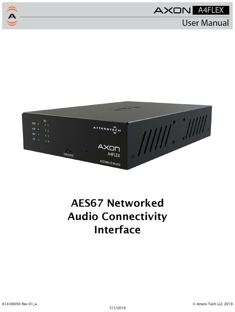
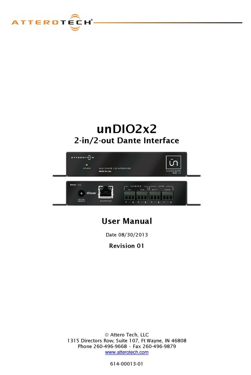
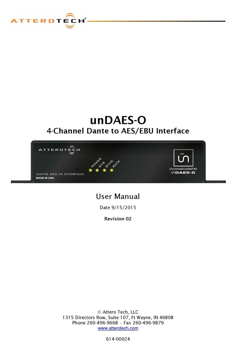
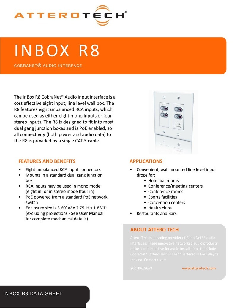
Other Attero Tech Accessories manuals

Attero Tech
Attero Tech Dante unDX2IO+ User manual

Attero Tech
Attero Tech SquawkBox User manual

Attero Tech
Attero Tech VoiceBox 4I/OP User manual

Attero Tech
Attero Tech unDIO2x2 User manual

Attero Tech
Attero Tech unDAES-O User manual

Attero Tech
Attero Tech AXON A4FLEX User manual

Attero Tech
Attero Tech COBRANET INBOX R8 User manual

Attero Tech
Attero Tech unAX4I AES67 User manual