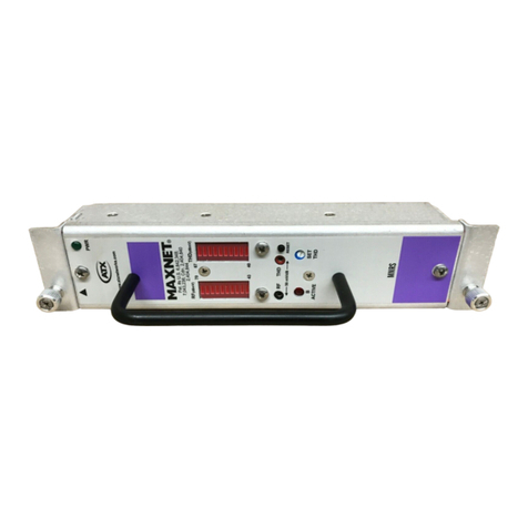
ATX ChromaFlex DMT24 User manual

HARDWARE INTERFACE MANUAL
ChromaFlex DMT24, DMT34 & DMT44 Multi-Wavelength
DWDM Direct Modulated Transmitter Module
ChromaFlex
www.atxnetworks.com
www.atxnetworks.com

Products or features contained herein may be covered by one or more U.S. or foreign patents. DOCSIS®and other non-ATX product and company names in this manual are the property of their
respective companies.
Although every effort has been taken to ensure the accuracy of this document it may be necessary, without notice, to make amendments or correct omissions.
Specications subject to change without notice.

ChromaFlex DMT24, DMT34 & DMT44 Multi-Wavelength DWDM Direct Modulated Transmitter Module – Hardware Interface Manual iii
TABLE OF CONTENTS
1 IMPORTANT SAFETY INSTRUCTIONS .................................... 1-1
1.1 Electric Shock Hazard ............................................. 1-1
1.2 Installation Site ................................................... 1-1
1.3 Installation Requirements ........................................... 1-1
1.4 Equipment Placement. . . . . . . . . . . . . . . . . . . . . . . . . . . . . . . . . . . . . . . . . . . . . . 1-1
1.5 Power Connections. . . . . . . . . . . . . . . . . . . . . . . . . . . . . . . . . . . . . . . . . . . . . . . . 1-2
1.5.1 Connection To AC Power Source .................................... 1-2
1.5.2 Connection To -48 VDC Power Source ................................ 1-2
1.6 Fuse Replacement ................................................ 1-2
1.7 Laser Safety ..................................................... 1-2
1.8 Laser Power & Warning Labels ...................................... 1-3
2 PRODUCT INTRODUCTION ............................................. 2-1
3 UNPACKING & INSPECTING A NEW UNIT ................................. 3-1
3.1 What To Do About Physical Damage .................................. 3-1
3.2 What To Do About Concealed Damage ................................ 3-1
3.3 How To Return Equipment .......................................... 3-1
4 SPECIFICATIONS...................................................... 4-1
5 BLOCK DIAGRAM & OPERATION ........................................ 5-1
6 FRONT PANEL ........................................................ 6-1
6.1 Front Panel Illustration ............................................. 6-1
6.2 Table of Front Panel Features ....................................... 6-1
6.3 Alarm Status Indicators............................................. 6-1
7 MODULE INSTALLATION ............................................... 7-1
8 MODULE CONNECTIONS ............................................... 8-1
8.1 RF Connections .................................................. 8-1
8.2 Optical Connections ............................................... 8-2
9 MODULE SET-UP ...................................................... 9-1
9.1 Setting RF Input Levels ............................................ 9-1
9.1.1 All QAM Channels ................................................ 9-1
9.1.2 Mix of Analog & QAM Channels ..................................... 9-1
9.2 Conguring The DMTx4 Transmitter Module ............................ 9-1
9.2.1 AGC Mode (Hand-held Display) ...................................... 9-2
9.2.2 MGC Mode (Hand-held Display)...................................... 9-3
9.3 Setting Transmitter Fiber Length ..................................... 9-4
10 TROUBLESHOOTING THE DMTX4....................................... 10-1
11. SERVICE & SUPPORT................................................. 11-1
11.1 Contact ATX Networks .............................................11-1
11.2 Warranty Information ..............................................11-1

iv ChromaFlex DMT24, DMT34 & DMT44 Multi-Wavelength DWDM Direct Modulated Transmitter Module – Hardware Interface Manual
This page intentionally left blank.

IMPORTANT SAFETY INSTRUCTIONS
ChromaFlex DMT24, DMT34 & DMT44 Multi-Wavelength DWDM Direct Modulated Transmitter Module – Hardware Interface Manual 1-1
IMPORTANT SAFETY INSTRUCTIONS
1. Important Safety Instructions
• Carefully read all safety and operating instructions contained in this user guide before operating this equipment, and
retain them for future reference.
• Follow all installation and operating instructions. Pay attention to all warnings and cautions in the manual as well as
those that are af xed to this equipment.
1.1 Electric Shock Hazard
This equipment meets applicable safety standards.
WARNING: To reduce risk of electric shock, perform only the instructions that are included in the
operating instructions. Refer all servicing to qualifi ed service personnel only.
Adhere to the following safety warnings and guidelines:
• Dangerous Voltages
◦ Only quali ed service personnel are allowed to perform equipment installation or replacement.
◦Disconnect power before servicing the unit.
◦ Only quali ed service personnel are allowed to remove chassis covers and access only eld replaceable
pluggable accessories.
• Grounding
◦Do not violate the protective grounding by using extension cables, power cables, or other devices on
the mains power without a protective ground conductor.
◦If this equipment is equipped with an external grounding terminal, attach one end of an 18-gauge
wire (or larger) to the grounding terminal; then, attach the other end of the wire to a ground, such as a
grounded equipment rack.
1.2 Installation Site
When selecting the installation site, comply with the following:
• Maintain a Protective Ground - The protective ground lead of the building’s electrical installation should comply with
national and local electrical and safety requirements.
• Environmental Condition - The installation site should be dry, clean, and ventilated. Do not use this equipment where
it could be at risk of contact with water. Ensure that this equipment is operated in an environment that meets the
requirements as stated in this equipment’s environmental speci cations.
1.3 Installation Requirements
WARNING: Allow only qualifi ed service personnel to install this equipment. The installation must
conform to all local codes and regulations.
1.4 Equipment Placement
WARNING: Avoid personal injury and damage to this equipment. An unstable mounting surface
may cause this equipment to fall.
• Install this equipment in a restricted access location.
• Place this equipment close enough to a mains AC outlet to accommodate the length of this equipment’s power cord.
• Route all power cords so that people cannot walk on, place objects on, or lean objects against them.
• Make sure the mounting surface or rack is stable and can support the size and weight of this equipment.
CHAPTER 1:

IMPORTANT SAFETY INSTRUCTIONS
1-2 ChromaFlex DMT24, DMT34 & DMT44 Multi-Wavelength DWDM Direct Modulated Transmitter Module – Hardware Interface Manual
• Make sure that the rack is placed on a stable surface. If the rack has stabilizing devices, install these stabilizing
devices before mounting any equipment in the rack. The mounting surface or rack should be appropriately anchored
according to manufacturer’s speci cations.
• Ensure this equipment is securely fastened to the mounting surface or rack to protect against damage.
• This equipment has openings for ventilation to protect it from overheating. To ensure equipment reliability and safe
operation, do not block or cover any of the ventilation openings.
WARNING: Avoid personal injury and damage to this equipment. Mounting this equipment in the
rack should be such that a hazardous condition is not caused due to uneven mechanical loading.
CAUTION: Installation of this equipment in a rack should be such that the amount of airfl ow
required for safe operation of this equipment is not compromised.
1.5 Power Connections
1.5.1 Connection To AC Power Source
Important: If this equipment is a Class I equipment, it must be grounded.
• Connect this equipment only to the power sources that are identi ed on the equipment-rating label.
• Overcurrent protection breakers or fuses must be sized appropriately for the total current rating of the modules and
accessories contained within a system chassis or multiple chassis that are connected to a common mains circuit.
• This equipment may have two power sources. Be sure to disconnect all power sources before working on this
equipment.
• If this equipment does not have a main power switch, the power cord connector serves as the disconnect device.
1.5.2 Connection To -48 VDC Power Source
• Use at least #16 AWG wire for all DC power wiring.
• Overcurrent protection breakers or fuses must be sized appropriately for the total current rating of the modules and
accessories contained within a system chassis.
• Follow the recommended practices of the DC power system manufacturer.
CAUTION: Consider the connection of this equipment to the supply circuit and the effect that
overloading of circuits might have on overcurrent protection and supply wiring.
1.6 Fuse Replacement
To replace a fuse, comply with the following:
• Disconnect the power before changing fuses.
• Identify and clear the condition that caused the original fuse failure.
• Always use a fuse of the correct type and rating. The correct type and rating are indicated on this equipment.
1.7 Laser Safety
This equipment may contain or be connected to an infrared laser source that transmits intensity-modulated light and emits
invisible radiation.
CHAPTER 1:

IMPORTANT SAFETY INSTRUCTIONS
ChromaFlex DMT24, DMT34 & DMT44 Multi-Wavelength DWDM Direct Modulated Transmitter Module – Hardware Interface Manual 1-3
WARNING: Avoid Personal Injury. The laser light source on this equipment or the fi ber cables
connected to this equipment emit invisible laser radiation. Avoid direct exposure to the laser light
source.
Viewing the laser output (if a transmitter) or fi ber cable with optical instruments may pose an eye
hazard.
This equipment may only be installed, operated and serviced by authorized personnel trained in
the safe handling and operation of fi ber optic cables and laser sources.
• Do not apply power to this equipment if the ber is unmated or unterminated.
• Do not look into an activated ber with optical instruments such as magni ers, or microscopes.
1.8 Laser Power & Warning Labels
This equipment may contain or be connected to other equipment containing Class 1M laser sources. The following labels
adhered to each product will indicate the type of laser source utilized along with general laser radiation labels.
CHAPTER 1:

IMPORTANT SAFETY INSTRUCTIONS
1-4 ChromaFlex DMT24, DMT34 & DMT44 Multi-Wavelength DWDM Direct Modulated Transmitter Module – Hardware Interface Manual
CHAPTER 2:
This page intentionally left blank.

PRODUCT INTRODUCTION
ChromaFlex DMT24, DMT34 & DMT44 Multi-Wavelength DWDM Direct Modulated Transmitter Module – Hardware Interface Manual 2-1
PRODUCT INTRODUCTION
2. Product Introduction
These are directly modulated C-Band DWDM downstream transmitter modules supporting up to 1.2 GHz for full DOCSIS®
3.1 spectrum. LC/APC front ber launch with or without internal multiplexing of outputs. Also includes front female F-port test
point with selection switch to locally monitor any individual laser input.
DMT24 has two separate lasers with one common RF input port (broadcast) and one unique (narrowcast) port per laser. For
a total of three RF inputs at rear of chassis.
DMT34 has three separate lasers with one common RF input port (broadcast) and one unique (narrowcast) port per laser.
For a total of four RF inputs at rear of chassis.
DMT44 has four separate lasers with one unique (narrowcast) port per laser. For a total of four RF inputs at rear of chassis.
Any Broadcast/Narrowcast combining is done externally if needed.
CHAPTER 2:

PRODUCT INTRODUCTION
2-2 ChromaFlex DMT24, DMT34 & DMT44 Multi-Wavelength DWDM Direct Modulated Transmitter Module – Hardware Interface Manual
This page intentionally left blank.
CHAPTER 2:

UNPACKING & INSPECTING A NEW UNIT
ChromaFlex DMT24, DMT34 & DMT44 Multi-Wavelength DWDM Direct Modulated Transmitter Module – Hardware Interface Manual 3-1
UNPACKING & INSPECTING A NEW UNIT
3. Unpacking & Inspecting a New Unit
Before shipment, ATX inspects and packs all the essential items carefully. Nevertheless, damage may occur during
shipment. The carrier assumes full responsibility for a safe delivery of the equipment.
Inspect the package for any physical damage.
1. Open the package.
2. Remove any packing material.
3. Inspect the unit for any physical damage.
4. Shake the unit with care, paying attention to any rattling loose parts that may suggest a concealed damage (some
noise due to moving cables is normal).
5. Check for any missing accessories.
When any damage is noticed to the merchandise, please notify customer service (see Service & Support section) and le a
claim with the carrier as noted below.
3.1 What To Do About Physical Damage
Record any evidence of physical damage or loss on the freight bill or receipt and have the carrier’s agent sign it. If you fail
to do so, the carrier may refuse to honor the damage claim. The carrier will supply you with any forms required to le such a
claim.
3.2 What To Do About Concealed Damage
Damage which is not apparent until the unit has been unpacked is considered concealed damage. The contents may have
been damaged due to rough handling even if there is no external evidence. If you should notice damage upon unpacking the
unit you should make a written request for inspection by the carrier’s agent within 10 days of the delivery date. Afterwards
le a claim with the carrier.
3.3 How To Return Equipment
Call customer service (see Service & Support section) for a Return Materials Authorization (RMA) number. You will need the
unit’s serial number, description of the problem, and some shipping information. We must receive the unit within thirty (30)
days from the date a RMA number is issued. If for any reason, you want to ship the unit 30 days after the RMA number has
been issued, you must obtain a new RMA number by calling customer service. Units received without an RMA number or
one with an expired RMA number will not be accepted by our receiving department.
CHAPTER 3:

UNPACKING & INSPECTING A NEW UNIT
3-2 ChromaFlex DMT24, DMT34 & DMT44 Multi-Wavelength DWDM Direct Modulated Transmitter Module – Hardware Interface Manual
CHAPTER 3:
This page intentionally left blank.

SPECIFICATIONS
ChromaFlex DMT24, DMT34 & DMT44 Multi-Wavelength DWDM Direct Modulated Transmitter Module – Hardware Interface Manual 4-1
SPECIFICATIONS
4. Specications
See ChromaFlex DMT24, DMT34 & DMT44 DWDM Transmitter Specs & Ordering Info pdf at atxnetworks.com
CHAPTER 4:

SPECIFICATIONS
4-2 ChromaFlex DMT24, DMT34 & DMT44 Multi-Wavelength DWDM Direct Modulated Transmitter Module – Hardware Interface Manual
CHAPTER 4:
This page intentionally left blank.

BLOCK DIAGRAM & OPERATION
ChromaFlex DMT24, DMT34 & DMT44 Multi-Wavelength DWDM Direct Modulated Transmitter Module – Hardware Interface Manual 5-1
BLOCK DIAGRAM & OPERATION
5. Block Diagram & Operation
The following block diagrams depict the RF and optical signal ow through the DMT24, DMT34 and DMT44 transmitter
modules:
BC
Input
(*-4)
NC1
(*-1)
NC2
(*-2)
Splitter
Variable
Attenuator
Variable
Attenuator
Front Panel
Test Point - 10 dB
OUT 1
OUT 2
DMT24
ITU*
ITU*
RF Det.
RF Det.
Opt. Mux
* = card
number (1..8)
Figure 1: ChromaFlex DMT24 Transmitter Module Block Diagram
Figure 2: ChromaFlex DMT34 Transmitter Module Block Diagram
BC
Input
(*-4)
NC1
(*-1)
NC2
(*-2)
NC3
(*-3)
Front Panel
Test Point - 10 dB
OUT 1
OUT 2
OUT 3
DMT34
ITU*
ITU*
ITU*
Opt. Mux
RF Det.
RF Det.
RF Det.
Variable
Attenuator
Variable
Attenuator
Variable
Attenuator
Splitter
* = card
number (1..8)
CHAPTER 5:

BLOCK DIAGRAM & OPERATION
5-2 ChromaFlex DMT24, DMT34 & DMT44 Multi-Wavelength DWDM Direct Modulated Transmitter Module – Hardware Interface Manual
Input 1
(*-1)
Input 2
(*-2)
Input 3
(*-3)
Input 4
(*-4)
Variable
Attenuator
Variable
Attenuator
Variable
Attenuator
Variable
Attenuator
RF Det.
RF Det.
RF Det.
RF Det.
ITU*
ITU*
ITU*
ITU*
Opt. Mux
Front Panel
Test Point - 10 dB
OUT 1
OUT 2
OUT 3
OUT 4
DMT44
* = card
number (1..8)
Figure 3: ChromaFlex DMT44 Transmitter Module Block Diagram
As seen in the block diagrams above and as described in Product Introduction, the DMT24 and DMT34 have internal RF
combining to merge a common broadcast RF input signal to each individual NC input. The DMT44 has no such combining
since all four rear F-ports are utilized for direct application to each laser segment in the quad module. After this initial
combining stage, all transmitter versions have the same functionality.
A directional coupler for each laser segment provides a sample of the full spectrum RF load applied to each laser to the
switchable female F-port on the front. This level is calibrated to be -10 dB relative to the input at the rear of the module,
regardless of AGC function of the module. The RF signal passes through a variable RF attenuator. The attenuator is
either automatically set through the feedback loop when operated in the AGC mode or may be set in the manual mode via
software interfaces. The signal is amplied and then passes through a directional coupler used to sample the RF signal for
remote monitoring and the AGC control loop back to the input variable attenuator. The through path is applied to a laser.
Fiber length adjustment for the laser is set through the software interfaces. The optical signal passes to each of the front
panel optical connectors. An internal multiplexer option is available in which case each wavelength is multiplexed internally
with the combined wavelengths connected to output port 1.
CHAPTER 5:

FRONT PANEL
ChromaFlex DMT24, DMT34 & DMT44 Multi-Wavelength DWDM Direct Modulated Transmitter Module – Hardware Interface Manual 6-1
FRONT PANEL
6. Front Panel
6.1 Front Panel Illustration
The following diagram and table depicts the features of the transmitter module front panel. The DMT44 module is shown for
reference. The DMT24 and DMT34 are labeled “NA” or “N” for the unused optical connector and RF test point selection.
6.2 Table of Front Panel Features
Module Extraction Levers Lever assist in removing the module from the chassis backplane
connector.
Module Retaining Screws Secures the module to the chassis.
Module Handle Utilized to insert and remove the module.
RF Test Point -10 dB sample of the RF input to the module. Relative to RF input at
rear of module.
RF Test Point Selector Switch Selects the RF test point for transmitter 1 to 4.
Optical Output LC/APC Connector (OUT) Optical output signal connection.
Transmitter Alarm LEDs Visual alarm status indicators for each of the four transmitters.
6.3 Alarm Status Indicators
LED Function Value
OPT One LED for Each Laser 1 through 4
Optical Output Power
Laser Temperature
Module Temperature
Green = Normal
Amber = Minor Temp Alarm or Opt
Power +/- 1dB
Red = Major Temp Alarm or Opt
Power +/- 2 dB
RF One LED for Each Laser 1 through 4
Monitors the RF Drive Level to Each
Laser
Green = Normal
Amber = Minor Alarm, RF Out of
Range +/- 2 dB
Red = Major Alarm, RF Out of
Range +/- 3 dB
For more information regarding alarm status and monitoring refer to the ChromaFlex Operation Manual.
CHAPTER 6:
Figure 4: Front Panel

FRONT PANEL
6-2 ChromaFlex DMT24, DMT34 & DMT44 Multi-Wavelength DWDM Direct Modulated Transmitter Module – Hardware Interface Manual
CHAPTER 6:
This page intentionally left blank.

MODULE INSTALLATION
ChromaFlex DMT24, DMT34 & DMT44 Multi-Wavelength DWDM Direct Modulated Transmitter Module – Hardware Interface Manual 7-1
MODULE INSTALLATION
7. Module Installation
The DMTx4 (x=2, 3 or 4) transmitter module occupies a single ChromaFlex chassis module slot. The modules may be
inserted or removed while the chassis is powered without interrupting other operational modules in the chassis. The
following module installation procedures assume the chassis is installed and powered following the instructions in the
ChromaFlex Operation Manual.
1. Align the module into the desired slot opening in the ChromaFlex chassis.
2. Using the handle push the module into the slot with even pressure until the module is mated with the chassis mid-
plane connector.
3. Press the module extraction levers downward against the module face.
4. Tighten the two module retaining screws until snug in an even manner.
5. The module LEDs should now be lit with the four OPT LEDs green and the four RF LEDs red (DMT44) if RF has not
already been connected to the chassis rear panel RF connectors.
CHAPTER 7:

MODULE INSTALLATION
7-2 ChromaFlex DMT24, DMT34 & DMT44 Multi-Wavelength DWDM Direct Modulated Transmitter Module – Hardware Interface Manual
CHAPTER 7:
This page intentionally left blank.
This manual suits for next models
2
Table of contents
Other ATX Control Unit manuals
Popular Control Unit manuals by other brands

Renishaw
Renishaw SLM 250 Installation and operation

Honeywell
Honeywell Silent knight 5895XL Installation and operation guide

ABB
ABB AC500 PLC Hardware manual

Bristan
Bristan MT503CP Installation instructions and user guide

Kemper
Kemper 361 Installation and operating instructions

Hitachi
Hitachi CU-HD500 operating instructions