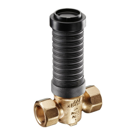
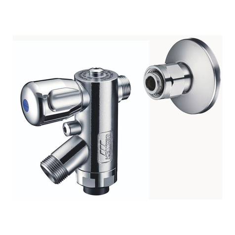
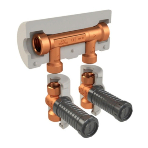
Kemper 361 User manual
Other Kemper Control Unit manuals
Kemper
Kemper KHS 686 04 User manual
Kemper
Kemper MULTI-FIX-PLUS 150 6G User manual
Kemper
Kemper FK-5 User manual
Kemper
Kemper ETA-THERM 130 User manual

Kemper
Kemper 619 01 User manual
Kemper
Kemper 689 04 025 User manual
Kemper
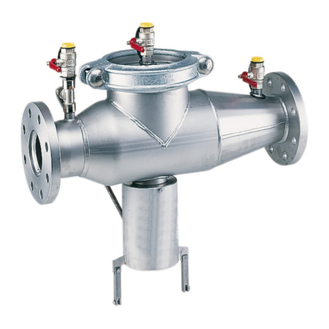
Kemper PROTECT RPZ User manual
Kemper
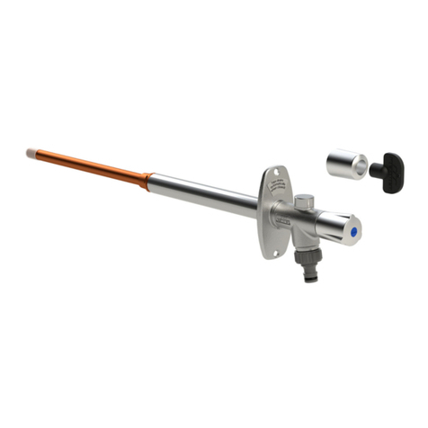
Kemper FROSTI User manual
Kemper
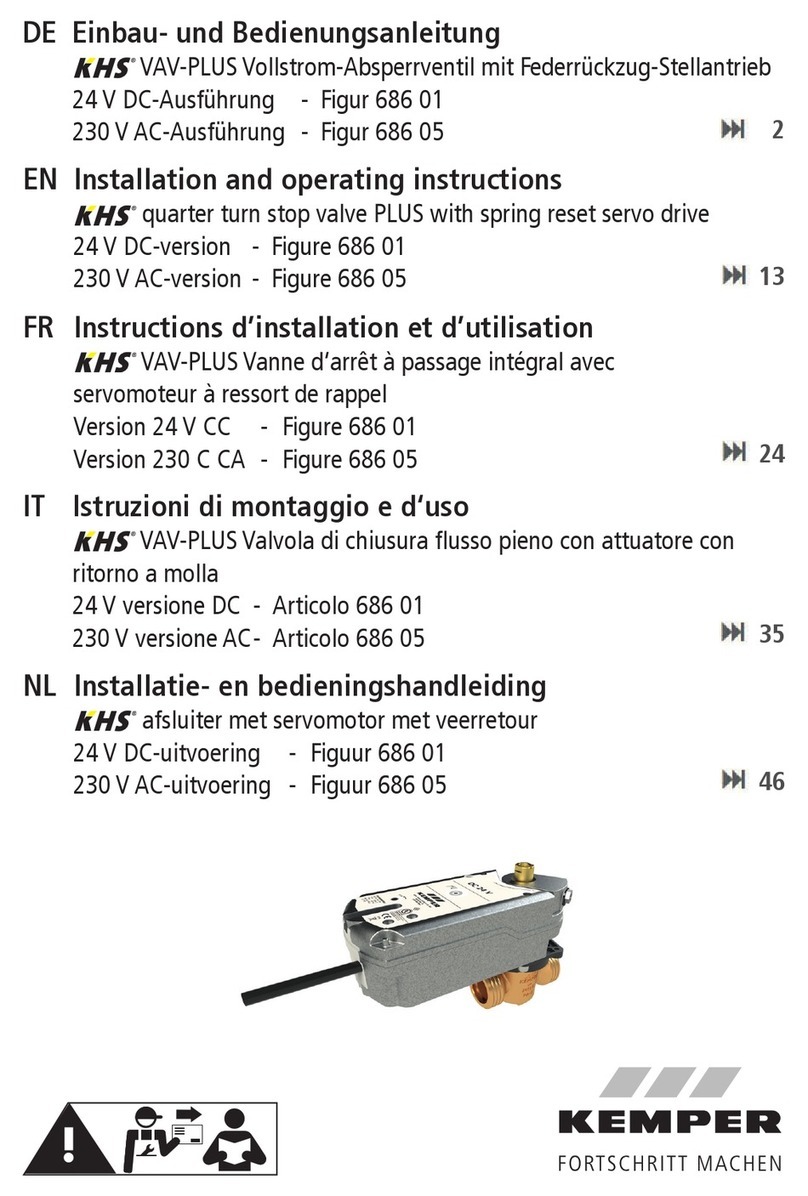
Kemper KHS VAV-PLUS User manual
Kemper
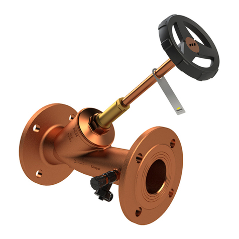
Kemper 137 02 User manual
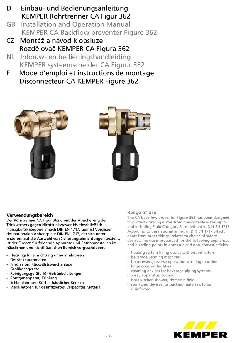
Kemper
Kemper CA 362 User manual
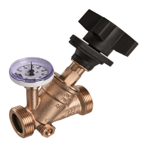
Kemper
Kemper Figure 150 6G User manual
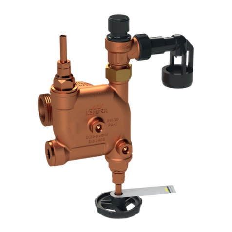
Kemper
Kemper 7140G02000 User manual
Kemper
Kemper 360 User manual
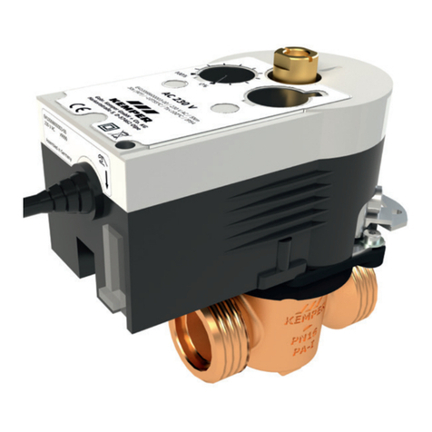
Kemper
Kemper kHS 686 00 User manual
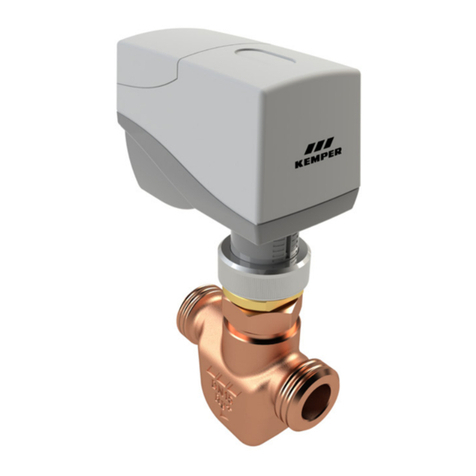
Kemper
Kemper KHS CoolFlow 615 0G User manual
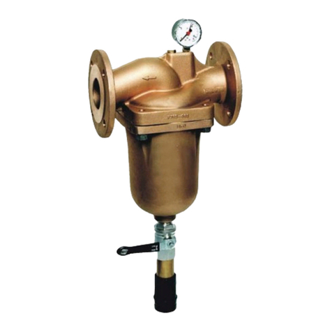
Kemper
Kemper Figure 708 User manual
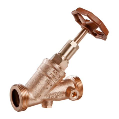
Kemper
Kemper 145 2G User manual
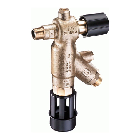
Kemper
Kemper FK-4 RPZ User manual
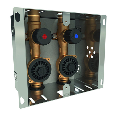
Kemper
Kemper DUO 870 07 User manual
Popular Control Unit manuals by other brands

Festo
Festo Compact Performance CP-FB6-E Brief description

Elo TouchSystems
Elo TouchSystems DMS-SA19P-EXTME Quick installation guide

JS Automation
JS Automation MPC3034A user manual

JAUDT
JAUDT SW GII 6406 Series Translation of the original operating instructions

Spektrum
Spektrum Air Module System manual

BOC Edwards
BOC Edwards Q Series instruction manual

KHADAS
KHADAS BT Magic quick start

Etherma
Etherma eNEXHO-IL Assembly and operating instructions

PMFoundations
PMFoundations Attenuverter Assembly guide

GEA
GEA VARIVENT Operating instruction

Walther Systemtechnik
Walther Systemtechnik VMS-05 Assembly instructions

Altronix
Altronix LINQ8PD Installation and programming manual
