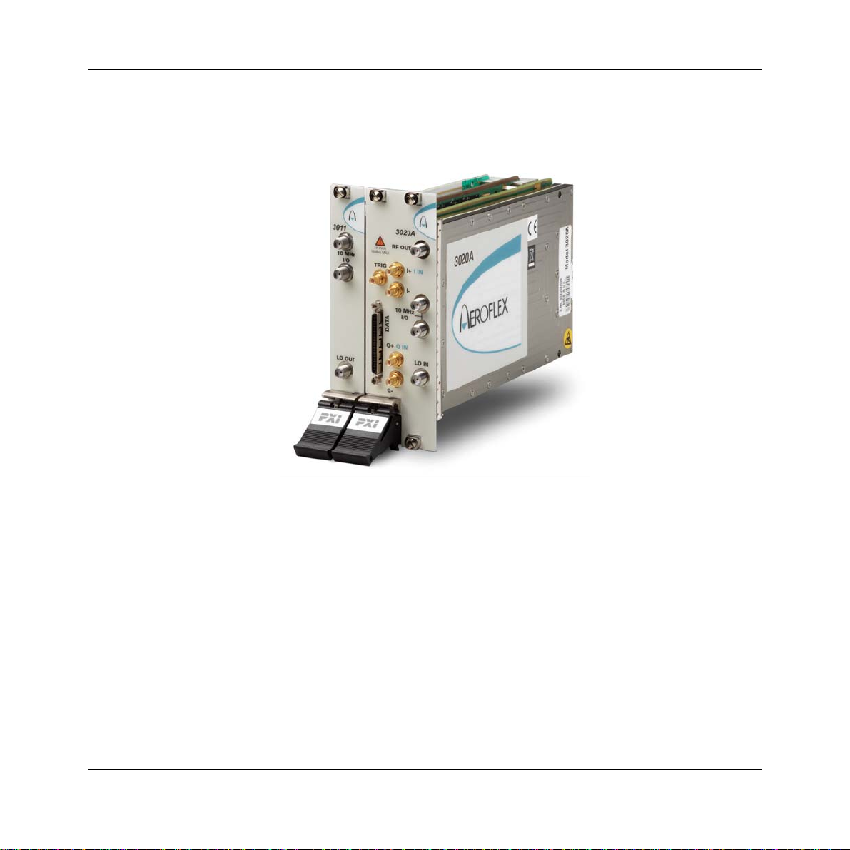
Aeroflex 3020A User manual

3020A Digital RF Signal Generator
PXI Module
Operating Manual
Document no. 46892/717
Issue 4
14 March 2007

PREFACE
About this manual
This manual applies to instruments with software issues of 2.0 and higher.
This manual explains how to set up and configure an Aeroflex 3020A digital RF signal
generator PXI module. Where necessary, it refers you to the appropriate installation
documents that are supplied with the module.
This manual provides information about how to configure the module as a stand-alone device.
However, one of the advantages of Aeroflex 3000 Series PXI modules is their ability to form
versatile test instruments, when used with other such modules and running 3000 Series
application software.
Getting Started with afSigGen (supplied on the CD-ROM that accompanies each module (see
Associated documentation)) explains how to set up and configure a 3020 Series RF signal
generator with a 3010 Series RF synthesizer module. Using the signal generator soft front
panel and/or dll or COM object supplied, the modules form an instrument that provides the
functionality and performance of an integrated, highly-specified signal generator, but with the
adaptability to satisfy a diverse range of test or measurement requirements.
© Aeroflex International Ltd. 2007
No part of this document may be reproduced or transmitted in any form
or by any means, electronic or mechanical, including photocopying,
or recorded by any information storage or retrieval system,
without permission in writing by Aeroflex International Ltd.
(hereafter referred to throughout the document as ‘Aeroflex’).

PREFACE
iii
Intended audience
Users who need accurately-generated signals in the VHF and UHF spectrum.
This manual is intended for first-time users, to provide familiarity with basic operation.
Programming is not covered in this document but is documented fully in the help files that
accompany the drivers and associated software on the CD-ROM.
Structure
Chapter 1 General information
Chapter 2 Installation
Chapter 3 Operation
Chapter 4 Brief technical description
Chapter 5 Acceptance testing

PREFACE
iv
Associated documentation
The following documentation covers specific aspects of this equipment:
PXI Modules CD-ROM Part no.
46886/028 Compilation containing soft front panels, drivers,
application software, data sheets, getting started
and operating manuals for this and other modules
in the 3000 Series.
3000 Series PXI
Modules Common
Installation Guide
Part no.
46882/663 Detailed information on installing modules into a
rack, external connections, powering up and
installing drivers.
3000 Series PXI
Modules Installation
Guide for Chassis
Part no.
46882/667 Explains how to set up a populated chassis ready
for use.
Getting Started with
afSigGen Part no.
46892/678 Setting up and using the signal generator
application for 3010 Series and 3020 Series
modules.
PXI Studio User Guide Part no:
46892/809 Setting up and using the universal PXI application
for system configuration and operation.

PREFACE
v
Preface
The PXI concept
VXI and GPIB systems meet the specific needs of instrumentation users but are often too
large and expensive for mainstream applications. PC-based instrumentation may cost less but
cannot meet the environmental and operational requirements of many systems.
PXI (PCI Extensions for Instrumentation) is based on CompactPCI, itself based on the PCI
standard. PCI was designed for desktop machines but CompactPCI was designed for
industrial applications, and features a rugged Eurocard format with easy insertion and
removal. PXI adds to the CompactPCI specification by defining system-level specifications
for timing, synchronization, cooling, environmental testing, and software. While PXI extends
CompactPCI, it also maintains complete interoperability so that you can use any CompactPCI-
compliant product in a PXI system and vice versa. PXI also makes use of Windows software,
VXI timing and triggering, and VXIplug&play instrument drivers to provide powerful and
affordable systems.
®is a registered trademark of Aeroflex International Inc. in the US
PXI™ is a registered trademark of the PXI Systems Alliance
Windows™, Windows XP™ and Windows NT™ are trademarks of Microsoft Corporation

PREFACE
vi
Abbreviations/acronyms
ACP(R) Adjacent Channel Power (Ratio)
ADC Analog-to-Digital Converter
ALC Automatic Level Control
AM Amplitude Modulation
ARB Arbitrary Waveform Generator
ATE Automatic Test Equipment
CW Continuous Wave
DAC Digital-to-Analog Converter
dB Decibels
dBc Decibels relative to the carrier level
dBm Decibels relative to 1 mW
EVM Error Vector Magnitude
FM Frequency Modulation
FPGA Field Programmable Gate Array
GND Ground
IQ In-phase/Quadrature
ISP In-System Programming
LO Local Oscillator
LSTB List Strobe
LVDS Low-Voltage Differential Signaling
PCI Peripheral Component Interconnect

PREFACE
vii
Pk-Pk Peak-to-Peak
PXI PCI eXtensions for Instrumentation
RF Radio Frequency
RMS Root Mean Square
SDRAM Synchronous Dynamic RAM
SFP Soft Front Panel
SMA SubMiniature version A (connector)
SMB SubMiniature version B (connector)
TDMA Time Division Multiple Access
TRIG Trigger
TTL Transistor-Transistor Logic
UUT Unit Under Test
VCO Voltage-Controlled Oscillator
VHDCI Very High Density Connector Interface
VSWR Voltage Standing-Wave Ratio
VXI VMEbus Extension for Instrumentation

1-1
Chapter 1 GENERAL INFORMATION
Introduction
Welcome to the operating manual for the 3020A Digital RF Signal Generator.
The 3020A Digital RF Signal Generator operates over a frequency range of 250 MHz to
2.7 GHz and a level range of +5 dBm to −120 dBm. The RF output may be continuous wave
(CW) or modulated. Modulation can be internal analog AM/FM, internal and external digital
IQ, or external vector (when Option 01 is fitted).

GENERAL INFORMATION
1-2
Internal digital IQ modulation is supported by a built-in dual-channel arbitrary waveform
generator (ARB). This ARB is compatible with waveforms designed or packaged using the
®software application. Differential baseband I and Q outputs from the ARB are
available as an option. External digital IQ modulation is supported via an LVDS data
interface. An external synthesizer provides a local oscillator input signal: the 3010 Series RF
Synthesizer is recommended. The two modules together occupy only three slots in a 3U PXI
chassis.
Applications
The 3020A is ideal for generating complex modulated waveforms for digital radio
communications test and measurement applications, satellite and terrestrial TV broadcasting,
military communications and WLAN. When the 3020A is used with other Aeroflex PXI RF
modules, complete RF test systems can be implemented. High RF accuracy, stability and
repeatability ensure consistent measurement results, helping to improve manufacturing yield.
Wide frequency coverage
The 3020A’s frequency range makes it ideal for multi-purpose applications in UHF radio
communications, especially important when testing multi-mode cellular terminals.
Low noise and frequency-agile
When used with a 3010 Series synthesizer, the 3020A provides the low noise and high
switching speed necessary for high-productivity RFIC testing or the stimulus to frequency-
hopping radios.
RF level accuracy and bursting
The 3020A maintains accurate RF output levels to typically ±0.3 dB, and can generate
modulated RF bursts to simulate TDMA signal characteristics.
IQ digital modulation
The 3020A provides high-quality digital modulation suitable for all common radio
communications applications, either from the internal ARB or from an external source via the
LVDS data connector.

GENERAL INFORMATION
1-3
Analog I &Q inputs and outputs (optional)
The 3020A can provide baseband I and Q output and CW RF output simultaneously.
Differential analog I and Q outputs from the ARB are provided, with control of differential
output level, DC bias and offset voltage.
IQ vector modulation
Analog I and Q inputs can be used to generate wideband vector modulation from external
analog I and Q sources such as test instruments and device outputs.
Arbitrary waveform generator (ARB)
The ARB can store 32 MSamples, either as a single long waveform or any number of smaller
waveforms up to the capacity limit of the sample memory. Waveforms transfer quickly
between the PXI controller and the ARB because of the wide bandwidth of the PCI backplane.
Playback times of more than 30 minutes are possible, longer if ARB sequencing is used.
ARB sequencing
ARB sequencing provides a method for extending the effective ARB sample memory as well
as providing a flexible way to compile test sequences. You can define up to 128 sequence
steps, each of which defines an ARB file from a selection of 64, and plays it a chosen number
of times before continuing on to the next file in the ARB sequence.
Triggering and synchronization
The 3020A provides flexible, configurable triggering facilities from inputs on the front panel
or the PXI backplane. Triggers can be used for addressed selection or stepped incrementing
of list mode. Triggers can generate power bursts and can be programmed into ARB
waveforms to provide trigger outputs for other instruments.
A configurable routing matrix provides flexibility in how you interconnect signals on the PXI
backplane, the LVDS and TTL front-panel inputs, and the module’s internal functions.
Predefined routing scenarios can be loaded, or new scenarios created to meet particular
requirements.

GENERAL INFORMATION
1-4
List mode
List mode enables very fast settling times for new signal configurations. In list mode, up to
128 internal hardware settings are pre-calculated and stored, providing fast switching of
frequency and level whilst maintaining RF output accuracy. List addresses are sourced
externally or from an internal counter driven by the test application controlling the 3020A.
Software
The 3020A is supplied with a VXI PNP driver and soft front panel for use as a standalone
module, and a signal generator soft front panel and dll or COM object for use with a 3010 or
3011 RF Synthesizer.
Refer to the guide Getting Started with afSigGen (part no. 46882/678), also available on the
PXI Modules CD-ROM part no. 46886/028.
®allows you to design your own, or system-specific, complex modulation files for
use with the 3020A’s ARB.
RF Investigator, also supplied with the module, is an application that provides combined
operation of all Aeroflex 3000 Series modules from a single user interface, especially useful
for acceptance testing.
PXI Studio, also supplied with the module, configures your PXI modules as logical
instruments that will eventually run analysis plugins to suit any modulation scheme.

GENERAL INFORMATION
1-5
Deliverable items
• 3020A RF Signal Generator PXI module
• PXI Modules CD-ROM (part no. 46886/028), containing soft front panels, drivers,
application software, data sheets and operating manuals for this and other modules in the
3000 Series
• 3000 Series PXI Modules Common Installation Guide, part no. 46882/663
• 3000 Series PXI Modules Installation Guide for Chassis, part no. 46882/667
• SMA connector cable, part no. 43138/421
• SMA connector saver, part no. 46885/224
Cleaning
Before commencing any cleaning, switch off the chassis and disconnect it from the supply.
You can wipe the front panel of the module using a soft cloth moistened in water, taking care
not to wet the connectors. Do not use aerosol or liquid solvent cleaners.
Putting into storage
If you put the module into storage, ensure that the following conditions are not exceeded:
Temperature range: −20 to +70°C (−4 to +158°F)
Humidity: 5 to 93%, non-condensing

2-1
Chapter 2 INSTALLATION
WARNING
Initial visual inspection
Refer to the 3000 Series Common Installation Guide 46882/663.
Handling precautions
Refer to the 3000 Series Common Installation Guide 46882/663.
Hardware installation
Installing the module into the PXI chassis
Refer to the 3000 Series Common Installation Guide 46882/663 and Installation Guide for
Chassis 46882/667.

INSTALLATION
2-2
Coaxial connector torque settings and
maintenance
Torque settings
Use a torque spanner to tighten SMA connectors together, in order to ensure consistent
matching and to avoid mechanical stress. Torque settings for connectors are:
0.56 Nm test torque (development use, semi-permanent installations)
1 Nm final torque (permanent installations)
Never use pliers to tighten connectors.
Maintenance
Clean connectors regularly, using a cotton bud dipped in isopropyl alcohol. Wipe within the
connector cavity, then use a dry cotton bud to finish off. Check for any deposits.
Do not use other cleaners, as they can cause damage to the plastic insulators within the
connectors.
When joining connectors, try to minimize relative rotation between the mating parts as you
tighten the nut
Cap unused connectors.

3-1
Chapter 3 OPERATION
Front-panel connectors
1 RF OUT RF output, −120 to +5 dBm, 250 MHz to
2.7 GHz. SMA socket, 50 Ω.
2 I IN, I+ , I−
Option 01
only
Analog I input (I IN), selectable
50Ω/100 kΩ. Analog I output (I+ and I−),
50Ωsingle-ended, 100 Ωdifferential. SMB
sockets.
3 10 MHz I/O Two SMA I/O sockets in parallel.
Input
External frequency standard input for
sampling clock. 0.4 to 4 V pk-pk into 50 Ω.
Output
Link-through from input.
4 Q IN, Q+ ,
Q−
Option 01
only.
Analog Q input (Q IN), selectable
50Ω/100 kΩ. Analog Q output (Q+ and Q−),
50Ωsingle-ended, 100 Ωdifferential. SMB
sockets, 50 Ω.
5 LO IN 1.5 to 3 GHz, nominally 0 dBm. SMA
socket, 50 Ω.
6 DATA 68-way VHDCI connector for LVDS data
I/O, 14-bit IQ digital data input.
See Appendix B for details.
7 TRIG TTL +ve or –ve edge. SMB socket, 50 Ω.
C5949
6
7
1
4
5
3
2
LO IN
Q-
Q+
I-
TRIG
QIN
I+ IIN
10 MHz
I/O
3020A
REV PWR
20dBm MAX
DATA
RF OUT
Fig. 3-1 3020A front panel
Maximum safe power
Reverse power handling: not to exceed +20 dBm

OPERATION
3-2
Soft front panel (af3020_sfp)
The soft front panel provides a graphical interface for operating the module. It is intended for
testing and diagnosing, for demonstration and training, and for basic operation of the module.
It represents most of the functions available in the instrument driver. It is not however a
comprehensive application suitable for measurements; for this, use the afSigGen DLL or
afSigGen COM object.
Installation
The soft front panel is installed during the driver installation process (refer to the 3000 Series
PXI Modules Common Installation Guide, part no. 46882/663).
Open the AF3020_sfp.exe file: this is in the C:\VXIPNP|WinNT\af3020\ directory on a
Windows NT machine, for example. It is also accessible from the Windows Start menu under
Programs\Aeroflex\PXI Module Front Panels\AF3020 Front Panel. The soft front panel,
similar to that in Fig. 3-2, is displayed.
Detailed help information
Soft front panel controls are all available as driver export functions unless noted otherwise,
and are documented in the help files (page 3-25). This operating manual provides an
overview of the facilities that the module provides and summarizes its operation; however,
refer to the help files for detailed descriptions of functions, together with their parameter lists
and return values.

OPERATION
3-3
C6115
Triggering
Boot
Sample rate
ARB handling
Menu bar
RF settings
Fig. 3-2 3020A soft front panel

3-4
Soft front panel controls
Menu bar
File
Click Exit to close the application.
Settings
Load and Saveallow you to load and save soft front panel configurations from and to your
preferred locations. If you did not change the default location when installing the software, it
is C:\VXIPNP\WinNT\af3020\settings, and configurations are saved as .ini files.
You can edit, copy and paste settings files as required; for example, you may want to
save only a new routing setup without changing other parameters. Edit the saved .ini
file using a text editor (for example, Notepad) to remove unwanted parameters. Ensure
only that you do not delete the General (VendorID, DeviceID) and Version
(Major/Minor) parameters. Save the changed file. When the settings file is next loaded,
the configuration of the soft front panel changes to match the parameters remaining in
the settings file, leaving all other settings unchanged.
Directories lets you choose the locations for your front-panel configuration settings, ARB
files and catalogs, synthesizer plugin DLLs and calibration files.
Synthesizer plugins must support a VXIPNP (VISA) RF synthesizer resource capable of
1.5 GHz to 3 GHz. Certain exported functions are also required: refer to online help for
details.
LVDS: select the Data Size (14-bit or padded to 16-bit) and Sign (unsigned/signed) to match
different data types.

MENU BAR ON SOFT FRONT PANEL
3-5
Routing Scenarios allows you to select a predefined routing matrix connection. A tick
against the scenario’s title shows that it is selected.
If you select a scenario, and then a second, any connected or enabled outputs common to both
scenarios are overwritten by the second. Enabled outputs in the first scenario that do not
appear in the second also remain active. If the second scenario changes any outputs that were
used by the first, the first scenario is invalidated. This process extends to further scenarios.

MENU BAR ON SOFT FRONT PANEL
3-6
Routing Matrix displays a matrix that provides interconnection between input and output
signals on the PXI backplane bus, the DATA connector and the 3020A’s internal circuitry, as
shown diagrammatically in Fig. 3-3. This provides great flexibility in how you route signals
between modules.
DATA
INTERNAL
FUNCTIONS
3020A PXI MODULE
PXI BACKPLANE BUS
C5953
PXI Star
PXI LBL[0]–[12]
PXI Trig[0]–[7]
ARB Trigger
ARB Marker1–4
RF Off Ext
Mod Off Ext
Freeze Ext
RF Blank
SEQ Start
List Strobe In
List Strobe Out
GND
LVDS Marker 1–4
LVDS Aux[0]–[4]
LVDS Spare 0–2
TRIG
ROUTING MATRIX
Fig. 3-3 Routing matrix in 3020A
This manual suits for next models
1
Table of contents
Other Aeroflex Control Unit manuals

Aeroflex
Aeroflex SmartStep 8310 User manual

Aeroflex
Aeroflex 3065 User manual

Aeroflex
Aeroflex 3020 Series User manual

Aeroflex
Aeroflex 3035 User manual

Aeroflex
Aeroflex 3010 Series User manual

Aeroflex
Aeroflex 3000 Series User manual

Aeroflex
Aeroflex 3035C User manual

Aeroflex
Aeroflex 3060 Series User manual
Popular Control Unit manuals by other brands

Tews Technologies
Tews Technologies TIP866-TM-10 user manual

Eaton
Eaton ELC-MC01 instruction sheet

Agilent Technologies
Agilent Technologies 54753A Programmer's reference

Renson
Renson Endura Twist user manual

Clack
Clack WS1TC Series Operation and instruction manual

Textron
Textron GREENLEE PVA0021 instruction manual