ATX Condential & Proprietary
PREFACE
GENERAL DESCRIPTION
1. General Description
The SignalOn Series is a modular system allowing for combining and splitting of the headend signals in a CATV system.
The system is designed to accommodate efcient cable management, EMI shielding, and ease of use. All of these help to
facilitate easy reconguration and high performance within a dynamic headend environment.
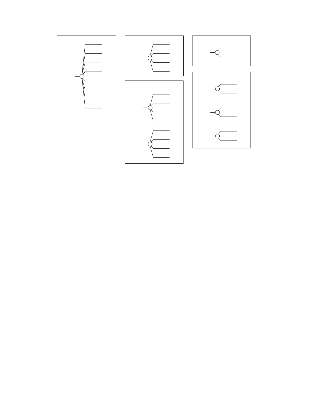
1.1. Splitters/Combiners
Splitters and combiners are modular devices designed to slide into a chassis and secured by thumbscrews. They are available
in a plain style or pads-and-monitor style. Modules have BNC or F type connectors for customer connections. A variety of
splitters and combiners may be installed in each chassis.
1.1.1. Pads-and-Monitor Style Splitters and Combiners
Splitters and combiners with monitor ports are available with either 0 dB or 6 dB default attenuation. Module attenuation
default value, module type, and monitor information is noted on the blue label located at the top of each module. For example,
the label shown in Figure 1 indicates that this is a combiner module; it is a 3-up, 2-to-1, with on-board default attenuation of
0 dB. It also has three monitor ports all 20 dB down from the common port. Attenuation pads may be installed to change the
attenuation from 0 to 20 dB.
Pad contacts are make-before-break (MBB). This means that without an attenuator in place, the make-before-break contact
is closed, providing the on-board default attenuation value to the circuit. When an attenuator pad is inserted, the make-
before-break contacts open, routing the signal through the attenuator, replacing the on-board default attenuation value of
0 dB or 6 dB with the value of the attenuator pad. A monitor port is included on the padded modules, providing a –20 dB
reference signal with high isolation between the monitor and input ports. See schematic on each module for details.
1.1.2. Pads
The attenuation pads used in these modules are available with insertion loss values of 0 to 20 dB in 1 dB steps and are for
use in the frequency range: 5 MHz to 1,000 MHz.
1.1.2.1. Changing Attenuation Pads
When make-before-break modules are used attentuation pads may be changed without interrupting the signal. Attenuation
pad value is stamped on the front of each pad. Determine new attentuation value required. Remove the existing attentuation
pad and install a new pad with the appropriate value as follows:
1. Remove protective cover from the front of the module by loosening the thumbscrew.
2. Grasp the pad to be changed and pull it straight out of the module.
3. Position new pad in the module and press straight into place.
4. Replace protective cover on the front of the module and hand-tighten the thumbscrew.
SignalOn®Series – RF Passive Modules - Installation & Operation Manual 1-1
CHAPTER 1: GENERAL DESCRIPTION
Figure #1: Module Label
3X[2:1]
DEFLT
0dB
20dB
20dB
20dB