AU SAE J1939 User manual
Au Group Electronics Au SAE J1939 Simulator Gen II 1.00A User Manual Rev. G
1
Au SAE J1939 Simulator Gen II 1.00A
User Manual
Rev. G
Au Group Electronics
May 2019
All Copyrights are reserved by Au Group Electronics. 2007 - 2019
This document can NOT be freely distributed without written approval from Au Group Electronics

Au Group Electronics Au SAE J1939 Simulator Gen II 1.00A User Manual Rev. G
Website: www.AuElectronics.com Support: Support@AuElectronics.com
2/36
Table of Contents
Table of Contents ........................................................................................................................................... 2
Chapter 1 - Introduction ................................................................................................................................. 3
1.1. Typical SAE J1939-15 Network Topology with Au SAE J1939 Simulator ............................. 3
1.2. Major Hardware Features.......................................................................................................... 3
1.3. Major Operating Features.......................................................................................................... 6
1.4. Eight Editions of Au SAE J1939 Simulators ............................................................................ 6
1.5. Basic Functions of Each Edition ............................................................................................... 6
1.6. License /Firmware Upgrade and Annual Support Service ........................................................ 7
Chapter 2 - Supported SAE J1939 Parameters............................................................................................... 8
2.1. Value Package editions.............................................................................................................. 8
2.2. Engine Basic editions ................................................................................................................ 8
2.3. Engine Premium editions .......................................................................................................... 8
2.4. Vehicle Platinum editions.......................................................................................................... 8
Chapter 3 - Operating Instructions ................................................................................................................. 9
3.1. Power On ................................................................................................................................... 9
3.2. Operating Mode (Static/Dynamic) ............................................................................................ 9
3.3. Push Button Function ................................................................................................................ 9
3.4. LED Indicator Status ............................................................................................................... 10
Chapter 4 - Au J1939 Simulator Remote Terminal GUI.............................................................................. 13
4.1. Control Panel – Step 1: Connect to J1939 Simulator .............................................................. 15
4.2. Control Panel – Step 2: Remote control the J1939 Simulator................................................. 16
4.3. Display Panel – Engine info and Warning Lamps .................................................................. 16
4.4. Display Panel – ABS info and Warning Lamps...................................................................... 16
4.5. Display Panel – Transmission info and Warning Lamps ........................................................ 17
4.6. Display Panel – Value Package Parameters ............................................................................ 17
4.7. Display Panel – Engine Basic Parameters............................................................................... 17
4.8. Display Panel – Engine DM1 .................................................................................................. 17
4.9. Display Panel – Engine DM2 .................................................................................................. 19
4.10. Display Panel – Engine Configuration .................................................................................... 20
4.11. Display Panel – ABS DM1...................................................................................................... 20
4.12. Display Panel – Transmission DM1........................................................................................ 20
Chapter 5 - Data Configuration .................................................................................................................... 21
Appendix A - Remote Terminal GUI Installation Guide ............................................................................. 28
Appendix B - CAN Baud Rate Configuration.............................................................................................. 30
Appendix C - License Management Toolset ................................................................................................ 31
Appendix D - Au PIC Serial Bootloader Application Note ......................................................................... 35

Au Group Electronics Au SAE J1939 Simulator Gen II 1.00A User Manual Rev. G
Website: www.AuElectronics.com Support: Support@AuElectronics.com
3/36
Chapter 1 - Introduction
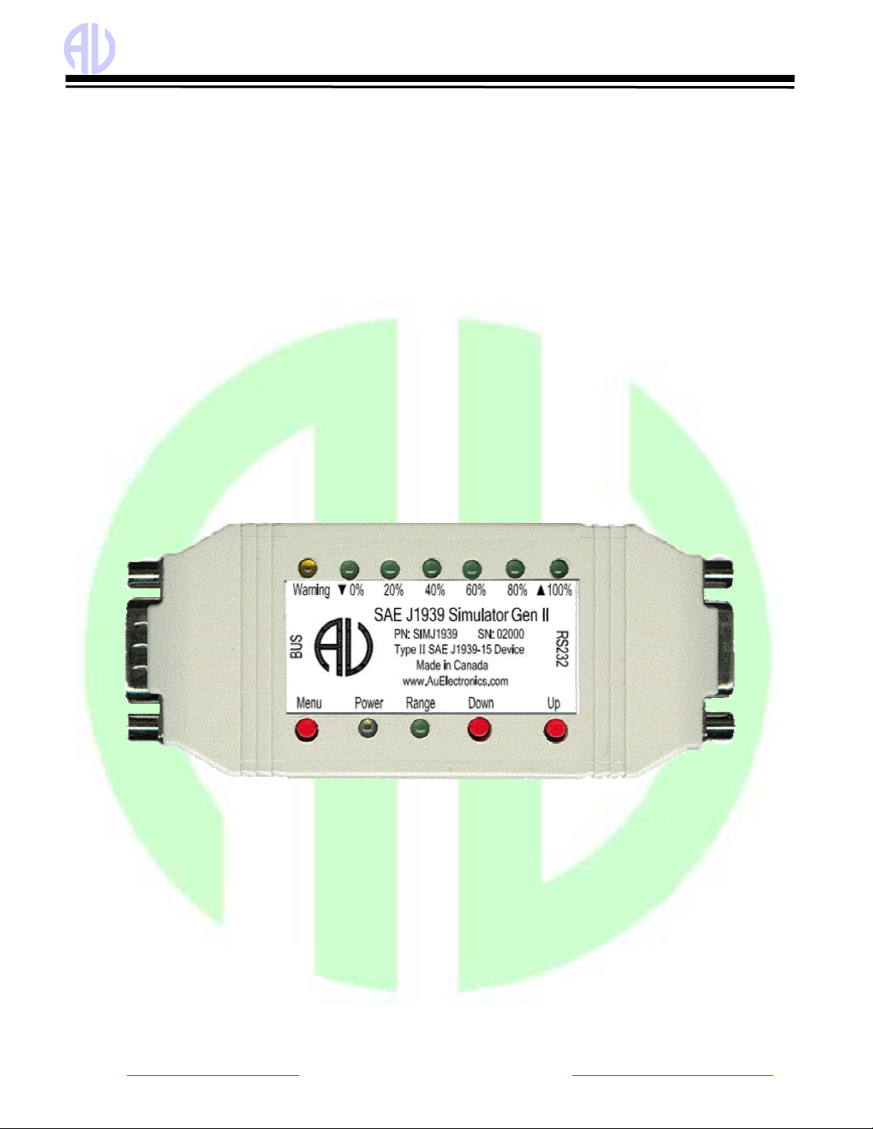
Au SAE J1939 Simulator Gen II 1.00A, a family of well designed
devices, is capable of simulating majority of SAE J1939 signals on a
SAE J1939 network (Figure 1-1).
1.1. Typical SAE J1939-15 Network Topology with Au SAE
J1939 Simulator
A typical SAE J1939-15 network topology with Au SAE J1939 Simulator is illustrated in Figure 1-2.
Figure 1-2 Typical SAE J1939-15 network topology with Au SAE J1939 Simulators
1.2.Major Hardware Features
•SAE J1939-15 Type II ECU: contain an internal 120 ohm load resistor for easy network setup
•TVS (Transient Voltage Suppressor) protection on CAN bus
•Compact size: 4-1/8" L X 1-3/4"W X 7/8”H
•Enclosure color: Black or PC white
•Operating temperature: -4 ˚F to 185 ˚F (-20 ˚C to 85 ˚C)
•Power supply: +12V DC nominal, 250mA max
•9 LED indicators: Power, Range, Warning, ▼0%, 20%, 40%, 60%, 80%,▲100%
•1 buzzer
•3 push buttons: simulated SAE J1939 signals can be adjusted by 3 push buttons: Menu, Down, Up
•1 DB9 Male "BUS" Interface: for power supply and CAN/J1939 network connection (Figure 1-3)
•1 RS232 interface: for in field firmware update, license management, and computer remote control
(for Plus editions only).
Figure 1 - 1 Au J1939 Simulator Gen II

Au Group Electronics Au SAE J1939 Simulator Gen II 1.00A User Manual Rev. G
Website: www.AuElectronics.com Support: Support@AuElectronics.com
4/36
Figure 1 - 3 Pin-out for BUS side DB9 male connector
Figure 1 - 4 Pin-out for RS232 side DB9 female connector
Au J1939 Simulator plus edition can be connected to a PC either through RS232 port or USB port.
Au J1939 Simulator plus edition can be connected to a PC through RS232 serial port using RS232 serial extension cable (part #
CBL-RS232-01), as shown in Figure 1 - 5.
Figure 1-5 Connection of Au J1939 Simulator (Gen II) plus editions to PC with RS232 port
Au J1939 Simulator plus edition can be connected to a PC through USB port using USB to RS232 serial convert cable (part #
CBL-USB-232), as shown in Figure 1 - 6.
Figure 1-6 Connection of Au J1939 Simulator (Gen II) plus editions to PC with USB port
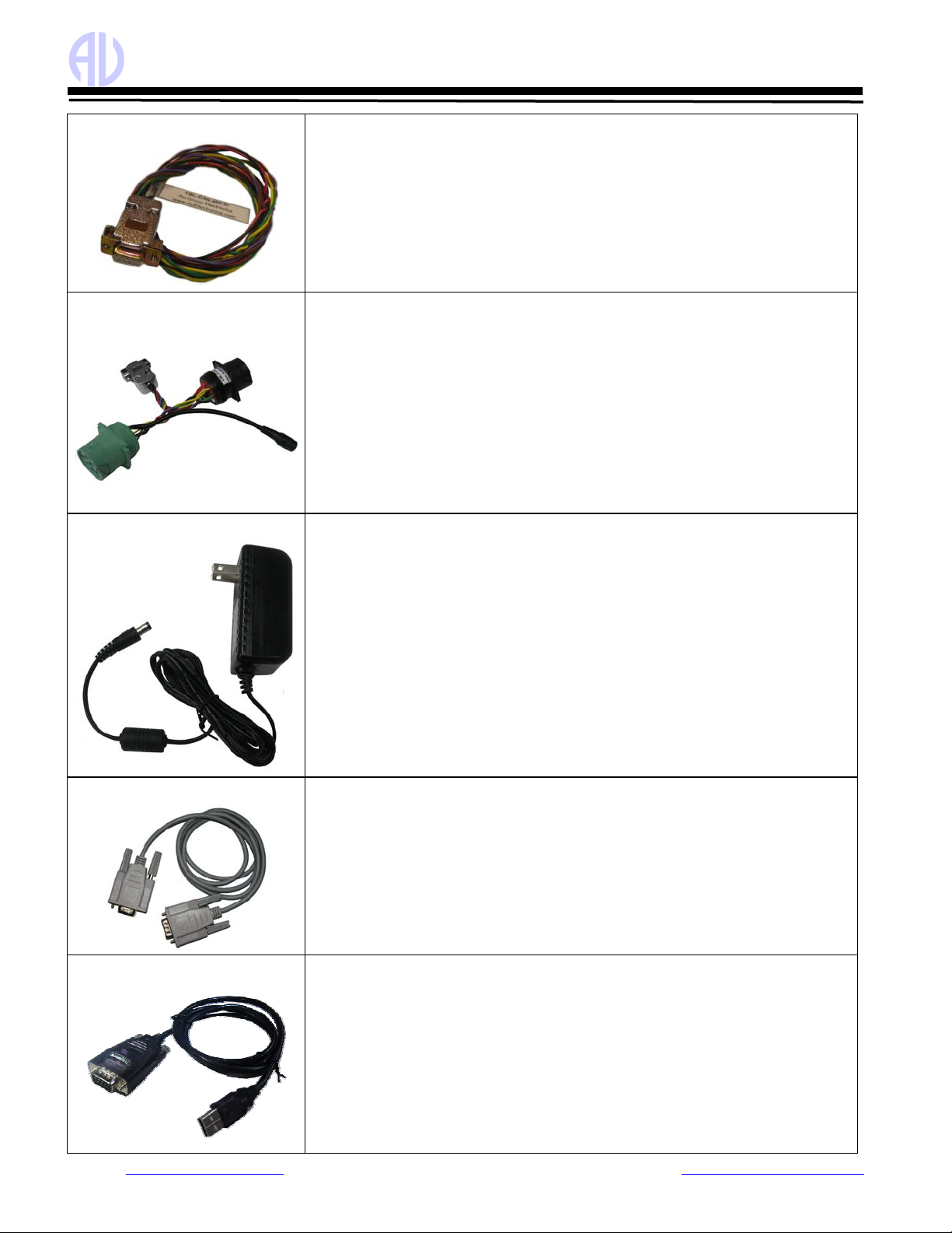
The following cables and power supply are optional components for different application, they are sold separately.
Table 1-1 Necessary accessories for Au J1939 Simulator
CBL-CAN-01
A 4-wire twisted and shield pigtail cable, it can be used to connect Au J1939
simulator on the BUS side to power supply and CAN network.
One end of the cable is a DB9 connector which mates with the DB9 male connector
at “BUS” side.
The other end of the cable consists of 4 pigtail wires which can connect power supply
and CAN network.
Red wire: Power supply, e.g. +12V DC Black wire: Ground
Yellow: CAN-H Green: CAN-L
Au Group Electronics Au SAE J1939 Simulator Gen II 1.00A User Manual Rev. G
Website: www.AuElectronics.com Support: Support@AuElectronics.com
5/36
CBL-CAN-485-01
A 6-wire color coded cable which can be used for Au J1939 devices and Au J1708
devices.
One end of the cable is DB9 female connector; it is designed to mate with Au devices
on BUS side.
The other side of the cable is a pig tail with 3 pairs of twisted color coded wires:
Red wire: Power supply, e.g. +12V DC Black wire: Ground
Yellow wire: CAN-High Green wire: CAN-Low
Violet: J1708A+ Brown: J1708B-
CBL-CAN-485-02D
CBL-CAN-485-02D is a CAN/J1939/J1708/J1587 cable equipped with a DB9 female
connector, dual SAE 9-way Receptacles (green for 500K and black for 250K CAN
baud rate) and a power Jacket
CBL-CAN-485-02D cable provides power supply, J1708/J1587 and CAN network
connection similar to what's available on trucks, RVs and School buses.
One end is a DB9 female connector, the other end are dual HD10 Serial 9-way SAE
compatible Receptacles (green for 500K CAN baud rate and black for 250K CAN
baud rate) .
It also includes a Power Supply Jacket (2.1 mm Positive center), which can supply
power to all devices connected on the cable. For SAE J1939-11, J1939-14, 250Kbps
and 500Kbps networks.
PWR-912V-CP
Wall mount AC/DC power supply can supply power to all devices connected to CBL-
J1708-02 or CBL-CAN-485-02.
Specification:
* Positive center
* Connector style: 2.1mm I.D. x 5.5mm O.D. x 12mm Female (compatible with the
power jacket of CBL-J1708-02 and CBL-CAN-485-02)
* Voltage input: 110~120V AC Input
* Voltage output: 12V DC
* Current output: 500mA Max.
* Inrush current: 40A Maximum
* Power: 6.0W
* Line Regulation: +/- 2%
* Load Regulation: +/- 5%
CBL-RS232-01
RS232 Serial Extension Cable can be used to connect computer Serial port to Au
J1939 / J1708 products (on RS232 Side).
Major Features:
* Fully shielded to prevent unwanted EMI/RFI interference
* Fully molded connectors with thumbscrews provide a quick and easy connection
every time
* Connectors: DB9 Male to DB9 Female
* All 9 connector pins are wired straight through
CBL-USB-232
The USB to Serial Converter cable can be used to connect computer USB port to Au
J1939 / J1708 products (on RS232 Side). It acts as a bridge between a USB port and a
standard Serial (RS232) port.
It is Vista, Win7, and XP compatible.
Three LED are included, Power, TX and RX. Power LED is on when USB power is
supplied. TX LED will blink when COM port is transmitting. RX LED will blink
when COM port is receiving.
It is compatible with all Au Group Electronics system products, J1939 Simulators,
J1708 Simulators, FMS Simulators, J1939 Interpreters, J1708 Interpreters, J1939
MCS, and J1939 DCS.

Au Group Electronics Au SAE J1939 Simulator Gen II 1.00A User Manual Rev. G
Website: www.AuElectronics.com Support: Support@AuElectronics.com
6/36
1.3. Major Operating Features
•Smart features: Recall last operating mode at power-on, capable of generating dynamic data, etc.
•Ease of use: No software setup experience or CAN protocol configuration skill is required. After a network is physically
connected, apply power supply, it will dynamically generate J1939 data when in dynamic mode.
•Static Mode and Dynamic Mode
oStatic mode output static J1939 signals, they can be changed manually
oDynamic mode automatically change the output value of SAE J1939 signals
oTwo modes can be switched easily (by Press and hold both Menu and Up buttons until a long beep is heard)
•PC Remote Terminal GUI (for "Plus" editions only): Display simulated J1939 signal on a computer screen
•Configurable CAN Baud Rate: Device CAN Baud Rate can be set at 250K, 500K, 62.5K, 125K, or 1M bps
•All push button control functions are available on PC Remote Terminal GUI for "Plus "editions only
•Easy in-field license upgrade feature with Au License Management Toolset.
•In-field firmware update capability
•Annual support and minor upgrade services are available
•Custom design is available upon request
1.4. Eight Editions of Au SAE J1939 Simulators
Eight editions of Au SAE J1939 simulator (Gen II) 1.00A are provided to meet various users needs (4 non-plus editions and 4
plus editions). The Plus editions have all the functions of Non-plus editions, plus a PC Remote Terminal GUI program,which
can be used to control and display detail information of simulated SAE J1939 signal on PC screen (detail information is
available at chapter 4.)
Plus Edition =Non-Plus Edition +PC Remote Terminal GUI Program
The part# for 8 editions of Au SAE J1939 simulator and necessary accessories are summarized in Table 1-2.
Table 1-2 Part# for 8 editions of Au SAE J1939 simulator Gen II 1.00A
Summary of Au SAE J1939 Simulators and Accessories Part#
Au SAE J1939 Simulator (Value Package Edition) SIMJ1939-013
Au SAE J1939 Simulator (Engine Basic Edition) SIMJ1939-001
Au SAE J1939 Simulator (Engine Premium Edition) SIMJ1939-002
Non-Plus Edition
Au SAE J1939 Simulator (Vehicle Platinum Edition) SIMJ1939-003
Au SAE J1939 Simulator (Value Package Plus Edition) SIMJ1939-014
Au SAE J1939 Simulator (Engine Basic Plus Edition) SIMJ1939-004
Au SAE J1939 Simulator (Engine Premium Plus Edition) SIMJ1939-005
Plus Edition
Au SAE J1939 Simulator (Vehicle Platinum Plus Edition) SIMJ1939-006
Service 1 year support and minor upgrades for Au SAE J1939 Simulator SVS-SIM-J1939
1.5. Basic Functions of Each Edition
Value Package editions:
•"Statically" or "dynamically" generate 6 most frequently used engine parameters
•Two push buttons (Up and Down) are used in "static mode" to adjust data outputs
•In "dynamic mode", data cycles automatically in its SAE defined range
•LEDs indicate the control step value and reflect push button operations
•Buzzer sound also reflects push button inputs, and can be enabled/disabled
Engine Basic editions:
•Includes all Value Package edition functions
•"Statically" or "dynamically" generate 23 most frequently used engine parameters
Engine Premium editions:
•Includes all Engine Basic edition functions
•Includes Premium features on SAE J1939 Transport Protocols:
oEngine DM1/DM2 warnings (support both single packet and multi-packets)

Au Group Electronics Au SAE J1939 Simulator Gen II 1.00A User Manual Rev. G
Website: www.AuElectronics.com Support: Support@AuElectronics.com
7/36
oEngine “Red Stop” and “Amber” lamp warnings
oEngine DM3
Vehicle Platinum editions:
•Includes all Engine Premium edition functions
•Includes Vehicle Network features (3 controller applications have been implemented):
oABS related signals
oTransmission related signals
oEngine Configurations
1.6. License /Firmware Upgrade and Annual Support Service
•Simulator license can be in-filed upgraded to higher editions.
Value Package editions can be upgraded to Engine Basic editions (part #: LICJ1939-004).
Engine Basic editions can be upgraded to Engine Premium editions (part #: LICJ1939-001).
Engine Premium editions can be upgraded to Vehicle Platinum editions (part #: LICJ1939-002).
Non-Plus” editions are able to be upgraded to plus editions (part #: LICJ1939-003).
"Au License Management Toolset" provides the in-filed license upgrading capability.
•Firmware can be in-field updated with Au PIC Bootloader
Firmware update code or customized codes can be re-programmed to gain new or special features.
Au J1939 Simulator 1.00A can be upgraded to Au J1939 Simulator 2.00A (part #: FIRJ1939-001)
"Au PIC Bootloader " provides the in-field firmware upgrading capability.
•Annually upgrade and support service is available at Au Group Electronics (part #: SVS-SIM-J1939).
Part numbers for license upgrading and annual service for the 8 editions of Au SAE J1939 Simulator Gen II 1.00A are
summarized in Figure 1-7.
Figure 1-7 License upgrade and annual service for SAE J1939 Simulators

Au Group Electronics Au SAE J1939 Simulator Gen II 1.00A User Manual Rev. G
Website: www.AuElectronics.com Support: Support@AuElectronics.com
8/36
Chapter 2 - Supported SAE J1939 Parameters
2.1. Value Package editions
Au SAE J1939 Simulator Gen II 1.00A Value Package editions supports 11 most frequently used engine parameters:
•Engine % Load at Current Speed (SPN 92)
•Engine Oil Pressure (PSI) (SPN 100)
•Engine Coolant Temperature (SPN 110)
•Engine Fuel Rate (SPN 183)
•Engine Speed (RPM) (SPN190)
•Engine Total Hours of Operation (Hr) (SPN 247) *
•Response for Engine Hour Request (Rx)
•Engine Address Claiming
•Engine Address CANNOT Claim
•Response for Address Claim Request (Rx)
•Address Conflict Response with Contention
* Response only with SAE J1939-21 Request PGN 59904.
2.2. Engine Basic editions
Au SAE J1939 Simulator Gen II 1.00A Engine Basic editions support all parameters listed with Value package editions, plus the
following 20 SAE J1939 engine parameters (total 31):
•Wheel Based Vehicle Speed (MPH) (SPN 84)
•Accelerator Pedal Position 1 (SPN 91)
•SAE J1939 Fuel Level 1 (SPN 96)
•Engine Turbocharger Boost Pressure (PSI) (SPN 102)
•Engine Intake Manifold 1 Temperature (F) (SPN 105)
•Battery Potential (Voltage), Switched (SPN 158)
•Engine Instant Fuel Economy (SPN 184)
•Engine Trip Distance (SPN 244)
•Total Vehicle Distance (SPN 245)
•Cruise Light (SPN 595)
•Engine Clock (HH:MM) (SPN 961, 960)
•Response for Engine Clock Request (Rx)
•Engine Clock setup (SPN 1605, 1604) (Rx)
•SAE J1939 Acknowledge protocol (ACK, NACK)
•Engine DM1 Red Stop Lamp OFF status (SPN 623)
•Engine DM1 Amber Lamp OFF status (SPN 624)
•Engine DM1 (Health-heart-beat)*
•Vehicle Identification Number (VIN) (SPN 237)
•Response for VIN global request
•Response for VIN specific request
•Water-in-Fuel Indicator (Health-heart-beat)* (SPN 97)
* Health-heart-beat: normal signal only, no warning, signal repeats in SAE defined “heart-beat” rate.
2.3. Engine Premium editions
Au SAE J1939 Simulator Engine Premium editions support all SAE J1939 parameters listed with Engine Basic editions, plus the
following 12 SAE J1939 parameters and new features (total 43):
•Engine DM1 Warning On/Off control
•Engine Red Stop Lamp On/Off
•Engine Amber Lamp On/Off
•Engine DM1 Single-Packet warning
•Engine DM1 Multi-Packet warnings
•Engine DM2 Single-Packet warning
•Engine DM2 Multi-Packet warnings
•Response for DM2 global request (Rx)
•Response for DM2 specific request (Rx)
•Engine DM3 and Engine DM2 On/Reset control (Rx)
•SAE J1939 TP.CM.BAM, TP.DT protocol
•SAE J1939 TP.CM.EndOfMsgAck, TP.CM.RTS,
TP.CM.CTS, TP.Conn.Abort, TP.DT protocol
2.4. Vehicle Platinum editions
Au SAE J1939 Simulator vehicle Platinum editions support all SAE J1939 parameters listed with Engine Premium editions, plus
18 Engine Configuration, ABS related parameters, and Transmission related parameters (total 61).
•Engine Configuration
•ABS address claim
•ABS Address CANNOT Claim
•ABS Response Request for Address Claim (Rx)
•ABS Address Conflict Response with Contention
•ABS Red Stop Lamp On/Off
•ABS Amber Lamp On/Off
•ABS DM1 (No warning or 1 warning)
•ABS Heart-beat PGN-EBC1
•Transmission address claim
•Transmission Address CANNOT Claim
•Transmission Response Request for Address Claim (Rx)
•Transmission Address Conflict Response with Contention
•Transmission Red Stop Lamp On/Off
•Transmission Amber Lamp On/Off
•Transmission DM1 (No warning or 1 warning)
•Transmission Oil Temperature
•Transmission Heart-beat PGN-ET

Au Group Electronics Au SAE J1939 Simulator Gen II 1.00A User Manual Rev. G
9
Chapter 3 - Operating Instructions
All editions of Au SAE J1939 Simulator Gen II can be operated by just controlling 3 push buttons. It generates SAE J1939
signals for product developers, testers, operators and manufacturers.
3.1. Power On
Plug in a 4-wire cable (e.g. Au Part#: CBL-CAN-01) to Au SAE J1939 Simulator Gen II BUS side DB9 male connector (pin-
out of BUS side male connector is illustrated in Figure 1 - 2). When the CBL-CAN-01 cable is used, connect the Red wire to
+12V DC power supply, Black wire to ground, White wire to CAN-H, Green wire to CAN-L. The Power LED on simulator
will light up, and simulator will resume the last saved operating mode (static mode or dynamic mode).
3.2. Operating Mode (Static/Dynamic)
After power on, Au SAE J1939 Simulator will work on either static mode or dynamic mode.
•Static mode: Au SAE J1939 Simulator Gen II generates steady SAE J1939 signals. In this mode, two push buttons
(Up and Down) can be used to change the data outputs. When no button is pushed, all data will stay at the last value.
•Dynamic mode: The value of all data will change automatically in SAE J1939 defined range
•Switch between dynamic mode and static mode: Press and hold both Menu and Up buttons until a long beep is heard
if buzzer is enabled; or both the "▼0% LED" and "▲100% LED" flip their status (from on to off or vice versa)
Au SAE J1939 Simulator Gen II equipped with 3 push buttons (Menu, Down, Up) and 9 LEDs (Figure 3-1). Each LED is
named after its function.
Figure 3-1 Position of push buttons and LEDs
3.3. Push Button Function
•Press Menu button:
oMenu button is used to control Warning LED on/off. A single press on Menu button will turn on the Warning
LED if the Warning LED was off, and vice versa.
oThe Menu button function is available only on Engine Premium editions and Vehicle Platinum editions. In
Value Package editions and Engine Basic editions, Menu button is not used. Warning LED is constant off.
oIf buzzer is enabled, a short beep will be heard upon a press on the Menu button.
In dynamic mode, the simulator automatically adjusts the control step value by itself. This will generate dynamic J1939 signals.
In static mode, all* simulated SAE J1939 signal will be controlled by the control step value, which is still able to be manually
controlled by the Up and Down buttons.
Note: * The Engine Clock is not controlled by the control step value and push buttons; it runs all by itself just like a real clock.
•Press Down button:
oDown button is used to decrease the values of all J1939 signals. A single press will decrease all data one step
from previous values until they reach the minimum values. ▼0% LED will be triggered on/off.
oIf ▼0% LED is on, press Down button one time, ▼0% LED will be off.
oIf ▼0% LED is off, press Down button one time, ▼0% LED will be on.
o80% LED blinks when control step value equals to 80%,
o60% LED blinks when control step value equals to 60%,
o40% LED blinks when control step value equals to 40%,
o20% LED blinks when control step value equals to 20%,
o▼0% LED blinks when control step equals to 0%,
oIf buzzer is enabled, a short beep will be heard upon a press on Down button.

Au Group Electronics Au SAE J1939 Simulator Gen II 1.00A User Manual Rev. G
Website: www.AuElectronics.com Support: Support@AuElectronics.com
10/36
•Press Up button:
oUp button is used to increase the values of all J1939 signal. A single press will increase all simulated data one
step to next data level until they reach the maximum values, ▲100% LED will be triggered on or off.
oIf ▲100% LED is on, press Up button one time, ▲100% LED will be off.
oIf ▲100% LED is off, press Up button one time, ▲100% LED will be on.
o20% LED blinks when control step value equals to 20%,
o40% LED blinks when control step value equals to 40%,
o60% LED blinks when control step value equals to 60%,
o80% LED blinks when control step value equals to 80%,
o▲100% LED blinks when control step value equals to the highest value, 100%.
oIf buzzer enabled, a short beep will be heard upon a press on Up button.
•Press and hold both Down + Up button for more than 1 second:
oDown + Up buttons are used to turn buzzer on/off.
oIf buzzer is on, press and hold Down + Up for more than 1 second will silent buzzer thereafter.
oIf buzzer is mute, press and hold Down + Up for more than 1 second will enable the buzzer thereafter.
oBoth ▲100% and ▼0% LED will flip their on/off status as a visual indication of this dual-button input.
oIf buzzer is enabled, a long beep will be heard to reflect the input of Down + Up button.
•Press and hold both Menu + Down button for more than 1 second:
oMenu + Down buttons are used to turn Engine DM2 warning on/Reset.
oBoth ▲100% LED and ▼0% LED will flip their status as a visual indication of this dual-button input.
oIf buzzer is enabled, a long beep will be heard to reflect the input of Menu + Down button.
oThe Engine DM2 warning messages (on premium and platinum editions) are always on after power-on. It can be
reset when an Engine DM3 PGN is received.
oFor continuous test purpose, after an Engine DM3 PGN is received, either re-power-on the simulator or press and
hold both Menu + Down button for more than 1 second will turn on the Engine DM2 warning again.
•Press and hold both Menu + Up button:
oMenu + Up buttons are used to switch between static mode and dynamic mode.
oBoth ▲100% LED and ▼0% LED will flip their status as a visual indication of this dual-button input.
oIf buzzer enabled, a long beep will be heard to reflect the input of Menu + Up button.
The push button functions are summarized in Table 3-1.
Table 3-1 Summary of Push button functions
Push Button Operation Function
Press Down button Decrease all simulated data until they reach the lowest value
Press Up button Increase all simulated data until they reach the highest value
Press Menu button DM1 Warning On/Off control (N/A for Value Package and Engine Basic editions)
Press and hold Menu button when power on Simulator will enter Bootloader mode, if no communication is detected from a PC
Bootloader program within 10 seconds, it’ll resume normal modes
Press and hold both Down + Up button Buzzer ON/OFF control
Press and hold both Menu + Up button Switch between Static/Dynamic mode
Press and hold both Menu + Down button Engine DM2 ON/Reset control (N/A for Value Package and Engine Basic editions)
3.4. LED Indicator Status
Note: Red LEDs and Green LEDs are used in this document for illustration purpose; actual product might have different LED color. Same applies to the
push buttons. Au Group Electronics reserve the right of changing the color on each LEDs and push buttons without further notification.
•When power on, both Power LED and Range LED lit, as shown in Figure 3-2.

Au Group Electronics Au SAE J1939 Simulator Gen II 1.00A User Manual Rev. G
Website: www.AuElectronics.com Support: Support@AuElectronics.com
11/36
Figure 3-2 Power on, both Power and Range LED lit
All SAE J1939 data can be changed within the SAE defined range from 0 to 100 control steps (named 0% to 100%
control step value from now on), 6 LEDs are used to identify the control step value in the range of 0%, 20%, 40%,
60%, 80%, and 100%.
•▲100% LED will be on or off with a press on the Up button, accompany with the increasing brightness of Range
LED. A press on the Up button will also increase the control step value and all simulated data.
oWhen control step value equals to 0%, the ▼0% LED blinks.
oWhen control step value equals to 20%, 20% LED blinks.
oIf keep pressing Up button, the control step value will keep increasing. The 20% LED will then be always on,
as shown in Figure 3-3. This indicates a data range from 21- 39%.
Figure 3-3 Power, Range, 20% LED on, indicates data ranges from 21% to 39%
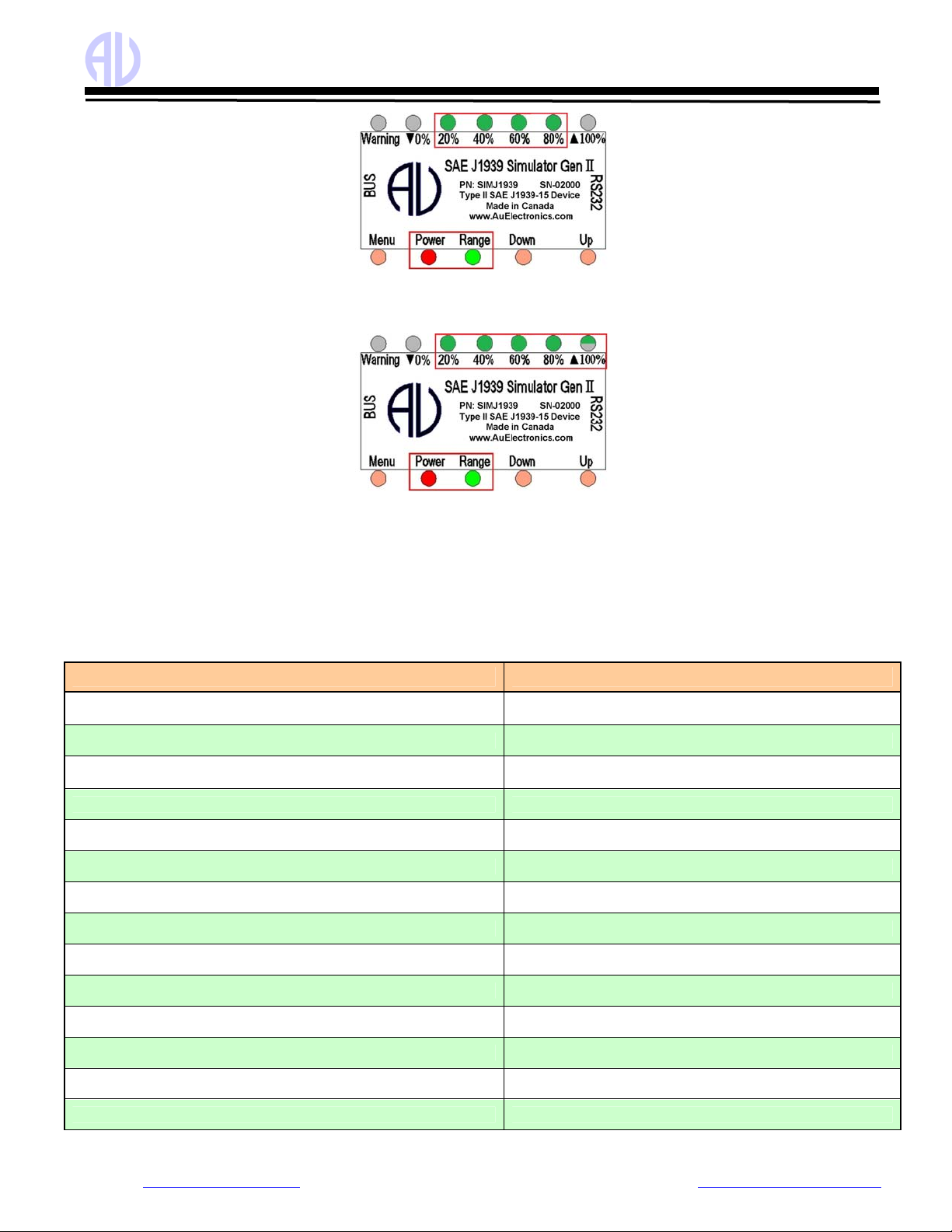
oWhen control step value equals to 40%, 40% LED blinks.
oIf keep pressing Up button, the control step value will keep rising, 20% and 40% LED will be always on, as
shown in Figure 3-4. It indicates the data range from 41% to 59%.
Figure 3-4 Power, Range, 20%, 40% LED on, indicates data ranges from 41% to 59%
oWhen control step value equals to 60%, 60% LED blinks
oIf keep pressing Up button, the control step value will keep rising, the 20%, 40%, and 60% LED will be on, as
shown in Figure 3-5, it indicates the data range from 61% to 79%.
Figure 3-5 Power, Range, 20%, 40%, 60% LED on, indicates data ranges from 61% to 79%
oWhen control step value equals to 80%, 80% LED blinks.
oIf keep pressing Up button, the control step value will keep rising, 20%, 40%, 60%, and 80% LED will be on,
as shown in Figure 3-6, it indicates the data range from 81% to 99%.
Au Group Electronics Au SAE J1939 Simulator Gen II 1.00A User Manual Rev. G
Website: www.AuElectronics.com Support: Support@AuElectronics.com
12/36
Figure 3-6 Power, Range, 20%, 40%, 60%, 80% LED on, indicates data ranges from 81% to 99%
oWhen control step value equals to 100%, 20%, 40%, 60%, and 80% LED will be constant on. ▲100% LED
blinks, as shown in Figure 3-7.
Figure 3-7 Power, Range, 20%, 40%, 60%, 80% are constant on, “▲100%” LED blinks, indicating data reaches 100%
•▼0% LED will be on or off when pressing Down button, accompany with the decreasing brightness of Range LED. A
press on the Down button will also decrease the control step value and all simulated data. When the control step value
equals to 0%, ▼0% LED blinks.
The control step value LED indicator status is summarized in Table 3-2.
Table 3-2 Control step value vs. LED indicator status (in Static Mode)
Operation LED Status
Step 1. Connect +12 V DC power supply Power, Range LED on, the rest LED will recall the last saved
status in Static mode
Step 2. Press Down button ▼0% LED on/off
Step 3. Continue press Down button until the control step value equals to
0% ▼0% LED blink
Step 4. Press Up button ▲100% LED on/off
Step 5. Continue press Up button for control step value 1 to 19% Power, Range LED constant on
Step 6. Continue press Up button for control step value 20% Power, Range LED on, 20% LED Blink
Step 7. Continue press Up button for control step value 21 to 39% Power, Range LED on, 20% LED on
Step 8. Continue press Up button for control step value 40% Power, Range, 20% LED ON, 40% LED Blink
Step 9. Continue press Up button for control step value 41 to 59% Power, Range, 20%, 40% LED on
Step 10. Continue press Up button for control step value 60% Power, Range, 20%, 40% LED on, 60% LED blink
Step 11. Continue press Up button for control step value 61 to 79% Power, Range, 20%, 40%, 60% LED on
Step 12. Continue press Up button for control step value 80% Power, Range, 20%,40%, 60% LED on, 80% LED blink
Step 13. Continue press Up button for control step value 81 to 99% Power, Range, 20%, 40%, 60%, 80% LED on
Step 14. Continue press Up button for control step value 100% Power, Range, 20%, 40%, 60%, 80% LED on, ▲100% blink
Au Group Electronics Au SAE J1939 Simulator Gen II 1.00A User Manual Rev. G
Website: www.AuElectronics.com Support: Support@AuElectronics.com
13/36
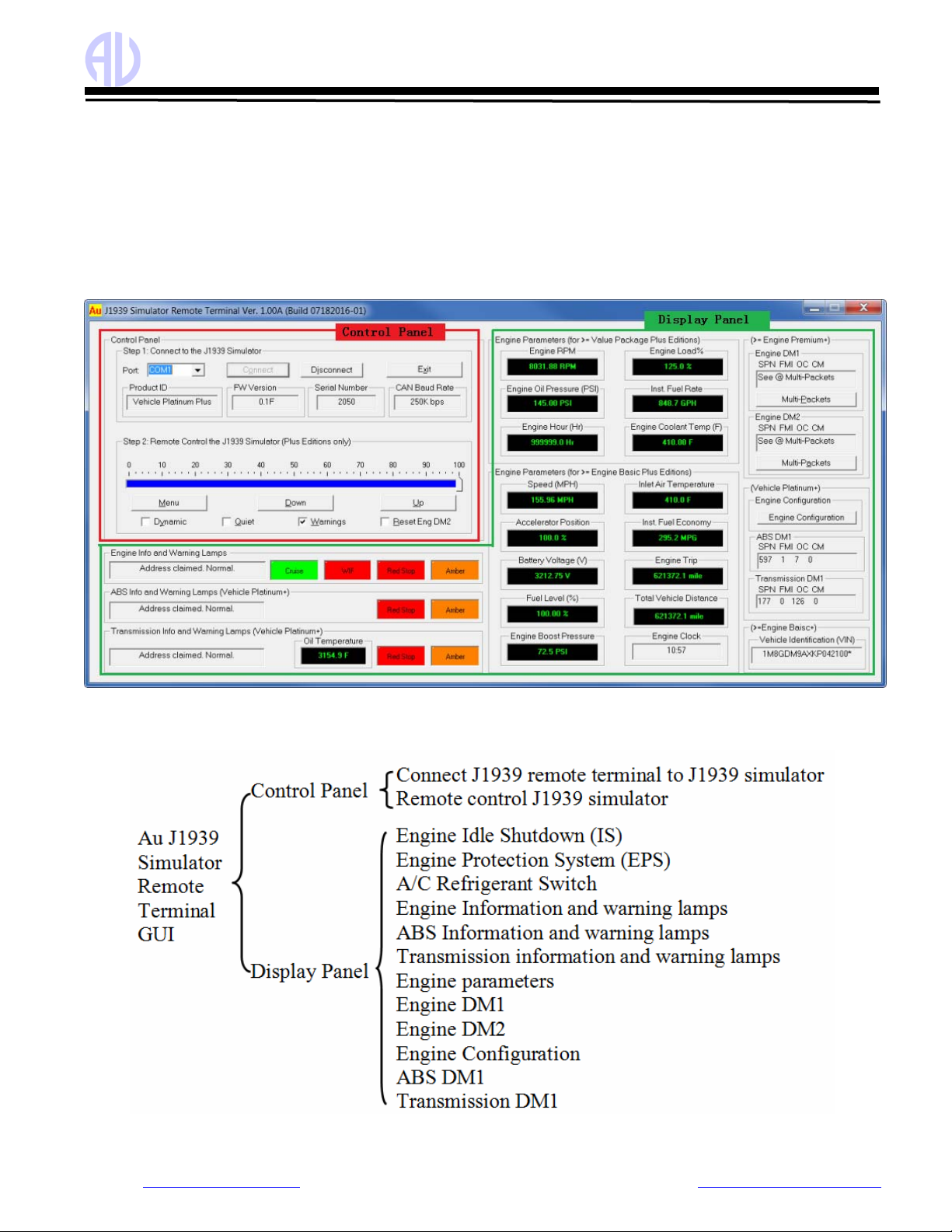
Chapter 4 - Au J1939 Simulator Remote Terminal GUI
For all Au SAE J1939 Simulator Gen II 1.00A “Plus” editions, the “Au J1939 Simulator Remote Terminal Ver. 1.00A” GUI can
be used to control and display simulated SAE J1939 signals on PC screen.
The Remote Terminal GUI (Graphic User Interface) includes a control panel and a display panel. Control panel is located in the
up-left corner. All the other area is used for displaying information like engine/ABS/Transmission info, warning lamp, etc. as
shown in Figure 4-1, 4-3, 4-4.
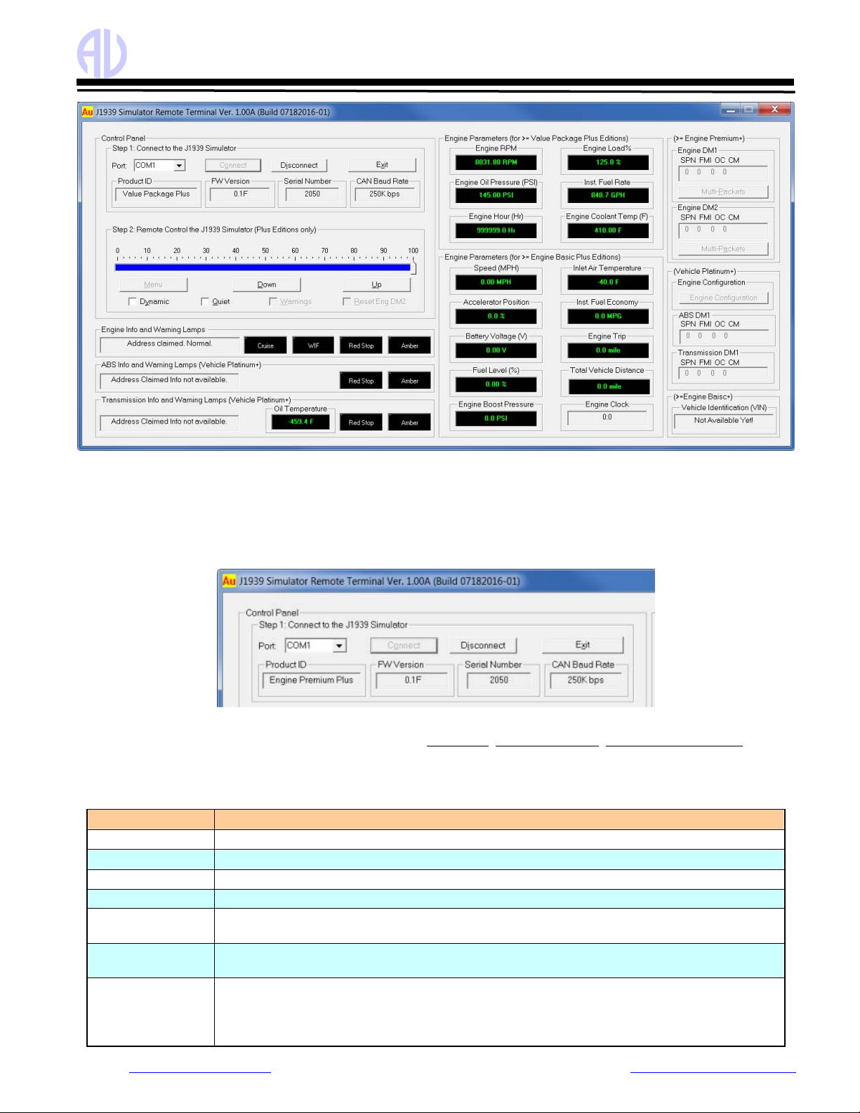
Figure 4 -1 shows Remote Terminal GUI for Au SAE J1939 Simulator Gen II 1.00A vehicle platinum plus edition. All
features are active.
Figure 4-1 Au J1939 Simulator Remote Terminal GUI – Gen II 1.00A Vehicle Platinum Plus Edition
Au J1939 Simulator Remote Terminal Structure is summarized in Figure 4-2.
Figure 4-2 Au J1939 Simulator Remote Terminal Structure

Au Group Electronics Au SAE J1939 Simulator Gen II 1.00A User Manual Rev. G
Website: www.AuElectronics.com Support: Support@AuElectronics.com
14/36
Figure 4 -3 shows the Remote Terminal GUI for Au SAE J1939 Simulator Gen II 1.00A Engine Premium Plus edition. Engine
info and warning lamps, engine basic parameters, Engine DM1, and Engine DM2 are included.
ABS info, Transmission info and engine configuration are NOT available.
Figure 4-3 SIMJ1939 1.00A GUI –Engine Premium Plus Edition
Figure 4 -4 shows the Remote Terminal GUI for Gen II 1.00A Engine Basic Plus edition.
Engine information, cruise lamps, and engine basic parameters are active.
ABS info, Transmission info, engine DM1, engine DM2, and engine configuration are NOT available.
Figure 4-4 SIMJ1939 GUI - Engine Basic Plus Edition
Figure 4 - 5 shows the Remote Terminal GUI for Au SAE J1939 Simulator Gen II 1.00A Value Package Plus edition, 6 most
frequently used Engine Parameters are available:
Au Group Electronics Au SAE J1939 Simulator Gen II 1.00A User Manual Rev. G
Website: www.AuElectronics.com Support: Support@AuElectronics.com
15/36
Figure 4-5 SIMJ1939 GUI - Value Package Plus Edition
Following paragraphs will explain how to use the GUI to remote control Au SAE J1939 Simulator Gen II 1.00A Plus editions.
4.1. Control Panel – Step 1: Connect to J1939 Simulator
Connect the simulator to power supply and a CAN network, and then connect it to PC serial port.
Select serial port from the “Port” drop down list Æclick “Connect” button Æmessages about the connected J1939 simulator
edition (Product ID, FW version, Serial Number, CAN Baud Rate) will display, as shown in Figure 4-6.
Figure 4-6 SIMJ1939 GUI control panel step 1 - Connect to J1939 Simulator
Note: The control panel step 1 can always be used to display Product ID, Simulator Version, Product Serial Number, and CAN
Baud Rate for all Au J1939 simulator editions (both plus edition and non-plus edition).
The function of step 1 control items is summarized in Table 4-1
Table 4-1 Function summary of step 1 control items
Items Function
Port Serial port can be selected from drop down list (COM1 to COM30)
Connect Click “Connect” button to connect J1939 simulator with selected PC serial port.
Disconnect Click “Disconnect” button to release the selected PC serial port.
Exit Click “Exit” button to close the J1939 remote terminal program
Product ID Display the current edition of J1939 simulator that’s hooked up with the serial port. (The
demonstration in Figure 4-6 is a Vehicle Platinum Plus Edition)
Simulator Version Display the current version of J1939 simulator that’s hooked up with the serial port. (The
demonstrated version of the connected simulator in Figure 4-6 is 0.1B)
Product Serial
Number
Display the serial number of J1939 simulator that’s connected to the serial port. (The
demonstrated serial number for the connected simulator in Figure 4-6 is 2000)
CAN Baud Rate CAN Baud Rate of J1939 simulator, can be configured to : 62.5K, 125K, 250K, 500K, 1M bps
Please refer to the appendix B for detail information on how to configure CAN Baud Rate.

Au Group Electronics Au SAE J1939 Simulator Gen II 1.00A User Manual Rev. G
Website: www.AuElectronics.com Support: Support@AuElectronics.com
16/36
4.2. Control Panel – Step 2: Remote control the J1939 Simulator
Remote control includes 1 scale bar, 3 push buttons (Menu, Down, Up), and 4 check boxes (Dynamic, Quite, Warnings,
Reset Eng DM2), as shown in Figure 4-7. These tools are able to remote control the output/simulated signal of the Au J1939
Simulator PLUS editions.
Figure 4 - 7 SIMJ1939 GUI control panel step 2 – Remote control the J1939 Simulator
The scale bar represents the control step values from 0% to 100%. The sliding action can be made by 3 methods: keyboard,
mouse or Down/Up buttons from remote terminal. They are summarized in Table 4-2
Table 4-2 Control Methods for Scale Bar
Action Function
Left Click Left click bring the slide to the desire location
Mouse Drag Click and hold left button drag the slide to desire location
▲or ►Increase the scale range in 1 interval
▼or ◄Decrease the scale range in 1 interval
Pg Up Increase the scale range in 10 interval
Keyboard
Pg Dn Decrease the scale range in 10 interval
Down button Decrease the scale range in 1 interval
Remote
terminal Up button Increase the scale range in 1 interval
The function for the 3 push buttons and 4 check boxes is listed in Table 4-3.
Table 4-3 Functions for push button and check boxes in step 2
Tool Function
Menu Turn on/off warning (see note below)
Down Decrease the control step value in 1
Button
Up Increase the control step value in 1
Dynamic Switch between dynamic mode / static mode
Quite Turn on/off buzzer
Warning Turn on/off Eng/ABS/Trans DM1 warnings
Check box
Reset Eng DM2 Turn on/reset all Engine DM2 code
Note: Menu button is active only in the Engine Premium Plus edition and Vehicle Platinum Plus edition.
4.3. Display Panel – Engine info and Warning Lamps
It displays the engine address claiming information, 1 information lamp (Cruise lamp), and 3 warning lamps for engine (WIF -
water in fuel, Red Stop, Amber), as shown in Figure 4-8. The warning lamps will turn on/off based on the scale range, see
Table 4-4 to Table 4-7 for more information.
Figure 4-8 Display Engine info and warning lamps
4.4. Display Panel – ABS info and Warning Lamps
It displays the ABS address claiming information and 2 warning lamps for ABS (Red Stop, Amber) (Figure 4-9).
Figure 4-9 Display ABS info and warning lamps

Au Group Electronics Au SAE J1939 Simulator Gen II 1.00A User Manual Rev. G
Website: www.AuElectronics.com Support: Support@AuElectronics.com
17/36
4.5. Display Panel – Transmission info and Warning Lamps
It displays the transmission address claiming information, transmission oil temperature, and 2 warning lamps for transmission
(Red Stop, Amber), as shown in Figure 4-10.
Figure 4-10 Display transmission info and warning lamps
4.6. Display Panel – Value Package Parameters
SIMJ1939 1.00A Value Package plus edition
display the following 6 most frequently used engine
parameters, as shown in figure 4-11.
•Engine Speed(RPM)
•Engine oil pressure (PSI)
•Engine hour (Hr)
•Engine load percentage (%)
•instant fuel economy (MPG)
•Engine coolant temperature
Figure 4-11 SIMJ1939 1.00A Engine basic parameters
4.7. Display Panel – Engine Basic Parameters
SIMJ1939 1.00A Engine Basic plus edition display
the following 17 engine parameters, as shown in
figure 4-12:
•Engine Speed(RPM)
•Engine oil pressure (PSI)
•Engine hour (Hr)
•Engine load percentage (%)
•Instant fuel rate (GPH)
•Engine coolant temperature (F)
•Vehicle speed (MPH)
•Accelerator position (%)
•Battery voltage (V)
•Fuel level (%)
•Engine boost pressure (PSI)
•Inlet air temperature (F)
•Instant fuel economy (MPG)
•Engine trip (mile)
•Total vehicle distance (mile)
•Engine clock (HH:MM)
•Vehicle Identification Number (VIN)
Note: Engine Clock is not controlled by the control step
value, it runs by itself like a real clock, and can be setup by
PGN 54528.
Figure 4-12 SIMJ1939 1.00A Engine basic parameters
4.8. Display Panel – Engine DM1
Engine DM1 message could be single packet (without warning or with 1 warning) or multi-packet.
When engine DM1 is a single packet message, SPN, FMI, OC, CM will display (Figure 4-13).
when engine DM1 is a multi-packet message, “see @ Multi-Packets” will display, “Multi-packets” button will be active (Figure
4-14), click on it, the whole list of engine DM1 will display (Figure 4-15).
If Engine DM1 or DM2 warning is off, a SAE defined non-warning message will be shown as (0,0,0,0).

Au Group Electronics Au SAE J1939 Simulator Gen II 1.00A User Manual Rev. G
Website: www.AuElectronics.com Support: Support@AuElectronics.com
18/36
Detail data information of engine DM1 multi-packet is showing in Table 4 – 4 to 4 – 7.
Table 4 – 4 Engine DM1 Multi-Packets (1 – 16)
1 2 3 4 5 678910 11 12 13 14 15 16
SPN 110 100 97 94 168 157 174 175 111 558 626 1081 190 91 190 626
FMI 0 1 15 2 1 4 3 2 1 2 11 11 2 4 0 2
OC 1 5 9 13 17 21 25 29 33 37 41 45 49 53 57 61
CM 0 0 0 0 0 0 0 0 0 0 0 0 0 0 0 0
Table 4 – 5 Engine DM1 Multi-packets (17 – 32)
17 18 19 20 21 22 23 24 25 26 27 28 29 30 31 32
SPN 190 558 16 626 51 52 72 94 108 102 111 174 1209 2791 176 175
FMI 10 3 4 8 3 33 4 4 4 3 2 4 3 2 3
OC 65 69 73 77 81 85 89 93 97 101 105 109 113 117 121 125
CM 0 0 0 0 0 00 0 0 0 0 0 0 0 0 0
Table 4 – 6 Engine DM1 Multi-Packets (33 – 48)
33 34 35 36 37 38 39 40 41 42 43 44 45 46 47 48
SPN 102 102 102 102 102 102 102 102 102 102 102 102 102 102 102 102
FMI 0 1 2 3 4 5 6 7 8 9 10 11 12 13 14 15
OC 1 1 1 1 1 1 1 1 1 1 1 1 1 1 1 1
CM 0 0 0 0 0 0 0 0 0 0 0 0 0 0 0 0
Table 4 – 7 Engine DM1 Multi-Packets (49 – 64)
49 50 51 52 53 54 55 56 57 58 59 60 61 62 63 64
SPN 102 102 102 102 102 102 102 102 102 102 102 102 102 102 102 102
FMI 16 17 18 19 20 21 22 23 24 25 26 27 28 29 30 31
OC 1 1 1 1 1 1 1 1 1 1 1 1 1 1 1 1
CM 0 0 0 0 0 0 0 0 0 0 0 0 0 0 0 0

Au Group Electronics Au SAE J1939 Simulator Gen II 1.00A User Manual Rev. G
Website: www.AuElectronics.com Support: Support@AuElectronics.com
19/36
4.9. Display Panel – Engine DM2
Engine DM2 message could be a single packet or multi-packet.
If engine DM2 is a single packet, SPN, FMI, OC, CM will display (Figure 4-16).
If engine DM2 is a multi-packet, “see @ Multi-Packets” will display, “Multi-packets” button will be active (Figure 4-17),
Click on it, the whole list of engine DM2 will display (Figure 4-18).
*Note: The "Multi-Packets" buttons are used as a trigger for a pop-up sub-window which will display all DM1/DM2 code. It is
not used to turn on/off Multi-Packets DM1/DM2.
Engine DM1 Multi-Packets will
be available when both of the
following two conditions are met
• Warning is on
• Control step value is 100
Engine DM2 Multi-Packets will be
available when:
Control step = 100.
When "Reset Eng DM2" is checked,
Engine DM2 will be reset to 0.

Au Group Electronics Au SAE J1939 Simulator Gen II 1.00A User Manual Rev. G
Website: www.AuElectronics.com Support: Support@AuElectronics.com
20/36
4.10. Display Panel – Engine Configuration
Engine Configuration PGN includes 39 bytes of messages, which require
transport protocol for multi-packet communication.
“Engine Configuration” button will be active on the remote terminal GUI for
Vehicle Platinum editions, as shown in Figure 4 - 19.
Figure 4-19 Engine Configuration
Click on "Engine Configuration" button, detail information will show up, as shown in Figure 4-20.
Figure 4-20 Display panel – Engine Configuration
4.11. Display Panel – ABS DM1
ABS warning is OFF ABS warning is ON
ABS DM1 is a single-packet PGN.
SAE defined non-warning message will
show as (0,0,0,0)
a Brake Switch signal low warning will show
as (597,1,7,0)
4.12. Display Panel – Transmission DM1
Transmission warning is OFF Transmission warning is ON,Transmission DM1 is a single-
packet PGN. SAE defined non-warning message will
show as (0, 0, 0, 0)
a transmission warning will show as
(177, 0, 126, 0)
Other manuals for SAE J1939
2
This manual suits for next models
8
Table of contents
Other AU Switch manuals


