Hored PS3016S User manual

User Manual
PS3016S
16 Port Layer2 Managed PoE Switch

Installation manual introduction
The Product installation manual mainly describes PS1016S PoE switch hardware features,
installation methods, and precautions during the installation
This manual includes the following chapters:
Chapter 1: Product Introduction. Briefly describes the basic features of the switch and the
appearance details.
Chapter 2: Product Installation. Guide the switch hardware installation methods and
precautions.
Chapter 3: Hardware Connections. Guide the connection between switches and other
devices and precautions.
Chapter 4: Technical Specifications.
NOTE:To avoid potential device damage and personal injury, read the
related information in this manual before installing the device.
Agreement The term "switch" mentioned in this manual, unless otherwise specified, refers to
16-port 10/100Mbps managed PoE switch, hereinafter referred to as PS1016S
Some pictures for the schematic, the product itself and pictures may be different
Due to product version upgrades or other reasons, the contents of this
document may be updated from time to time. Unless otherwise agreed, this
document is for guidance only. All statements, information and suggestions in this
document do not constitute any form of guarantee.
This icon indicates the items to be cautioned in the operation. If the operation is
wrong, the equipment may be damaged and other adverse consequences.

Chapter 1 Product Introduction
1.1Product introduction
PS3016S is managed PoE switch for security transmission and WIFI coverage, meet
the WIFI AP, IP-camera, WIFI bridge, IP phones and other types of equipment PoE
power supply needs. Products using a new generation of high-performance
hardware and software platforms, providing flexible, cost-effective 10/100Mbps
access and gigabit uplink ports, support Layer 2 management, complete security
mechanisms, improved ACL / QoS strategy and rich VLAN capabilities, it is easy to
manage and maintain, meet the users' requirements for network equipment easy to
manage, high security and low cost. It is suitable for network access, aggregation
and core applications in campus, hotel and enterprise campus.
PoE (Power over Ethernet) refers to the power over Ethernet technology. It refers to
the transmission of data signals to some IP-based terminals (such as IP phones,
wireless access point APs, network cameras, etc.) and also provide DC power supply
technology. These devices that accept DC power supply are called powered devices
(PDs)
1.2Packing list
Open the package carefully check the following list
Commodity
Quantity
Description
PoE switch
1pcs
No
Power cord
1pcs
Optional
Bracket
2pcs
Fixed on rack mount
User
manual
1pcs
Guide users to install switch

1.3Appearance
◼Front Panel
Including indicators, RJ45 port, shortcut buttons, RST button, SFP port, CONSOLE port, as
shown in below
◼Indicators
PS3016S The indicator working status is shown as the following table
Indicator
s
Title
Color
Work
status
Description
PWR
Power
indicator
Red
Solid
Power is normal
Off
No power, the power switch is
not turned on, power supply is
abnormal
POE
POE
power
indicator
Yellow
Solid
The corresponding RJ45 port is
connected to the powered
device and the power supply is
normal
Off
The corresponding RJ45 port is
not connected to the powered
device or the power supply is
abnormal
LINK/AC
T
Connectio
n indicator
Green
Blinking
A valid link is established
Off
A link is not established
SYS
System
indicator
Green
Blinking
System work well
Off
System error, software is
damaged

Shortcut button
◆AI QOS: Improve video data processing capabilities and improve the monitoring of
Caton and Mosaic phenomena in the network
◆AI Extend:1-8 port rate down to 10Mbps, but the transmission distance up to 250
meters
◆Ai VLAN: Isolating ports 1-6 from each other, suppress network storms effectively
and improve network performance
◆AI PoE: Detect PD, power failure and restart dead equipment
RJ45 Port
PS3016S support 16x 10/100Mbps PoE port, all ports support IEEE802.3af and IEEE802.3at
standard .In addition PS3016S also provides two 10/100/1000Mbps adaptive RJ45 port as the
uplink port, with SFP1, SFP2 form a Combo port. At the same time Combo port two ports can
only use one. Two Combo port shared 17, 18 Indicator light
SFP Port
PS3016S provide 2 Combo Gigabit SFP optical ports (SFP1, SFP2), can be inserted into the
Gigabit SFP module
RST Button
When the switch is powered on, press the button with the needle to release the device and enter
the restarting state. When the SYS lamp restarts, the device restarts. When the switch is
powered on, press and hold the button for more than 5s to release the button and enter the reset
state. When SYS is re-lit, the device is reset successfully
Console port
Console port used to connect to computer or other terminal to manage or configure the switch.
◼Back Panel
Including: power socket, ground terminal

Power socket
Connect the power cable to the switch PS3016S with an AC power supply of 100-240V to
50/60Hz
Ground terminal
Use a wire ground to prevent lightning strikes. To avoid lightning strikes on the product and
extend the life of the product
Chapter 2 Installation
2.1 Installation Precautions
Note:To avoid improper use of equipment damage and personal injury, please
observe the following precautions
◼Installation safety precautions
⚫The power should be kept off during the installation, while wearing anti-static wrist,
and to ensure well touch between anti-static wrist and skin to avoid potential safety
hazard;
⚫The switch just work normally when it is powered by the correct power supply. Make
sure that the power supply voltage matches the voltage indicated by the switch
⚫Before powering on the switch, make sure that the power circuit is not overloaded,
which may affect the normal operation of the switch and even cause unnecessary
damage
⚫To avoid the risk of electric shock, do not open the case while the switch is working.
Do not open the case even when it is not powered
⚫Before cleaning the switch, unplug the switch from the power cord and do not wipe it
with wet cloth. Do not wash it with liquid
Temperature and humidity
To ensure the long-term stability working of the switch , please maintain a certain
temperature and humidity environment. High or low humidity easily lead to leakage of
insulation materials, deformation and even the corrosion of metal parts, the
temperature is too high will accelerate the aging process of insulating materials,

seriously affecting the service life of equipment. The normal operation of this series of
switches and storage temperature / humidity are as follows
Environmental
description
temperature
Relative humidity
Working
environment
0℃~40℃
10%~90% RH no
condensation
Storage
environment
-40℃~70℃
5%~90% RH no
condensation
Altitude
Products with this logo are only for safe use in areas below 2000m altitude
Dust-proof
Dust on the switch surface will cause electrostatic adsorption, poor contact of the metal
contacts. Although the device itself has done some measures in anti-static, but when the
static electricity exceeds a certain intensity, it will still cause fatal damage to the electronic
components on the internal circuit board. In order to prevent static electricity from affecting
the normal operation of the equipment, please note the following:
Regular dust, keep the indoor air clean;
Make sure the equipment is well grounded to ensure smooth transfer of static electricity
Electromagnetic interference
Electromagnetic interference have an impact on the device capacitance, inductance and
other electronic components by capacitive, inductive coupling, impedance coupling and
other conductive, in order to reduce the adverse effects caused by electromagnetic
interference, please note the following:
Power supply system to take the necessary anti-grid interference measures;
Switches should be far away from high-frequency high-power, high-current devices, such
as wireless transmitters;
If necessary, take electromagnetic shielding measures
Lightning protection
When a lightning strike occurs, a strong current will be generated in an instant cause fatal
damage to electronic equipment. To achieve better lightning protection, please note the
following:
Make sure the rack and the ground to maintain good contact;
Make sure the power outlet is in good contact with the earth;
Reasonable wiring, to avoid the internal sense ray;
Outdoor wiring, it is recommended to use the signal lightning protection device
Installation desk requirement
Regardless of whether the switch is installed in a rack or on another horizontal workbench,
be aware of the following:
Make sure the rack or workbench is stable, strong, and can withstand at least 5.5Kg
weight;

Make sure the rack has a good cooling system, or maintain good indoor ventilation;
Make sure the rack is well grounded, the power outlet and switch are within 1.5 meters
Prepare tools for installation
You may need to use a screwdriver during installation, electrostatic wrist strap, fiber optic
cable and other tools to prepare your own
2.2 Product installation
19-inch standard rack installation
PS3016S is designed according to the standard 19-inch rack size, you can easily install to the
rack, the specific installation steps are as follows:
1) Check rack grounding and stability;
2) Install the two L-brackets in the accessory on each side of the switch panel and secure
with the screws provided in the accessory
3) place the switch in an appropriate place in the rack and be supported by the bracket.
Screw the L-shaped bracket to the guide groove fixed on both ends of the rack to ensure
that the switch is stable and horizontally installed on the rack
Note:
Good grounding rack is anti-static equipment, anti-leakage, lightning protection, anti-
jamming important guarantee, so to ensure that the rack ground wire properly installed;
Installation equipment within the rack from the bottom up, to avoid overload
installation;
Avoid placing other heavy objects on switch to avoid accidents;
Ensure heat dissipation and air circulation.
Chapter3 Hardware connection
3.1RJ45 port connection
Connect the RJ45 port of the switch and the corresponding network device via cables, the
POE power supply function of the switch is default enabled on the downlink port of the
switch, which can be used for IEEE802.3af or IEEE802.3at standards powered devices such
as APs, bridges, and network cameras

Note:
When the switch connected workstations, servers, routers or other ethernet devices the
cable length should be within 100 meters;
The Auto-MDI / MDIX ethernet interface is enabled by default. Category 5,the standard
network cable or crossover cable can be used for Ethernet connection.
Do not connect the RJ45 port to the phone line
3.2 SFP Port connection
PS3016S SFP port only support Gigabit fiber module. Recommended use of standard SFP
module products
The process of installing a fiber module on a switch is as follows:
First, grasp the optic fiber module from the side, insert it smoothly along the SFP port slot
until the optic fiber module and switch are in close contact;
Second, confirm the Rx and Tx ports of the fiber module when connecting, insert one end of
the fiber into the Rx and Tx ports correspondingly, ensure that the Tx and Rx ends of the
interface are connected correctly and the other end of the fiber is connected to another
device;
Third, please check the corresponding indicator light status after power on. If the light
blinking that the link is properly connected, if the light is off , the link is failure, please check
the line to confirm that the corresponding equipment is enabled.

Note:
Does not allow excessive bending fiber, the radius of curvature should not be less
than 10cm;
Ensure the cleanliness of the fiber surface;
Please do not look directly into the optical fiber connector with your eyes as this may cause
eye injury
3.3 Check before power on
Check whether the outlet power supply meets the switch specifications;
Check the power, switches, racks and other equipment have been properly grounded;
Check whether the switch and other network devices are connected properly
3.4 Device initialization
The switch automatically initializes when the power switch is turned on.
Indicator will appear the following situation:
After the power is turned on, the power indicator remains on, the other indicator is off at
this time;
After about 1 second, all lights except for the power light turn on for about 35 seconds and
then turn off; when the SYS light goes flashing, the system runs normally
Port LEDs indicates the connection status of each port, indicating that the switch has
started to work normally
3.5 Web Login
Step1、In the normal operation of the device, connect the computer to the switch's RJ45 port by
network cables

Step 2、Manually changed the computer IP address to 192.168.254.X (X 为2~254),subnet mask
is255.255.255.0
Step3、Open computer's browser, type 192.168.254.1 in the address box, hit the Enter key
Step4、Enter the default username and password “admin” and then click Login

Step5、Entered the switch web management interface successfully when you see picture as
below, you can begin to configure the switch

Chapter 4 Hardware Specifications
4.1Hardware Specifications
Standard
IEEE 802.3i IEEE 802.3u IEEE 802.3x
IEEE 802.3ab IEEE 802.3af IEEE 802.3at
Port
16 10/100Mbps RJ45 port
2 10/100/1000Mbps RJ45 port
2 Gigabit SFP port
1 Console port
PoE
16 10/100 Mbps RJ45 port support PoE+ power
Total max power 150W
Single max power 30W
indicators
18 Link/Act indicator
16 POE indicator
1 SYS indicator
1 Power indicator
Performance
Forwarding mode: store and forward
Backplane bandwidth:7.2Gbps
Packet forwarding rate:5.36Mpps
Support 8K MAC address table depth
Lightning
protection
6KV
Input Power
100-160V/50-60Hz
Size(L×W×H)
440mm×178mm×44mm

4.2Software Specifications
Protocol
standard
IEEE 802.3:Ethernet Media Access Control (MAC) Protocol
IEEE 802.3i:10BASE-T Ethernet
IEEE 802.3u:100BASE-TX Fast Ethernet
IEEE 802.3ab:1000BASE-T Gigabit Ethernet
IEEE 802.3z:1000BASE-X Gigabit Ethernet (fiber)
IEEE 802.3ad:Standard method for performing link
aggregation
IEEE 802.3x:flow control
IEEE 802.1p:LAN Layer 2 Qos/Cos protocol for traffic priority
(multicast filtering)
IEEE 802.1q:VLAN
IEEE 802.1d:STP Spanning tree
IEEE 802.1s:MSTP Spanning tree
IEEE 802.1w:RSTP Spanning tree
IEEE 802.3af
IEEE 802.3at
Shortcut
function
One key AI VLAN
One key AI Extend(1-8 port 250meters PoE distance)
One key AI PoE
One key Q0S (Video priority)
DHCP
Support DHCP Snooping
VLAN
Support 4K VLAN
Support 802.1Q VLAN、MAC VLAN ,IP VLAN
Voice VLAN
MAC address
table
Comply the IEEE 802.1d standard
Support MAC address learning and aging automatically
Support static, dynamic, filter address table
Safety
Password protection
Support based on the port number, IP address, MAC address
restrictions on user access
Support HTTPS、SSL V3、TLS V1、SSH V1/V2

Support IP-MAC-PORT ternary binding
Support ARP protection, IP source protection, DoS protection
Support DHCP Snooping、DHCP attack protection
Support 802.1X certificated、AAA
Support port security, port isolation
Support CPU protection
POE
management
Support POE power limit
Support POE chip status view
Support setting PoE port priority
Support setting PoE power supply time period
Access control
(ACL)
Support L2 (Layer 2) ~ L4 (Layer 4) packet filtering
Support port mirroring, port redirection, flow rate limiting, QoS
re-marking
Quality of
Service (QoS)
Support 8 port queue
Support port priority, 802.1p priority, DSCP priority
Support SP、RR、WFQ Priority scheduling algorithm
Spanning Tree
Support STP(IEEE 802.1d),RSTP(IEEE 802.1w) and
MSTP(IEEE 802.1s) protocol
Support loop protection, root bridge protection, TC protection,
BPDU protection, BPDU filtering
Multicast
Support IGMP v1/v2 Snooping
Support fast leave mechanism
Support multicast VLAN
Supports multicast filtering, packet statistics, and unknown
multicast discards.
Storm
Support multicast suppression

suppression
Support broadcast suppression
Support unknown unicast suppression
Link
aggregation
Support static aggregation
Support dynamic aggregation
Support IP, MAC, and hybrid load balancing modes
Supports up to 32 aggregation groups
IPv6
Support IPv6 Ping、IPv6 Tracert、IPv6 Telnet
Support IPv6 SSH 、IPv6 SSL
Management
and
maintenance
Support WEB network management (HTTP, HTTPS, SSL V3)
Support CLI (Telnet, SSH V1/V2, local serial port)
Support SNMP V1/V2/V3
Support LLDP、RMON
Support ARP protection, IP source protection, DoS protection
Support CPU monitoring, memory monitoring
Support system log, grading warning
Support Ping, Tracert detection, cable detection

Table of contents
Other Hored Switch manuals

Hored
Hored PS3024GS User manual

Hored
Hored AI106 User manual

Hored
Hored DF5700-24GP-4TF User manual

Hored
Hored S5700-24G-4F-4TF User manual

Hored
Hored PS2010G User manual

Hored
Hored PS2024G User manual

Hored
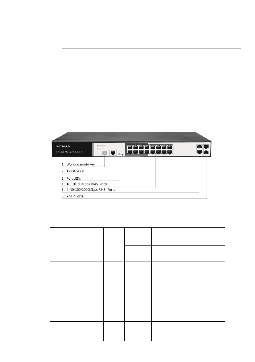
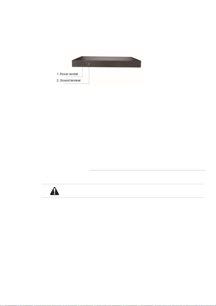
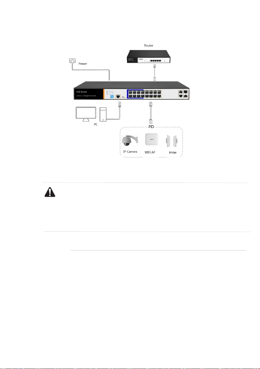
Hored PS3024S User manual

Hored
Hored IS104GS-2F User manual

Hored
Hored S5700-24G-24F-4TF User manual

Hored
Hored S5700-12G-12F User manual

Hored
Hored IS104GPS-2F User manual

Hored
Hored AI606 User manual

Hored
Hored PS3016GS User manual

Hored
Hored AI1010G-Apollo User manual

Hored
Hored S5700-24F-8G-4TF User manual

Hored
Hored AI106G-Apollo User manual

Hored
Hored AI2010GX User manual

Hored
Hored IS108S-4F User manual

Hored
Hored IS108GPS-4F User manual

Hored
Hored PS3016 User manual