AU SAE J1939 User manual

Au Group Electronics Au SAE J1939 Simulator Gen II 1.00A User Manual Rev. I
Au SAE J1939 Simulator
V1.00A
User Manual
Rev. I
Au Group Electronics
April 2022
All Copyrights are reserved by Au Group Electronics. 2007 - 2022
This document can NOT be freely distributed without written approval from Au Group Electronics

Au Group Electronics Au SAE J1939 Simulator Gen II 1.00A User Manual Rev. I
2/41
Table of Contents
CHAPTER - 1 INTRODUCTION........................................................................................................................................4
1.1 TYPICAL SAE J1939-15 NETWORK TOPOLOGY WITH AU SAE J1939 SIMULATORS...........................................................4
1.2 MAJOR HARDWARE FEATURES...........................................................................................................................................4
1.3 MAJOR OPERATING FEATURES...........................................................................................................................................7
1.4 ELEVEN EDITIONS OF AU SAE J1939 SIMULATORS ...........................................................................................................7
1.4.1 Non-Plus Editions ....................................................................................................................................................7
1.4.2 Plus Editions ............................................................................................................................................................7
1.4.3 Script Editions..........................................................................................................................................................7
1.5 BASIC FUNCTIONS OF EACH EDITION .................................................................................................................................8
1.5.1 Value Package editions:...........................................................................................................................................8
1.5.2 Engine Basic editions:..............................................................................................................................................8
1.5.3 Engine Premium editions:........................................................................................................................................8
1.5.4 Vehicle Platinum editions:.......................................................................................................................................8
1.6 LICENSE /FIRMWARE UPGRADE AND ANNUAL SUPPORT SERVICE......................................................................................8
1.7 ORDER INFORMATION.........................................................................................................................................................9
CHAPTER - 2 SUPPORTED SAE J1939 PARAMETERS..............................................................................................10
2.1 VALUE PACKAGE EDITIONS ..............................................................................................................................................10
2.2 ENGINE BASIC EDITIONS...................................................................................................................................................10
2.3 ENGINE PREMIUM EDITIONS .............................................................................................................................................10
2.4 VEHICLE PLATINUM EDITIONS..........................................................................................................................................10
CHAPTER - 3 OPERATING INSTRUCTIONS...............................................................................................................11
3.1 POWER ON........................................................................................................................................................................11
3.2 OPERATING MODE (STATIC/DYNAMIC)............................................................................................................................11
3.3 PUSH BUTTON FUNCTIONS ...............................................................................................................................................11
3.4 LED INDICATOR STATUS..................................................................................................................................................13
CHAPTER - 4 AU J1939 SIMULATOR REMOTE TERMINAL GUI..........................................................................16
4.1 CONTROL PANEL –STEP 1: CONNECT TO J1939 SIMULATOR ...........................................................................................17
4.1.1. Device Information.................................................................................................................................................17
4.1.2. CAN Baud Rate and Source Address Settings........................................................................................................17
4.2 CONTROL PANEL –STEP 2: REMOTE CONTROL AU J1939 SIMULATOR.............................................................................18
4.3 CONTROL PANEL –STEP 3: SCRIPT CONTROL ...................................................................................................................19
4.3.1 Turn On Script control...........................................................................................................................................19
4.3.2 Generate Script Command.....................................................................................................................................19
4.3.3 Script Syntax for Au J1939 Simulator....................................................................................................................20
4.3.4 Example of script command segments....................................................................................................................21
4.3.5 Run script from a file..............................................................................................................................................21
4.4 DISPLAY PANEL................................................................................................................................................................23
4.4.1. Value Package Parameters....................................................................................................................................23
4.4.2. Engine Basic Parameters.......................................................................................................................................23
4.4.3. Engine DM1...........................................................................................................................................................23
4.4.4. Engine DM2...........................................................................................................................................................25
4.4.5. Engine Configuration.............................................................................................................................................26
4.4.6. ABS DM1 and Transmission DM1.........................................................................................................................26
4.4.7. Engine / ABS / Transmission Info and Warning Lamp...........................................................................................27
CHAPTER - 5 DATA CONFIGURATION.......................................................................................................................28
5.1 WARNING SIMULATION ....................................................................................................................................................28
5.2 AU SAE J1939 SIMULATOR 1.00A SUPPORTED PGN AND SPN........................................................................................29
5.3 TRANSPORT PROTOCOL FOR DM2 REQUEST ....................................................................................................................30
5.4 SIMULATION RESULT VS.CONTROL STEP VALUE...............................................................................................................30
CHAPTER - 6 APPENDIX..................................................................................................................................................36

Au Group Electronics Au SAE J1939 Simulator Gen II 1.00A User Manual Rev. I
3/41
6.1 APPENDIX A-REMOTE TERMINAL GUI INSTALLATION GUIDE........................................................................................36
6.1.1 What is needed to install Au J1939 Simulator Remote Terminal GUI...................................................................36
6.1.2 Step by step guide on installing the software to your PC.......................................................................................36
6.2 APPENDIX B-HOW TO UPGRADE AU J1939 SIMULATOR LICENSE ...................................................................................37
6.2.1 What is needed to upgrade Au J1939 Simulator License?.....................................................................................37
6.2.2 Step by Step License Upgrading Procedure...........................................................................................................37
6.3 APPENDIX C-AU PIC SERIAL BOOT-LOADER APPLICATION NOTE..................................................................................39
6.3.1 What is needed before install Au PIC Boot-loader? ..............................................................................................39
6.3.2 How to install Au PIC Boot-loader........................................................................................................................40

Au Group Electronics Au SAE J1939 Simulator Gen II 1.00A User Manual Rev. I
4/41
Chapter - 1 Introduction
Au SAE J1939 Simulators (Gen II 1.00A), a family of well designed devices (Figure 1-1), are capable of simulating
majority of J1939 signals on a SAE J1939 network. It is widely for product development, validation, assembly-line
testing, incoming inspection, and business demonstration, etc.
Figure 1-1
1.1 Typical SAE J1939-15 Network Topology with Au SAE J1939 Simulators
A typical SAE J1939-15 network topology with an Au SAE J1939 Simulator is illustrated in Figure 1-2.
Figure 1-2
1.2 Major Hardware Features
•Power supply: +12V~+14.2 VDC nominal, 250mA max
•SAE J1939-15 Type II ECU: contain an internal 120 ohm load resistor for easy network setup
•Compact size: 4-1/8" L X 1-3/4"W X 7/8”H
•Enclosure color: Black or PC white
•Operating temperature: -4 ˚F to 185 ˚F (-20 ˚C to 85 ˚C)
•1 buzzer:
Can be muted or enabled
•9 LED indicators: Power, Range, Warning, ▼0%, 20%, 40%, 60%, 80%,▲100%

Au Group Electronics Au SAE J1939 Simulator Gen II 1.00A User Manual Rev. I
5/41
•3 push buttons: Simulated SAE J1939 signals can be adjusted by push buttons: Menu, Down, Up
•TVS (Transient Voltage Suppressor) protection on CAN bus
•1 DB9 Male "BUS" Interface: For power supply and CAN/J1939 network connection (Figure 1-3)
Figure 1-3
•1 RS232 interface: for CAN baud rate setting, Source address configuration, in-field firmware update, license
management, and computer remote control (for Plus editions and script editions) (Figure 1-4).
Figure 1-4
Au J1939 Simulator can be connected to a PC through an RS232 serial extension cable (part # CBL-RS232-01), as
shown in Figure 1-5.
Figure 1-5
For a PC with USB port, a USB to RS232 serial convert cable (part # CBL-USB-232) can be used (Figure 1-6).
Figure 1-6
The following cables and power supply are optional components for different application, they are sold separately.

Au Group Electronics Au SAE J1939 Simulator Gen II 1.00A User Manual Rev. I
6/41
Table 1-1 Necessary accessories for Au J1939 Simulator
CBL-CAN-485-01
A 6-wire color-coded cable used for Au J1939 and Au J1708 devices. One end of the
cable is a DB9 female connector, designed to mate with Au devices on the BUS side.
The other side of the cable is a pigtail with 3 pairs of twisted color-coded wires:
Red wire: Power supply, e.g. +12V DC Black wire: Ground
Yellow wire: CAN High Green wire: CAN Low
Violet: J1708A+ Brown: J1708B-
CBL-CAN-485-02D
CBL-CAN-485-02D cable provides power supply, J1708/J1587 and CAN network
connection similar to what's available on trucks, RVs and School buses.
One end is a DB9 female connector, the other end are dual HD10 Serial 9-way SAE
compatible Receptacles (green for 500K CAN baud rate and black for 250K CAN baud
rate) . It also includes a power Supply Jacket (2.1 mm Positive center), which can
supply power to all devices connected on the cable. The cable ca be used for SAE
J1939-11, J1939-14, 250Kbps and 500Kbps networks.
PWR-912V-CP
Wall mount AC/DC power supply can supply power to all devices connected to CBL-
J1708-02 or CBL-CAN-485-02D.
zPositive center
zConnector style: 2.1mm I.D. x 5.5mm O.D. x 12mm Female (compatible
with the power jacket of CBL-J1708-02 and CBL-CAN-485-02)
zVoltage input: 110~120V AC Input
zVoltage output: 12V DC
zCurrent output: 500mA Max.
zInrush current: 40A Maximum
zPower: 6.0W
zLine Regulation: +/- 2%
zLoad Regulation: +/- 5%
CBL-RS232-01
RS232 Serial extension cable can be used to connect computer Serial port to Au
J1939 / J1708 products (on RS232 Side).
zFully shielded to prevent unwanted EMI/RFI
zFully molded connectors with thumbscrews provide a quick and easy
connection every time
zConnectors: DB9 Male to DB9 Female
zCable length: 6 feet
All 9 connector pins are wired straight through
CBL-USB-232
zThe USB to Serial Converter cable can be used to connect computer USB port to
Au J1939 / J1708 products (on RS232 Side).
zCompatible with Vista, XP, Win7, and Win10.
Three LED (Power, TX and RX) are included. Power LED is on when USB power
is supplied. TX LED will blink when COM port is transmitting. RX LED will blink
when COM port is receiving.
zCompatible with all Au Group Electronics system products, J1939 Simulators,
J1708 Simulators, FMS Simulators, NMEA2000 Simulators, J1939 /J1708
Interpreters, J1939/J1708 MCS, J1939/J1708 DCS, J1939/J1708 Gateways.

Au Group Electronics Au SAE J1939 Simulator Gen II 1.00A User Manual Rev. I
7/41
1.3 Major Operating Features
•Smart features: Recalls last operating mode at power-on, and capable of generating dynamic data.
•Easy to use: No software setup experience or CAN/J1939 protocol configuration skills are required. After a
network is connected, apply power and it will dynamically generate J1939 data when in dynamic mode.
•CAN bus on/off switch
•Configurable CAN Baud Rate: Sets CAN baud rate at 250K, 500K, 62.5K, 125K, or 1M bps
•Multiple Source Addresses to select from
•One VIN or multiple VIN switch
•Static mode or Dynamic Mode
oStatic mode output static J1939 signals, signals can be changed manually
oDynamic mode automatically change the output value of SAE J1939 signals
oTwo modes can be switched easily (via press and hold both Menu and Up buttons until a long beep is
heard)
•PC Remote Terminal GUI:
oConnects Au J1939 Simulator to a PC through serial communication.
oDisplays the simulator information, alters and displays simulator SA settings, and performs license
upgrading.
oDisplays simulated J1939 signals on a computer screen for "Plus" editions and "Script" editions.
oProvides script control capabilities for "Script" editions.
•Script control capabilities (for "Script" editions only):
oCapable of setting six parameters to any value in SAE J1939 specification allowed range, generating
script, running script file.
oThe script can be delayed, repeated, running with or without white noise.
oScript control can be turn on/off easily
oWhite noise can be turn on/off easily
•In-field license upgrade feature.
•In-field firmware update capability
•Annual support and minor upgrade services are available
•Custom firmware and GUI modification is available upon request
1.4 Eleven Editions of Au SAE J1939 Simulators
Eleven editions of Au SAE J1939 simulator 1.00A are available: 4 Non-Plus editions, 4 Plus editions, and 3 Script
editions.
1.4.1 Non-Plus Editions
Au J1939 Simulator Non-Plus editions are stand-alone devices. They can be operated independently without a PC.
Full range of J1939 signals can be generated by controlling 3 push buttons.
1.4.2 Plus Editions
Au J1939 Simulator Plus editions have all functions of Non-Plus editions, with the addition of a PC Remote
Terminal GUI. Like the Non-Plus editions, all the Plus editions can still work independently without a PC. The
"Remote Terminal GUI" connects Au J1939 Simulator to a PC through serial communication. It displays the
simulator information, alters and displays the simulator settings, and performs license upgrading for all editions. It
also shows simulated J1939 signals on a computer screen for "Plus" editions and "script" editions.
Plus Edition =Non-Plus Edition +PC Remote Terminal GUI Program
1.4.3 Script Editions
Au J1939 Simulator Script editions have all the functions of Plus editions, with the addition of script control
capabilities. Detail information can be found at chapter 4.
Script Edition =Plus Edition +Script control capabilities
•Script control sets six parameters to any value in the SAE-J1939 specification allowed range: Engine
RPM, Vehicle speed, VIN, Battery voltage, Engine hour, Total vehicle distance.
•Engine hour and Total vehicle distance can be set with initial values, then they will accumulate over time.
•Four buttons to generate frequently used script segments.
•Script control can load and run a saved script file.
•The script can be delayed and repeated with or without white noise.

Au Group Electronics Au SAE J1939 Simulator Gen II 1.00A User Manual Rev. I
8/41
•Script control can switch CAN bus on/off.
•Script control can be turned on/off with a click
•White noise can be turned on/off with a click.
1.5 Basic Functions of Each Edition
1.5.1 Value Package editions:
•"Statically" or "dynamically" generate 6 most frequently used engine parameters
•Two push buttons (Up and Down) are used in "static mode" to adjust data outputs
•In "dynamic mode", data cycles automatically in its SAE defined range
•LEDs indicate the control step value and reflect push button operations
•Buzzer sound also reflects push button inputs, and can be enabled/disabled
•"Script" control capability is NOT available for Value Package editions
1.5.2 Engine Basic editions:
•Includes all Value Package edition functions
•"Statically" or "dynamically" generate 23 most frequently used engine parameters
•"Script" control capability is available for Engine Basic Script edition
1.5.3 Engine Premium editions:
•Includes all Engine Basic edition functions
•Includes Premium features on SAE J1939 Transport Protocols:
oEngine DM1/DM2 warnings (support both single packet and multi-packets)
oEngine “Red Stop” and “Amber” lamp warnings
oEngine DM3
•"Script" control capability is available for Engine Premium Script edition
1.5.4 Vehicle Platinum editions:
•Includes all Engine Premium edition functions
•Includes Vehicle Network features (3 controller applications have been implemented):
oABS related signals
oTransmission related signals
oEngine Configurations
•"Script" control capability is available for Vehicle Platinum Script Edition
1.6 License /Firmware Upgrade and Annual Support Service
Part numbers for license upgrading and annual service for the 11 editions of Au SAE J1939 Simulator 1.00A
are summarized in Figure 1-7.
Figure 1-7

Au Group Electronics Au SAE J1939 Simulator Gen II 1.00A User Manual Rev. I
9/41
•Simulator license can be in-filed upgraded to higher editions. "Au License Management" in the remote
terminal GUI provides the in-filed license upgrading capability.
oValue Package editions can be upgraded to Engine Basic editions (part #: LICJ1939-004).
oEngine Basic editions can be upgraded to Engine Premium editions (part #: LICJ1939-001).
oEngine Premium editions can be upgraded to Vehicle Platinum editions (part #: LICJ1939-002).
o"Non-Plus” editions are able to be upgraded to plus editions (part #: LICJ1939-003).
oEngine Basic "Plus” editions and above are able to be upgraded to "Script" editions (part #:
LICJ1939-005).
•Firmware can be in-field updated with Au PIC Boot-loader
oFirmware update code or customized codes can be re-programmed to gain new or special features.
oAu J1939 Simulator 1.00A can be upgraded to Au J1939 Simulator 2.00A (part #: FIRJ1939-001)
o"Au PIC Boot-loader " provides the in-field firmware upgrading capability.
•Annually minor upgrade and support service is available (part #: SVS-SIM-J1939).
1.7 Order information
All of Au J1939 Simulators, accessories, and license upgrade are available to be ordered at the website of Au Group
Electronics: https://www.auelectronics.com/System-J1939Simulator.htm
The part# for 11 editions of Au SAE J1939 simulator are summarized in Table 1-2.
Table 1-2 Part# for eleven editions of Au SAE J1939 simulator Gen II 1.00A
Au SAE J1939 Simulators 1.00A Editions Part#
Au SAE J1939 Simulator (Value Package Non-Plus Edition) SIMJ1939-013
Au SAE J1939 Simulator (Engine Basic Non-Plus Edition) SIMJ1939-001
Au SAE J1939 Simulator (Engine Premium Non-Plus Edition) SIMJ1939-002
Non-Plus Edition
Au SAE J1939 Simulator (Vehicle Platinum Non-Plus Edition) SIMJ1939-003
Au SAE J1939 Simulator (Value Package Plus Edition) SIMJ1939-014
Au SAE J1939 Simulator (Engine Basic Plus Edition) SIMJ1939-004
Au SAE J1939 Simulator (Engine Premium Plus Edition) SIMJ1939-005
Plus Edition
Au SAE J1939 Simulator (Vehicle Platinum Plus Edition) SIMJ1939-006
Au SAE J1939 Simulator (Engine Basic Script Edition) SIMJ1939-017
Au SAE J1939 Simulator (Engine Premium Script Edition) SIMJ1939-018
Script Edition
Au SAE J1939 Simulator (Vehicle Platinum Script Edition) SIMJ1939-019
6-wire cable for power supply and J1939/J1708 network connection CBL-CAN-485-01
CAN/J1939/J1708 cable with a power jacket, a DB9 female connector,
and dual SAE 9-way Receptacles (for 500K and 250K CAN baud rate) CBL-CAN-485-02D
14V Wall mount AC/DC power supply, positive center, 110V input PWR-912V-CP
RS232 Serial Extension Cable (for computer with RS232 port) CBL-RS232-01
Accessories
USB to RS232 Serial Convert Cable (for computer with USB port ) CBL-USB-232
Service 1 year support and minor upgrades for Au SAE J1939 Simulator SVS-SIM-J1939
From Value Package Edition to Engine Basic Edition LICJ1939-004
From Engine Basic Edition to Engine Premium Edition LICJ1939-001
From Engine Premium Edition to Vehicle Platinum Edition LICJ1939-002
From Non-Plus Edition to Plus Edition LICJ1939-003
License Upgrade
From Plus Edition to Script Edition LICJ1939-005

Au Group Electronics Au SAE J1939 Simulator Gen II 1.00A User Manual Rev. I
10/41
Chapter - 2 Supported SAE J1939 Parameters
2.1 Value Package editions
Au SAE J1939 Simulator Gen II 1.00A Value Package editions supports 11 most frequently used engine parameters:
•Engine % Load at Current Speed (SPN 92)
•Engine Oil Pressure (PSI) (SPN 100)
•Engine Coolant Temperature (SPN 110)
•Engine Fuel Rate (SPN 183)
•Engine Speed (RPM) (SPN190)
•Engine Total Hours of Operation (Hr) (SPN 247) *
•Response for Engine Hour Request (Rx)
•Engine Address Claiming
•Engine Address CANNOT Claim
•Response for Address Claim Request (Rx)
•Address Conflict Response with Contention
* Response only with SAE J1939-21 Request PGN 59904.
2.2 Engine Basic editions
Au SAE J1939 Simulator Gen II 1.00A Engine Basic editions support all parameters listed with Value package
editions, plus the following 20 SAE J1939 engine parameters (total 31):
•Wheel Based Vehicle Speed (MPH) (SPN 84)
•Accelerator Pedal Position 1 (SPN 91)
•SAE J1939 Fuel Level 1 (SPN 96)
•Engine Turbocharger Boost Pressure (PSI) (SPN 102)
•Engine Intake Manifold 1 Temperature (F) (SPN 105)
•Battery Potential (Voltage), Switched (SPN 158)
•Engine Instant Fuel Economy (SPN 184)
•Engine Trip Distance (SPN 244)
•Total Vehicle Distance (SPN 245)
•Cruise Light (SPN 595)
•Engine Clock (HH:MM) (SPN 961, 960)
•Response for Engine Clock Request (Rx)
•Engine Clock setup (SPN 1605, 1604) (Rx)
•SAE J1939 Acknowledge protocol (ACK, NACK)
•Engine DM1 Red Stop Lamp OFF status (SPN 623)
•Engine DM1 Amber Lamp OFF status (SPN 624)
•Engine DM1 (Health-heart-beat)*
•Vehicle Identification Number (VIN) (SPN 237)
•Response for VIN global request
•Response for VIN specific request
•Water-in-Fuel Indicator (Health-heart-beat)* (SPN 97)
* Health-heart-beat: normal signal only, no warning, signal repeats in SAE defined “heart-beat” rate.
2.3 Engine Premium editions
Au SAE J1939 Simulator Engine Premium editions support all SAE J1939 parameters listed with Engine Basic editions,
plus the following 12 SAE J1939 parameters and new features (total 43):
•Engine DM1 Warning On/Off control
•Engine Red Stop Lamp On/Off
•Engine Amber Lamp On/Off
•Engine DM1 Single-Packet warning
•Engine DM1 Multi-Packet warnings
•Engine DM2 Single-Packet warning
•Engine DM2 Multi-Packet warnings
•Response for DM2 global request (Rx)
•Response for DM2 specific request (Rx)
•Engine DM3 and Engine DM2 On/Reset control (Rx)
•SAE J1939 TP.CM.BAM, TP.DT protocol
•SAE J1939 TP.CM.EndOfMsgAck, TP.CM.RTS,
TP.CM.CTS, TP.Conn.Abort, TP.DT protocol
2.4 Vehicle Platinum editions
Au J1939 Simulator vehicle Platinum editions support all SAE J1939 parameters listed with Engine Premium editions,
plus 40 bytes of Engine Configuration, ABS related parameters, and Transmission related parameters (total 61).
•Engine Configuration (40 bytes)
•ABS address claim
•ABS Address CANNOT Claim
•ABS Response Request for Address Claim (Rx)
•ABS address conflict Response with Contention
•ABS Red Stop Lamp On/Off
•ABS Amber Lamp On/Off
•ABS DM1 (No warning or 1 warning)
•ABS Heart-beat PGN-EBC1
•Transmission address claim
•Transmission Address CANNOT Claim
•Transmission response request for address claim(Rx)
•Transmission address conflict response with contention
•Transmission Red Stop Lamp On/Off
•Transmission Amber Lamp On/Off
•Transmission DM1 (No warning or 1 warning)
•Transmission Oil Temperature
•Transmission Heart-beat PGN-ET

Au Group Electronics Au SAE J1939 Simulator Gen II 1.00A User Manual Rev. I
Chapter - 3 Operating Instructions
All editions of Au SAE J1939 Simulator Gen II 1.00A can be operated by just controlling 3 push buttons. It generates
SAE J1939 signals for product developers, testers, operators and manufacturers.
3.1 Power On
Mate the DB9 female connector of a 6-wire cable (Part#: CBL-CAN-485-01) to the BUS side DB9 male connector of
Au SAE J1939 Simulator, connect the Red wire to +12 ~ +14.2V DC power supply, Black wire to ground, Yellow
wire to CAN-H, Green wire to CAN-L. The Power LED on simulator will light up, and the simulator will resume the
last saved operating mode (static mode or dynamic mode).
3.2 Operating Mode (Static/Dynamic)
After power on, Au SAE J1939 Simulator will work in either static mode or dynamic mode.
•Static mode: Au SAE J1939 Simulator Gen II generates steady SAE J1939 signals. In this mode, two push
buttons (Up and Down) can be used to change the data outputs. When no button is pushed, all data will
remain at the last value.
•Dynamic mode: The value of all data will change automatically every second in SAE J1939 defined range
•Switch between dynamic mode and static mode: Press and hold both Menu and Up buttons until a long
beep is heard if buzzer is enabled; or both the "▼0% LED" and "▲100% LED" flip their status (from on to
off or vice versa)
Au SAE J1939 Simulator Gen II equipped with 3 push buttons (Menu, Down, Up) and 9 LEDs (Figure 3-1). Each
LED is named after its function.
Figure 3-1
3.3 Push Button Functions
•Press Menu button:
oMenu button is used to control Warning LED on/off. A single press on Menu button will turn on the
Warning LED if the Warning LED was off, and vice versa.
oThe Menu button function is available only on Engine Premium editions and Vehicle Platinum editions.
For Value Package editions and Engine Basic editions, Menu button is not used. Warning LED will be
constant off.
oIf buzzer is enabled, a short beep will be heard upon a press on the Menu button.
In dynamic mode, the simulator automatically adjusts the control step value by itself. This will generate dynamic
J1939 signals. In static mode, all* simulated SAE J1939 signal will be controlled by the control step value, which is
still able to be manually controlled by the Up and Down buttons.
Note: * The Engine Clock is not controlled by the control step value and push buttons; it runs all by itself just like a real clock.
•Press Down button:
oDown button is used to decrease the values of all J1939 signals. A single press will decrease all data
one step from previous values until they reach the minimum values. ▼0% LED will be triggered on/off.
oIf ▼0% LED is on, press Down button one time, ▼0% LED will be off.
oIf ▼0% LED is off, press Down button one time, ▼0% LED will be on.
o80% LED blinks when control step value equals to 80%,
o60% LED blinks when control step value equals to 60%,
o40% LED blinks when control step value equals to 40%,
o20% LED blinks when control step value equals to 20%,
o▼0% LED blinks when control step equals to 0%,
oIf buzzer is enabled, a short beep will be heard upon a press on Down button.

Au Group Electronics Au SAE J1939 Simulator Gen II 1.00A User Manual Rev. I
12/41
•Press Up button:
oUp button is used to increase the values of all J1939 signal. A single press will increase all simulated
data one step to next data level until they reach the maximum values, ▲100% LED will be triggered
on or off.
oIf
▲100% LED is on, press Up button one time, ▲100% LED will be off.
oIf
▲100% LED is off, press Up button one time, ▲100% LED will be on.
o20% LED blinks when control step value equals to 20%,
o40% LED blinks when control step value equals to 40%,
o60% LED blinks when control step value equals to 60%,
o80% LED blinks when control step value equals to 80%,
o▲100% LED blinks when control step value equals to the highest value, 100%.
oIf buzzer enabled, a short beep will be heard upon a press on Up button.
•Press and hold both Down + Up button for more than 1 second:
oDown + Up buttons are used to turn buzzer on/off.
oIf buzzer is on, press and hold Down + Up for more than 1 second will silent buzzer thereafter.
oIf buzzer is mute, press and hold Down + Up for more than 1 second will enable the buzzer thereafter.
oBoth
▲100% and ▼0% LED will flip their on/off status as a visual indication of this dual-button input.
oIf buzzer is enabled, a long beep will be heard to reflect the input of Down + Up button.
•Press and hold both Menu + Down button for more than 1 second:
oMenu + Down buttons are used to turn Engine DM2 warning on/Reset.
oBoth ▲100% LED and ▼0% LED will flip their status as a visual indication of this dual-button input.
oIf buzzer is enabled, a long beep will be heard to reflect the input of Menu + Down button.
oThe Engine DM2 warning messages (on premium and platinum editions) are always on after power-on.
It can be reset when an Engine DM3 PGN is received.
oFor continuous test purpose, after an Engine DM3 PGN is received, either re-power-on the simulator
or press and hold both Menu + Down button for more than 1 second will turn on the Engine DM2
warning again.
•Press and hold both Menu + Up button:
oMenu + Up buttons are used to switch between static mode and dynamic mode.
oBoth ▲100% LED and ▼0% LED will flip their status as a visual indication of this dual-button input.
oIf buzzer enabled, a long beep will be heard to reflect the input of Menu + Up button.
•Press and hold both Menu + Up + Down button for more than 1 second:
oMenu + Up + Down buttons are used to switch CAN bus On/Off.
oIf CAN-OFF is checked, means CAN bus is off, no parameters will be transmitted by the J1939
Simulator. Three LED (▼0% LED, ▲100% LED, and Range LED) will blinking every one second.
oBoth ▲100% LED and ▼0% LED will flip their status as a visual indication of this dual-button input.
oIf buzzer enabled, a long beep will be heard to reflect the input of Menu + Up + Down button.
The push button functions are summarized in Table 3-1.
Table 3-1 Summary of Push button functions
Push Button Operation Function
Press Down button Decrease all simulated data until they reach the lowest value
Press Up button Increase all simulated data until they reach the highest value
Press Menu button DM1 Warning On/Off control (N/A for Value Package and Engine Basic editions)
Press & hold both Down + Up button Buzzer ON/OFF control
Press & hold Menu + Up button Switch between Static/Dynamic mode
Press & hold Menu + Down button Engine DM2 ON/Reset control (N/A for Value Package and Engine Basic editions)
Press & hold Menu + Up + Down button Switch On/Off CAN bus
Au Group Electronics Au SAE J1939 Simulator Gen II 1.00A User Manual Rev. I
13/41
3.4 LED Indicator Status
Note: Red LEDs and Green LEDs are used in this document for illustration purpose; actual product might have
different LED color. Same applies to the push buttons. Au Group Electronics reserve the right of changing the
color on each LEDs and push buttons without further notification.
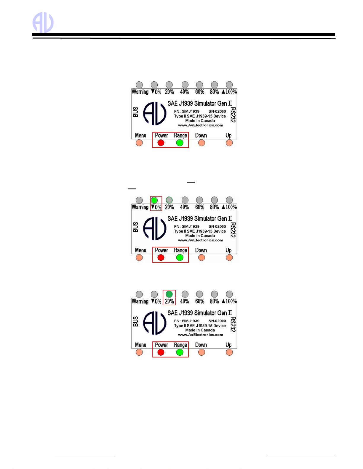
•When power on, both Power LED and Range LED lit, as shown in Figure 3-2.
Figure 3-2
All SAE J1939 data can be changed within the SAE defined range from 0 to 100 control steps (named 0% to
100% control step value from now on), 6 LEDs are used to identify the control step value in the range of 0%,
20%, 40%, 60%, 80%, and 100%.
•▲100% LED will be on or off with a press on the Up button, accompany with the increasing brightness of
Range LED. A press on the Up button will also increase the control step value and all simulated data.
oWhen control step value equals to 0%, the ▼0% LED blinks. as shown in Figure 3-3
Figure 3-3
oWhen control step value equals to 20%, 20% LED blinks.
oIf keep pressing Up button, the control step value will keep increasing. The 20% LED will then be
always on, as shown in Figure 3-4. This indicates a data range from 21- 39%.
Figure 3-4
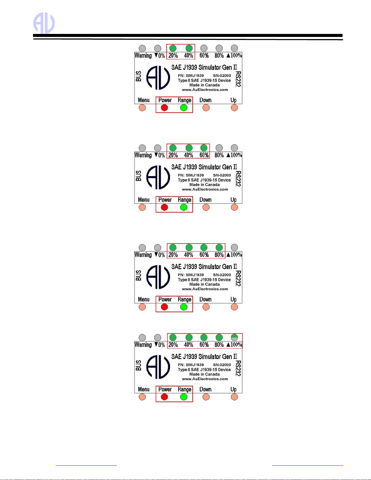
oWhen control step value equals to 40%, 40% LED blinks.
oIf keep pressing Up button, the control step value will keep rising, 20% and 40% LED will be always
on, as shown in Figure 3-5. It indicates the data range from 41% to 59%.
Au Group Electronics Au SAE J1939 Simulator Gen II 1.00A User Manual Rev. I
14/41
Figure 3-5
oWhen control step value equals to 60%, 60% LED blinks
oIf keep pressing Up button, the control step value will keep rising, the 20%, 40%, and 60% LED will
be on, as shown in Figure 3-6, it indicates the data range from 61% to 79%.
Figure 3-6
oWhen control step value equals to 80%, 80% LED blinks.
oIf keep pressing Up button, the control step value will keep rising, 20%, 40%, 60%, and 80% LED will
be on, as shown in Figure 3-7, it indicates the data range from 81% to 99%.
Figure 3-7
oWhen control step value equals to 100%, 20%, 40%, 60%, and 80% LED will be constant on. ▲100%
LED blinks, as shown in Figure 3-8.
Figure 3-8
•▼0% LED will be on or off when pressing Down button, accompany with the decreasing brightness of Range
LED. A press on the Down button will also decrease the control step value and all simulated data. When the
control step value equals to 0%, ▼0% LED blinks.
•When CAN bus is off, three LED (▼0% LED, ▲100% LED, and Range LED) blinks, as shown in Figure 3-9.

Au Group Electronics Au SAE J1939 Simulator Gen II 1.00A User Manual Rev. I
15/41
Figure 3-9
The control step value LED indicator status is summarized in Table 3-2.
Table 3-2 Control step value vs. LED indicator status (in Static Mode)
Step Operation LED Status
1 Connect +12~+14.2 V DC power supply Power, Range LED on, the rest LED will recall the last
saved status in Static mode
2 Press Down button ▼0% LED on/off
3 Continue press Down button until the control step = 0% ▼0% LED blink
4 Press Up button ▲100% LED on/off
5 Continue press Up button for control step from 1 to 19% Power, Range LED constant on
6 Continue press Up button for control step = 20% Power, Range LED on, 20% LED Blink
7 Continue press Up button for control step from 21 to 39% Power, Range LED on, 20% LED on
8 Continue press Up button for control step = 40% Power, Range, 20% LED ON, 40% LED Blink
9 Continue press Up button for control step from 41 to 59% Power, Range, 20%, 40% LED on
10 Continue press Up button for control step = 60% Power, Range, 20%, 40% LED on, 60% LED blink
11 Continue press Up button for control step from 61 to 79% Power, Range, 20%, 40%, 60% LED on
12 Continue press Up button for control step = 80% Power, Range, 20%,40%, 60% LED on, 80% LED blink
13 Continue press Up button for control step from 81 to 99% Power, Range, 20%, 40%, 60%, 80% LED on
14 Continue press Up button for control step = 100% Power, Range, 20%, 40%, 60%, 80% LED on, ▲100%
blink
15 Press & hold Menu + Up + Down to switch CAN bus on/off ▼0%, ▲100%, Range LED blink

Au Group Electronics Au SAE J1939 Simulator Gen II 1.00A User Manual Rev. I
16/41
Chapter - 4 Au J1939 Simulator Remote Terminal GUI
The Remote Terminal Graphic User Interface(GUI) includes a control panel and a display panel. The control panel
is located on the left side, while the display panel is located on the right side. The display panel is applicable only for
“Plus” editions and “Script” editions of Au SAE J1939 Simulator. It displays engine, ABS, Transmission information,
warning lamp, etc. Figure 4-1 shows Remote Terminal GUI for Au SAE J1939 Simulator Gen II 1.00A vehicle
platinum script edition. All features are active.
Figure 4-1
Au J1939 Simulator Remote Terminal structure is summarized in Figure 4-2.
Figure 4-2
Following paragraphs will explain Au J1939 Simulator 1.00A remote terminal GUI in details.

Au Group Electronics Au SAE J1939 Simulator Gen II 1.00A User Manual Rev. I
17/41
4.1 Control Panel – Step 1: Connect to J1939 Simulator
Typical connection of Au J1939 Simulator in a J1939 network is illustrated in Chapter 1, Figure 1-3.
zConnect the simulator to power supply and a CAN network, and then connect it to PC serial port.
zSelect correct serial port from the “Port” drop down list, click “Connect” button.
Product information about the connected J1939 simulator, such as Product ID, FW version, Serial Number, CAN
Baud Rate, FW Build number, and Source addresses will show up, 1-VIN switch, CAN-OFF switch, and Source
Address settings will recall the last saved status, as shown in Figure 4-3.
Figure 4-3
Note: Control panel step 1 is available for all editions of Au J1939 simulator (non-plus, plus and script editions).
4.1.1. Device Information
The function of step 1 control items is summarized in Table 4-1
Table 4-1 Function summary of step 1 control items
Items Function
Port Serial port can be selected from drop down list (COM1 to COM16)
Connect Click “Connect” button to connect J1939 simulator with selected PC serial port.
Disconnect Click “Disconnect” button to release the selected PC serial port.
Exit Click “Exit” button to close the J1939 remote terminal GUI
Product ID Display the current edition of J1939 simulator (Vehicle Platinum non-plus Edition)
FW Version Display the current version of J1939 simulator that’s hooked up with the serial port. (0.1I)
Serial Number Display the serial number of J1939 simulator that’s connected to the serial port. (SN = 1939)
FW Build Number Display the firmware build number. (FW is APR 17 2022-15:26:18)
1-VIN If checked, VIN will be a fixed VIN, if unchecked, VIN changes as control step changes.
CAN-OFF If checked, CAN bus will be turned off, Script command "AT CANBUS=0"
if unchecked, CAN bus will be turned on. Script command "AT CANBUS=1"
4.1.2. CAN Baud Rate and Source Address Settings
•Default CAN baud rate is 250K bps, other CAN baud rate can be selected from the drop-down list.
•Default engine source address is 0, other engine source addressees can be selected from the drop-down list.
•Default transmission source address is 3, other engine source addressees can be selected from the drop-down
list.
•Default ABS source address is 11, other engine source addressees can be selected from the drop-down list.

Au Group Electronics Au SAE J1939 Simulator Gen II 1.00A User Manual Rev. I
18/41
Table 4-2 Au J1939 Simulator CAN Baud rate and Source Address Settings
CAN Baud Rate Engine Source Address Trans. Source Address ABS Source Address
Au J1939 simulator can
be configured to one of
the following 5 CAN Baud
Rate:
62.5K bps
125K bps
250K bps
500K bps
1M bps
8 Engine SA are available
to choose from:
0 - Engine #1
1 - Engine #2
239 -Marine Engine #3
240 -Marine Engine #4
241 -Marine Engine #5
231 -Industrial Engine #3
232 -Industrial Engine #4
233 -Industrial Engine #5
8 transmission SA are
available to choose from:
3 - Transmission #1
4 - Transmission #2
9 ABS SA are available to
choose from:
11 - System Controller
12 - Steer Axle
13 - Drive Axle #1
14 - Drive Axle #2
202-Trailer #1 Brakes
194-Trailer #2 Brakes
186-Trailer #3 Brakes
178-Trailer #4 Brakes
170-Trailer #5 Brakes
4.2 Control Panel – Step 2: Remote control Au J1939 Simulator
Remote control includes 1 scale bar, 3 push buttons (Menu, Down, Up), and 4 check boxes (Dynamic, Quite,
Warnings, Reset Eng DM2), as shown in Figure 4-4. These tools are able to remote control the output/simulated
signal of the Au J1939 Simulator Plus editions and Script editions from a PC. Note: The "Warning" Check box and
the "Menu" push button are not applicable in Value Package edition(s) and Engine Basic edition(s).
Figure 4-4
The scale bar represents the control step values from 0 to 100. The sliding action can be made by 4 methods:
keyboard, mouse or Down/Up buttons from remote terminal, or the Down/Up push button on the device. They are
summarized in Table 4-3
Table 4-3 Control Methods for Slide Bar
Action Function
Left Click Left click bring the slide to the desire location
Mouse Drag Click and hold left button drag the slide to desire location
▲or ►Increase the scale range in 1 interval
▼or ◄Decrease the scale range in 1 interval
Pg Up Increase the scale range in 10 interval
Keyboard
Pg Dn Decrease the scale range in 10 interval
Down button Decrease the scale range in 1 interval
Remote terminal /
Device Up button Increase the scale range in 1 interval

Au Group Electronics Au SAE J1939 Simulator Gen II 1.00A User Manual Rev. I
19/41
The function for the 3 push buttons and 4 check boxes is listed in Table 4-4.
Table 4-4 Functions for push button and check boxes in step 2
Tool Function
Menu Turn on/off warning (see note below)
Down Decrease the control step value in 1
Button
Up Increase the control step value in 1
Dynamic Switch between dynamic mode / static mode
Quite Turn on/off buzzer
Warning Turn on/off Eng/ABS/Trans DM1 warnings
Check box
Reset Eng DM2 Turn on/reset all Engine DM2 code
Note: Menu button is active only in the Engine Premium Plus / Script edition and Vehicle Platinum Plus / Script edition.
4.3 Control Panel – Step 3: Script control
4.3.1 Turn On Script control
•Script control capabilities are available for 3 script editions only: Engine Basic Script Edition, Engine Premium
Script Edition, Vehicle Platinum Script Edition.
•When Script control is available, it can be switched on/off. When script control is not available or is turned off,
all supported J1939 parameters are controlled by the step value.
•When script control is turned on, six J1939 parameters will be controlled by the input value of script control, all
the other J1939 parameters will still be controlled by step value.
Table 4-5 Script Control
Script control is not available Script control is turned off Script control is turned on
All parameters controlled by step
control
All parameters controlled by step
control
6 parameters controlled by Script
control inputs, all other parameters
controlled by step control
4.3.2 Generate Script Command
zWhen script control is enabled, 6 parameters will
be controlled by script control, the maximum
allowed values will be showing in its input area
respectively.
zClick "Clear All" button will clear all values in the
input area, it has no effect on the simulator .
zChange the inputs to a desire value.
zClick "Verify & Send" button, script command will be
send to J1939 Simulator, those value change will
be reflected on the display panel.
zScript command can be copied as part of a script
file, which can be saved and run at later time.
Figure 4-5

Au Group Electronics Au SAE J1939 Simulator Gen II 1.00A User Manual Rev. I
20/41
Figure 4-6
Input value of each parameters must be valid within the following range, it will be verified and send when "Verify &
Send" button is clicked. If no desire to change a particular parameter, just leave the input area blank.
Table 4-6 Valid input values of script controlled parameters
Script Controlled Parameters Min. Input Value Max. Input Value
VIN VIN must consist of 17 digits and followed by a "*" delimiter.
Engine RPM 0 8031.875
Engine Hour (hours) 0 210554060.75
MPH (mile/hour) 0 155.962
TVD (Total Vehicle Distance) (miles) 0 327080569.4
Voltage (volts) 0 3212.75
Delay (seconds) 1 86400 (24 hours)
•Delay is the time that specify how many seconds to wait before running another script command. If delay time is
not set, all script commands will run once and then remain at those values except for Engine Hour and TVD..
•The input of Engine hour and Total vehicle distance will change their initial values, both Engine Hour and Total
Vehicle Distance will accumulate over time.
4.3.3 Script Syntax for Au J1939 Simulator
•Each line of script end with \r\n,
•All line comments are preceded by a semicolon (;)
•Always use the script commands generated by Au J1939 Simulator Script generator as any other script may not
work properly. For example, the script generated from Au J1708 Simulator will not work for Au J1939 Simulator
and vice versa.
Table 4-7 Script Syntax for Au J1939 Simulator
Keyword Script command Syntax and Format Example
; Line comment are preceded by a semicolon (;) ;Cranking Profile
AT CANBUS=0
CANBUS CAN bus on/off control
0: CAN bus is off, 1: CAN bus is on AT CANBUS=1
AT WHITENOISE=0
WHITENOISE White noise on/off control
0: white noise is off, 1: white noise is on AT WHITENOISE=1
RPM AT RPM=aabbefn\r\n - script command to set Engine Speed AT RPM=3F70F3
MPH AT MPH=aabbef\r\n - script command to set Vehicle Speed AT MPH=337F64
VOLT AT VOLT=aabbef\r\n - script command to set Battery voltage AT VOLT=00FC0E
TVD AT TVD=aabbccddef\r\n - command to set Total vehicle Distance AT TVD=000065B128
HR AT HR=aabbccddef\r\n - script command to set Engine Hour AT HR=000075305E
VIN AT VIN=abcd... - script command to set VIN (17 characters with a *) AT VIN=1M8GDM9A8KP042000*6F
DELAY DELAY(t) -- The last status will stay unchanged for t seconds DELAY(1)
REPEAT REPEAT(n){ ...}
The script commands enclosed between a pair of bracelets will repeat
for n times, Repeat feature can be nested up to 10 levels
REPEAT(5){
... ...
}
Other manuals for SAE J1939
2
This manual suits for next models
11
Table of contents
Other AU Switch manuals


Popular Switch manuals by other brands

SMC Networks
SMC Networks 6624FMSC - annexe 1 installation guide

Ablerex
Ablerex ATS-16A user manual

HP
HP 316095-B21 - StorageWorks Edge Switch 2/24 release note

Büttner Elektronik
Büttner Elektronik MT NU 3600 instruction manual

Jlinks
Jlinks HDMI-SW301 operating instructions

FS
FS S1900-16T quick start guide


