AuCom EMX3-0053B User manual

USER MANUAL
MODBUS TCP INTERFACE
RIGHT FROM
THE START
Modbus TCP Interface | Rev D 3/2019
Contents
1. Warnings.............................................................................................. 2
2. Important User Information................................................................ 2
3. Installation........................................................................................... 3
4. Device Configuration ........................................................................... 6
5. PLC Configuration ............................................................................... 8
6. Feedback LEDs.................................................................................... 8
7. Operation ............................................................................................. 9
8. Modbus Registers.............................................................................. 10
9. Network Design................................................................................. 21
10. Specifications .................................................................................... 23
Product Compatibility
The Modbus TCP Interface is compatible with the following AuCom soft starters:
•CSX – 24 VAC/VDC and 110/240 VAC control voltage.
The Modbus TCP Interface is not suitable for use with CSX starters using 380/440
VAC control voltage.
•EMX3 – all models.
•MV – all models.
Disclaimer
The examples and diagrams in this manual are included solely for illustrative
purposes. The information contained in this manual is subject to change at any time
and without prior notice. In no event will responsibility or liability be accepted for
direct, indirect or consequential damages resulting from the use or application of this
equipment.
© 2019 AuCom Electronics Ltd. All Rights Reserved.

USER MANUAL
2Modbus TCP Interface (710-14812-00D)
1. Warnings
WARNING
For your safety, isolate the soft starter completely from mains voltage before
attaching or removing accessories.
WARNING
Observe all necessary safety precautions when controlling the soft starter
remotely. Alert personnel that machinery may start without warning.
2. Important User Information
2.1 Safety
It is the installer's responsibility to follow all instructions in this manual and to follow
correct electrical practice.
Close attention is required to the electrical installation and the system design to avoid
hazards either in normal operation or in the event of equipment malfunction. System
design, installation, commissioning and maintenance must be carried out by personnel
who have the necessary training and experience. They must read this safety
information and this guide carefully.
2.2 Product Design
The Modbus TCP Interface allows the soft starter to connect to an Ethernet network
and be controlled or monitored using an Ethernet communication model.
Familiarity with Ethernet protocols and networks is required to operate the device
successfully. For difficulties using this device with third party products, including
PLCs, scanners and commissioning tools, contact the relevant supplier.
USER MANUAL
Modbus TCP Interface (710-14812-00D) 3
3. Installation
CAUTION
Remove mains and control voltage from the soft starter before attaching or
removing accessories. Failure to do so may damage the equipment.
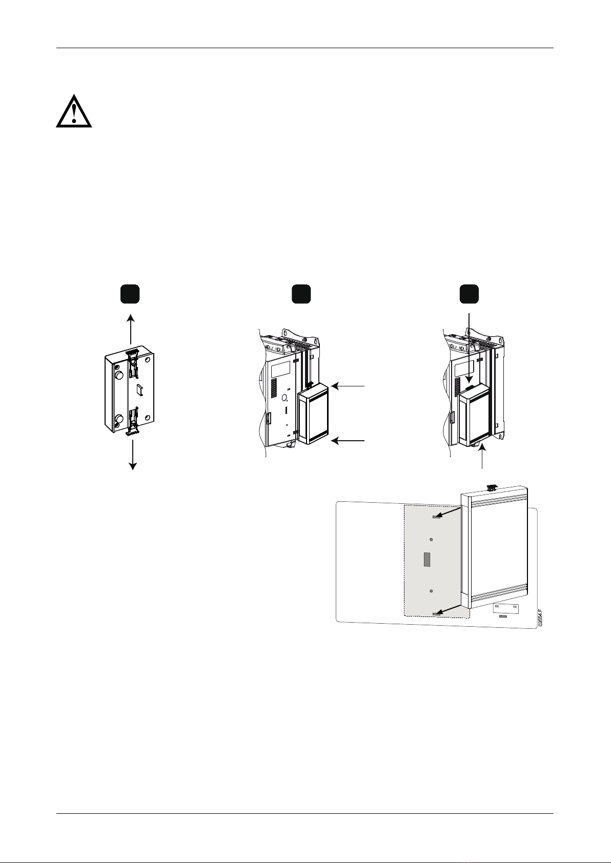
3.1 Installation Procedure
1. Remove control power and mains supply from the soft starter.
2. Fully pull out the top and bottom retaining clips on the interface. [A]
3. Line up the interface with the comms port slot. [B]
4. Push in the top and bottom retaining clips to secure the interface to the starter. [C]
5. Connect Ethernet Port 1 or Port 2 on the Modbus TCP Interface to the network.
6. Apply control power to the soft starter.
ABC
10178.C
MV:
Plug the interface onto the back of the
controller.

USER MANUAL
4Modbus TCP Interface (710-14812-00D)
To remove the interface:
1. Remove control power and mains supply from the soft
starter.
2. Disconnect all external wiring from the interface.
3. Fully pull out the top and bottom retaining clips on the
interface. [A]
4. Pull the interface away from the soft starter.
03550.C
A
3.2 Soft Starter Connection
The device is powered from the soft starter.
CSX: For the Modbus TCP Interface to accept fieldbus commands, a link must be fitted
across terminals A1-02 on the soft starter.
The Modbus TCP Interface is not suitable for use with CSX starters using
380/440 VAC control voltage.
EMX3 and MV: Input links are required across the stop and reset inputs if the soft
starter is being operated in Remote mode. In Local mode, links are not required.
NOTE
EMX3 and MV: Control via the fieldbus communication network is always
enabled in local control mode, and can be enabled or disabled in remote
control mode (parameter 6R
Comms in Remote
). Refer to the soft starter user
manual for parameter details.
CSX
EMX3 or MV
14698.A
1
3
2
1
Soft starter
1
Soft starter (remote mode)
A1, 02: Stop input
C31, C32: Stop input
C41, C42: Reset input
2
Modbus TCP Interface
2
Modbus TCP Interface
3
RJ45 Ethernet ports
3
RJ45 Ethernet ports
14699.A
1
3
2

USER MANUAL
Modbus TCP Interface (710-14812-00D) 5
3.3 Network Connection
Ethernet Ports
The device has two Ethernet ports. If only one connection is required, either port can
be used.
Cables
Use Category 5, 5e, 6 or 6e cable to connect to the device.
EMC Precautions
To minimise electromagnetic interference, Ethernet cables should be separated from
motor and mains cables by 200 mm.
If the Ethernet cable must cross motor or mains cables, the crossing should be at an
angle of 90°.
3.4 Network Establishment
The controller must establish communications directly with each device before the
device can participate in the network.
3.5 Addressing
Each device in a network is addressed using a MAC address and an IP address.
•The device can be assigned a static IP address during configuration, or can be
configured to accept a dynamic IP address (via DHCP).
•The MAC address is fixed within the device and is printed on a label on the front of
the device.

USER MANUAL
6Modbus TCP Interface (710-14812-00D)
4. Device Configuration
NOTE
The Error LED flashes whenever the device is receiving power but is not
connected to a network. The Error LED will flash occasionally during the
configuration process.
4.1 Overview
The Modbus TCP Interface is configured with a static IP address as default. To avoid IP
address conflicts and to ensure successful deployment, we recommend that the device
is connected directly to a PC or laptop to configure the IP address, before connecting
to the network.
4.2 Configuration Methods
•Ethernet attributes can be configured directly in the device using the on-board web
server. The default address for a new Modbus TCP Interface is 192.168.0.1. The
default subnet mask is 255.255.255.0. The web server will only accept connections
from within the same subnet domain.
Changes made via the on-board web server are stored permanently in the device.
•If the subnet domain of the device is different from the controller, or if the IP
address has been changed and is no longer known, use the Ethernet Device
Configuration Tool to scan the network and identify the device. Changes made via
the Ethernet Device Configuration Tool cannot be stored permanently in the device
and will be lost when control power is cycled.
4.3 On-board Web Server
To configure settings using the on-board web server, the module must be installed on
a soft starter, control power must be available, and the device and computer must be
connected to each other or to the same Ethernet network.
To configure the device using the on-board web server:
1. Start a browser on the PC and enter the device address, followed by /ipconfig.
The default address for a new Modbus TCP Interface is 192.168.0.1.
USER MANUAL
Modbus TCP Interface (710-14812-00D) 7
2. Edit the settings as required. Click "Submit" to save the new settings. To store the
settings permanently in the device, tick "Static".
3. If prompted to enter a username and password:
username: admin
password: admin
NOTE
If you change the IP address and lose your record of it, use the Ethernet Device
Configuration Tool to scan the network and identify the interface.
NOTE
If you change the subnet mask, the web server will not be able to communicate
with the device after the new settings are saved.
4.4 Ethernet Device Configuration Tool
Use the Ethernet Device Configuration Tool to connect to the device if you do not know
the IP address, or if the subnet mask of the web server does not match.
To configure settings using the Ethernet Device Configuration Tool, the device must be
installed in a soft starter, control power must be available, and the device and PC must
both be connected to the Ethernet network.
The Ethernet Device Configuration Tool can be downloaded from www.aucom.com.
NOTE
If your PC has a firewall enabled, you must add the tool to the list of authorised
programs.
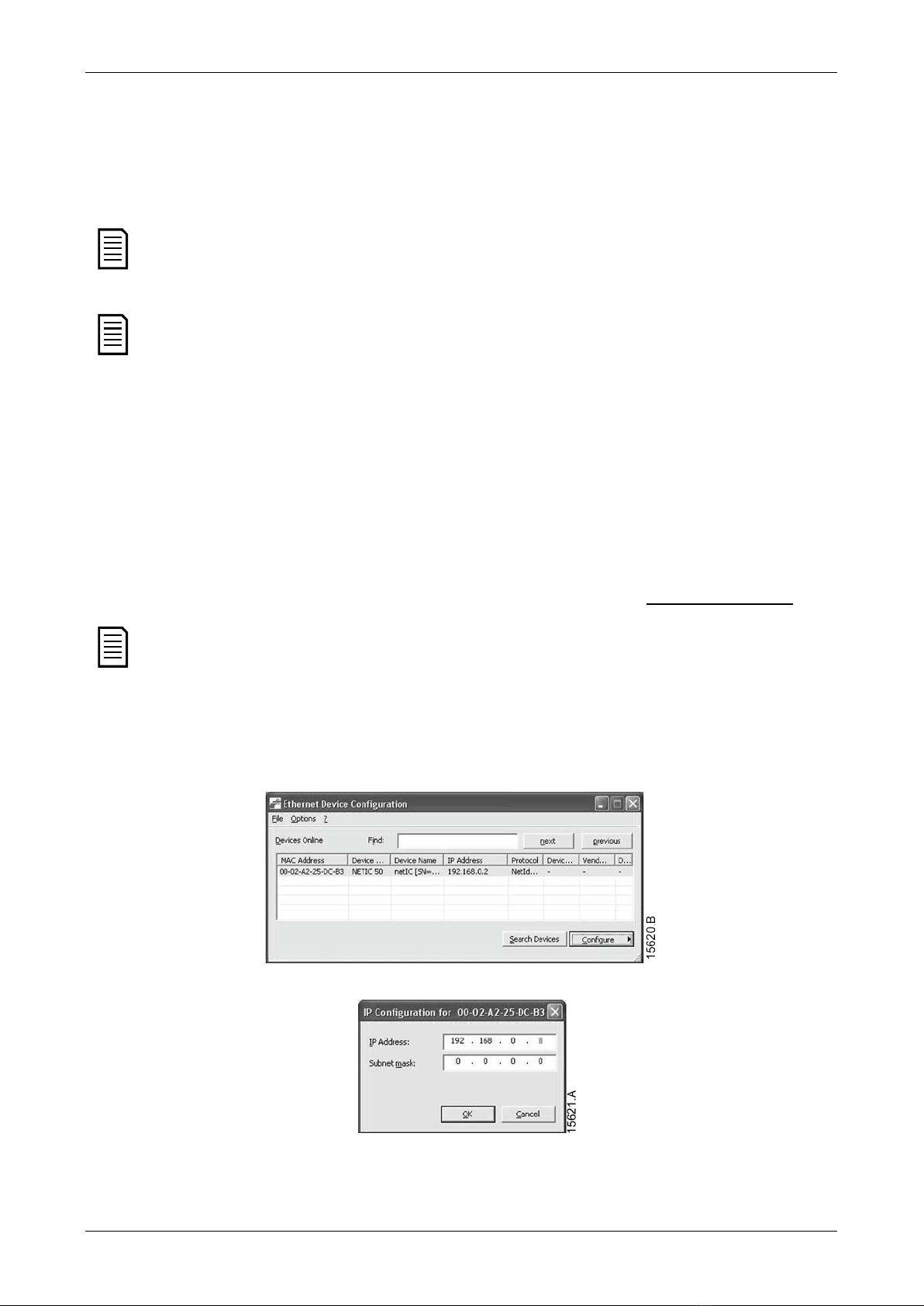
To configure the device using the Ethernet Device Configuration Tool:
1. Start the Ethernet Device Configuration Tool.
2. Click on Search Devices. The software will search for connected devices.
3. To set a static IP address, click Configure then select Set IP address.
USER MANUAL
8Modbus TCP Interface (710-14812-00D)
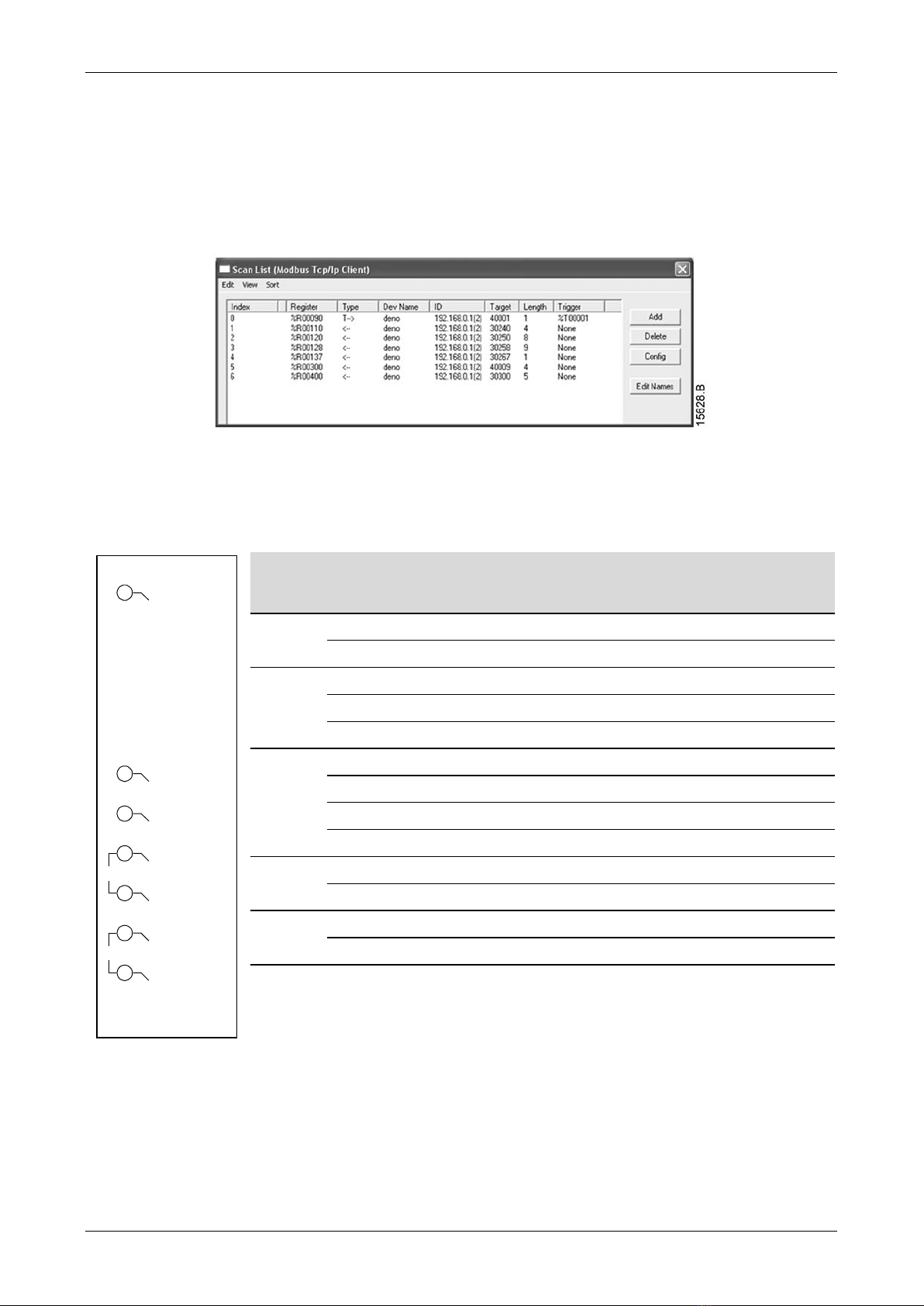
5. PLC Configuration
The PLC must be configured to map registers within the interface to addresses within
the PLC.
Example mapping of PLC registers to registers within the Modbus TCP Interface
(Target):
The device must be configured directly in the PLC. No additional files are required.
6. Feedback LEDs
1 2
TX/RX 2
TX/RX 1
Link 2
Link 1
Error
Status
Power
14702.B
LED
name
LED
Status
Description
Power
Off
Device is not powered up.
On Device is receiving power.
Error
Off
No error.
Flashing
System error.
On
Communication error.
Status
Off
Not ready.
Slow flash Ready but not configured.
Fast flash
Configured and waiting for communication.
On Communication has been established.
Link x
Off
No network connection.
On
Connected to a network.
TX/RX x
Flashing
Establishing connection.
On
Operating normally.

USER MANUAL
Modbus TCP Interface (710-14812-00D) 9
7. Operation
The Modbus TCP Interface must be controlled by a Modbus client (such as a PLC)
which complies with the Modbus Protocol Specification. For successful operation, the
client must also support all functions and interfaces described in this document.
7.1 Device Classification
The Modbus TCP Interface is a Modbus server and must be managed by a Modbus
client over Ethernet.
7.2 Ensuring Safe and Successful Control
Data written to the device will remain in its registers until the data is overwritten or
the device is reinitialised. The device will not transfer successive duplicate commands
to the soft starter.
•If the soft starter is started via fieldbus communications but stopped via the keypad
or a remote input, an identical start command cannot be used to restart the starter.
•If the soft starter may also be controlled via the keypad or the remote inputs (as
well as via fieldbus communications), a control command should be immediately
followed by a status query to confirm the command has been actioned.

USER MANUAL
10 Modbus TCP Interface (710-14812-00D)
8. Modbus Registers
NOTE
The available features and parameter details may vary according to the model
and software version of the starter. Refer to the soft starter user manual for
details of parameters and supported features.
NOTE
All references to registers mean the registers within the interface unless
otherwise stated.
8.1 Compatibility
The Modbus TCP Interface supports two modes of operation.
•In Standard Mode, the interface uses registers defined in the Modbus Protocol
Specification.
•In Legacy Mode, the interface uses the same registers as AuCom's Modbus
Interface. Some registers differ from those specified in the Modbus Protocol
Specification.
The mode of operation is determined by the values of bit 15 in register 40001.
•Standard Mode: set Bit 15 = 1. Bits 0~7 of register 40001 are used for command.
•Legacy Mode: set Bit 15 = 0. The remaining bits of register 40001 are reserved.
Examples
10000000 00000001 = start the motor (Standard Mode).
10000000 00000000 = stop the motor (Standard Mode).
00000000 xxxxxxxx = switch to Legacy Mode. The interface will ignore the remaining
bits in register 40001 and will check the value in register 40002.
8.2 Parameter Management
Parameters can be read from and written to the starter. When writing parameters to
the soft starter, every parameter will be updated to match the values in the PLC.
CAUTION
Do not change the default values of the Factory parameters (parameter group
20). Changing these values may cause unpredictable behaviour in the soft
starter.

USER MANUAL
Modbus TCP Interface (710-14812-00D) 11
8.3 Standard Mode
Command and Configuration Registers (Read/Write)
Register
Description
Bits
Details
40001
Command
(single write)
0 to 7
To send a command to the starter, write the
required value:
00000000 = Stop
00000001 = Start
00000010 = Reset
00000100 = Quick stop (coast to stop)
00001000 = Forced communication trip
00010000 = Start using Parameter Set 11
00100000 = Start using Parameter Set 21
01000000 = Local control
10000000 = Remote control
8 to 14
Reserved
15
Must = 1
40002
Reserved
40003
Reserved
40004
Reserved
40005
Reserved
40006
Reserved
40007
Reserved
40008
Reserved
40009
2
Parameter
management
(single/multiple
read or multiple
write)
0 to 15
Manage soft starter programmable parameters
1Ensure that the programmable input is not set to Motor Set Select before using this
function.
2Refer to the relevant soft starter literature for a complete parameter list. The first
product parameter is always allocated to register 40009. The last product parameter is
allocated to register 40XXX, where XXX = 008 plus total number of available
parameters in the product. The Modbus TCP protocol limits read/write operations to a
maximum of 123 registers at one time. The registers must be consecutive. These
registers support multiple write (Modbus function code 16). Attempting to write to a
single register will return an error code 01 (Illegal function code).

USER MANUAL
12 Modbus TCP Interface (710-14812-00D)
Status Reporting Registers (Read Only)
NOTE
For models EMX3-0053B and smaller, current reported via communications is
10 times greater than the actual value (displayed on the keypad).
Register
Description
Bits
Details
30240 Starter state 0 to 3 1 = Ready
2 = Starting
3 = Running
4 = Stopping (including braking)
5 = Restart delay (including temperature
check)
6 = Tripped
7 = Programming mode
8 = Jog forward
9 = Jog reverse
4
1 = Positive phase sequence
(only valid if bit 6 = 1)
5
1 = Current exceeds FLC
6
0 = Uninitialised
1 = Initialised
7 to 15
Reserved
30241
Trip code
0 to 7
Refer to
Trip Codes
on page 19.
8 to 15
Reserved
30242
Motor current
0 to 7
Average 3-phase motor current (A)
8 to 15
Reserved
30243 Motor
temperature
0 to 7 Motor 1 thermal model (%)
8 to 15
Reserved
30244 ~
30249
Reserved
30250
Version
0 to 5
Reserved
6 to 8
Product parameter list version
9 to 15 Product type code:
4 = CSX
6 = EMX3
11 = MV
30251 Model number 0 to 7
Reserved
8 to 15
Soft starter model ID
30252
Reserved
30253
Reserved

USER MANUAL
Modbus TCP Interface (710-14812-00D) 13
Register
Description
Bits
Details
30254
Starter state
0 to 4
0 =
Reserved
1 = Ready
2 = Starting
3 = Running
4 = Stopping
5 = Not ready (restart delay, restart
temperature check, run simulation)
6 = Tripped
7 = Programming mode
8 = Jog forward
9 = Jog reverse
5 1 = Warning
6 0 = Uninitialised
1 = Initialised
7 0 = Local control
1 = Remote control
8
Reserved
9 0 = Negative phase sequence
1 = Positive phase sequence
10 to 15 Refer to
Trip Codes
on page 19.
30255
Current
0 to 13
Average rms current across all three phases
14 to 15
Reserved
30256
Current
0 to 9
Current (% motor FLC)
10 to 15
Reserved
30257 Motor
temperature
0 to 7 Motor 1 thermal model (%)
8 to 15
Motor 2 thermal model (%)
30258 Power 0 to 11 Power
12 to 13
Power scale
0 = Multiply power by 10 to get W
1 = Multiply power by 100 to get W
2 = Power (kW)
3 = Multiply power by 10 to get kW
14 to 15
Reserved
30259
% Power factor
0 to 7
100% = power factor of 1
8 to 15
Reserved
30260 Voltage 0 to 13 Average rms voltage across all three phases
(medium voltage products only)
14 to 15
Reserved
30261 Current 0 to 13 Phase 1 current (rms)
14 to 15
Reserved

USER MANUAL
14 Modbus TCP Interface (710-14812-00D)
Register
Description
Bits
Details
30262 Current 0 to 13 Phase 2 current (rms)
14 to 15
Reserved
30263 Current
0 to 13
Phase 3 current (rms)
14 to 15
Reserved
30264
Voltage
0 to 013
Phase 1 voltage, rms
(medium voltage products only)
14 to 15
Reserved
30265 Voltage 0 to 13
Phase 2 voltage, rms
(medium voltage products only)
14 to 15
Reserved
30266 Voltage 0 to 13
Phase 3 voltage, rms
(medium voltage products only)
14 to 15
Reserved
30267
Parameter list
version number
0 to 7
Parameter list minor revision
8 to 15
Parameter list major version
30268 Digital input
state
0 to 15 For all inputs, 0 = open, 1 = closed (shorted)
0 = Start
1 = Stop
2 = Reset
3 = Input A
4 = Input B
5 = Input C, if fitted
6 = Input D, if fitted
7 to 15 =
Reserved
30269~
30281
Reserved

USER MANUAL
Modbus TCP Interface (710-14812-00D) 15
8.4 Legacy Mode
Registers
NOTE
For models EMX3-0053B and smaller, current reported via communications is
10 times greater than the actual value (displayed on the keypad).
NOTE
Legacy Mode reports read-only status information in registers 40003 onwards,
to match the register definitions of the clip-on Modbus Module for use with
older soft starters. Identical data is also available via registers 30003 onwards.
Register
Description
Bits
Details
40001
Reserved
0 to 14
Reserved
15
Must be zero
40002
Command
(single write)
0 to 2
To send a command to the starter, write the
required value:
1 = Start
2 = Stop
3 = Reset
4 = Quick stop (coast to stop)
5 = Forced communication trip
6 = Start using Parameter Set 1
7 = Start using Parameter Set 2
3 to 15
Reserved
40003
Starter state
0 to 3
1 = Ready
2 = Starting
3 = Running
4=Stopping (including braking)
5 = Restart delay (including temperature
check)
6 = Tripped
7 = Programming mode
8 = Jog forward
9 = Jog reverse
4
1 = Positive phase sequence
(only valid if bit 6 = 1)
5 1 = Current exceeds FLC
6
0 = Uninitialised
1 = Initialised
7 to 15
Reserved
40004
Trip code
0 to 7
Refer to
Trip Codes
on page 19.
8 to 15
Reserved

USER MANUAL
16 Modbus TCP Interface (710-14812-00D)
Register
Description
Bits
Details
40005
Motor current
0 to 7
Average 3-phase motor current (A)
8 to 15
Reserved
40006 Motor temperature 0 to 7 Motor 1 thermal model (%)
8 to 15
Reserved
40007
Reserved
40008
Reserved
40009
1
~
40200
Parameter
management
(single/multiple
read or multiple
write)
0 to 7
Manage soft starter programmable
parameters
8 to 15
Reserved
40600
Version
0 to 5
Binary protocol version
6 to 8 Parameter list version number
9 to 15
Product type code:
4 = CSX
6 = EMX3
11 = MV
40601
Reserved
40602
Reserved
40603
Reserved
40604 Starter state 0 to 4 0 =
Reserved
1 = Ready
2 = Starting
3 = Running
4 = Stopping
5 = Not ready (restart delay, restart
temperature check, run simulation)
6 = Tripped
7 = Programming mode
8 = Jog forward
9 = Jog reverse
5
1 = Warning
6
0 = Uninitialised
1 = Initialised
7
Local/Remote
0 = Local control
1 = Remote control
8
Reserved
9 0 = Negative phase sequence
1 = Positive phase sequence
10 to 15
Reserved

USER MANUAL
Modbus TCP Interface (710-14812-00D) 17
Register
Description
Bits
Details
40605
Current
0 to 13
Average rms current across all three phases
14 to 15
Reserved
40606 Current 0 to 9 Current (% motor FLC)
10 to 15
Reserved
40607 Motor temperature 0 to 7 Motor 1 thermal model (%)
8 to 15
Reserved
40608
Power
0 to 11
Power
12 to 13 Power scale
0 = Multiply power by 10 to get W
1 = Multiply power by 100 to get W
2 = Power (kW)
3 = Multiply power by 10 to get kW
14 to 15
Reserved
40609
% Power factor
0 to 7
100% = power factor of 1
8 to 15
Reserved
40610 Voltage 0 to 13 Average rms voltage across all three phases
(medium voltage products only)
14 to 15
Reserved
40611
Current
0 to 13
Phase 1 current (rms)
14 to 15
Reserved
40612
Current
0 to 13
Phase 2 current (rms)
14 to 15
Reserved
40613
Current
0 to 13
Phase 3 current (rms)
14 to 15
Reserved
40614
Voltage
0 to 13
Phase 1 voltage, rms
(medium voltage products only)
14 to 15
Reserved
40615 Voltage 0 to 13 Phase 2 voltage, rms
(medium voltage products only)
14 to 15
Reserved
40616 Voltage 0 to 13 Phase 3 voltage, rms
(medium voltage products only)
14 to 15
Reserved
40617 Parameter list
version number
0 to 7 Parameter list minor revision
8 to 15
Parameter list major version

USER MANUAL
18 Modbus TCP Interface (710-14812-00D)
Register
Description
Bits
Details
40618 Digital input state 0 to 15 For all inputs, 0 = open, 1 = closed (shorted)
0 = Start
1 = Stop
2 = Reset
3 = Input A
4 = Input B
5 = Input C, if fitted
6 = Input D, if fitted
7 to 15 =
Reserved
40619~
40631
Reserved
1Refer to the relevant soft starter literature for a complete parameter list. The first
product parameter is always allocated to register 40009. The last product parameter is
allocated to register 40XXX, where XXX = 008 plus total number of available
parameters in the product. The Modbus TCP protocol limits read/write operations to a
maximum of 123 registers at one time. The registers must be consecutive. These
registers support multiple write (Modbus function code 16). Attempting to write to a
single register will return an error code 01 (Illegal function code).
USER MANUAL
Modbus TCP Interface (710-14812-00D) 19
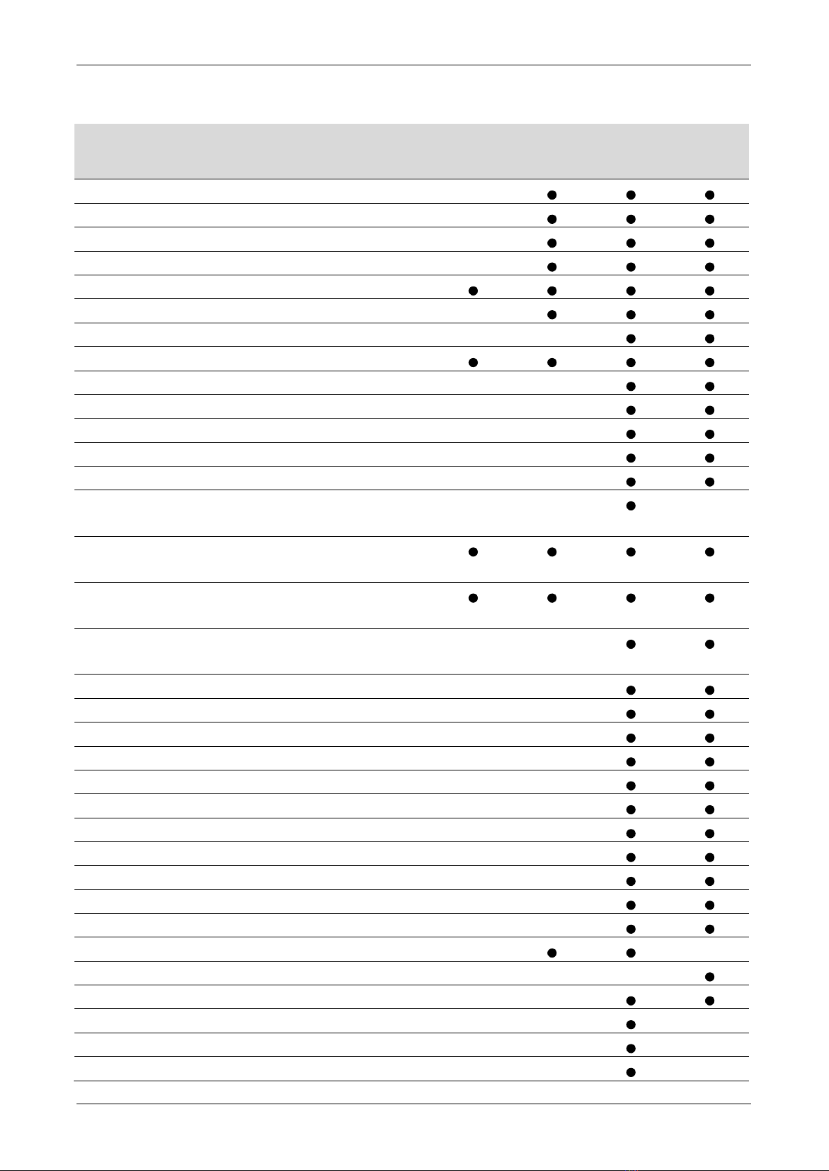
8.5 Trip Codes
Trip
Code
Description
CSX
CSX
i
EMX3
MV
1 Excess start time
2
Motor overload
3
Motor thermistor
4
Current imbalance
5
Frequency
6 Phase sequence
7
Instantaneous overcurrent
8
Power loss
9
Undercurrent
10
Heatsink (starter) overtemperature
11 Motor connection
12 Input A trip
13
FLC too high
14
Unsupported option (function not
available in inside delta)
15
Starter communication (between
device and soft starter)
16
Network communication (between
device and network)
17
Internal fault x (where x is the fault
code detailed in the table below)
201Ground fault
23
Parameter out of range
24
Input B trip
25
Bypass fail (bypass contactor)
26
L1 phase loss
27 L2 phase loss
28 L3 phase loss
29
L1-T1 shorted
30
L2-T2 shorted
31
L3-T3 shorted
32
Motor 2 overload
332Time-overcurrent (Bypass overload)
34 SCR overtemperature
35
Battery/clock
36
Thermistor circuit
37
RTD/PT100 A
38
1
RTD/PT100 B

USER MANUAL
20 Modbus TCP Interface (710-14812-00D)
Trip
Code
Description
CSX
CSX
i
EMX3
MV
39
1
RTD/PT100 C
40
1
RTD/PT100 D
41
1
RTD/PT100 E
421RTD/PT100 F
431RTD/PT100 G
45
RTD circuit fail
46
Analog input trip
1Available with EMX3 only if the appropriate option card is fitted.
2For EMX3, time-overcurrent protection is only available on internally bypassed
models.
Internal Fault X
The table below details the internal fault code associated with trip code 17.
Internal fault
Message displayed on the keypad
70 ~ 72 Current Read Err Lx
73
ATTENTION! Remove Mains Volts
74 ~ 76
Motor Connection Tx
77 ~ 79 Firing Fail Px
80 ~ 82
VZC Fail Px
83 Low Control Volts
84 ~ 98
Internal fault X
Contact your local supplier with the fault code (X).
Table of contents


