Removing and installing --> Rear Vehicle Level Sensor , removing and installing
After loosening, adapt control position again --> Control position, adapting again
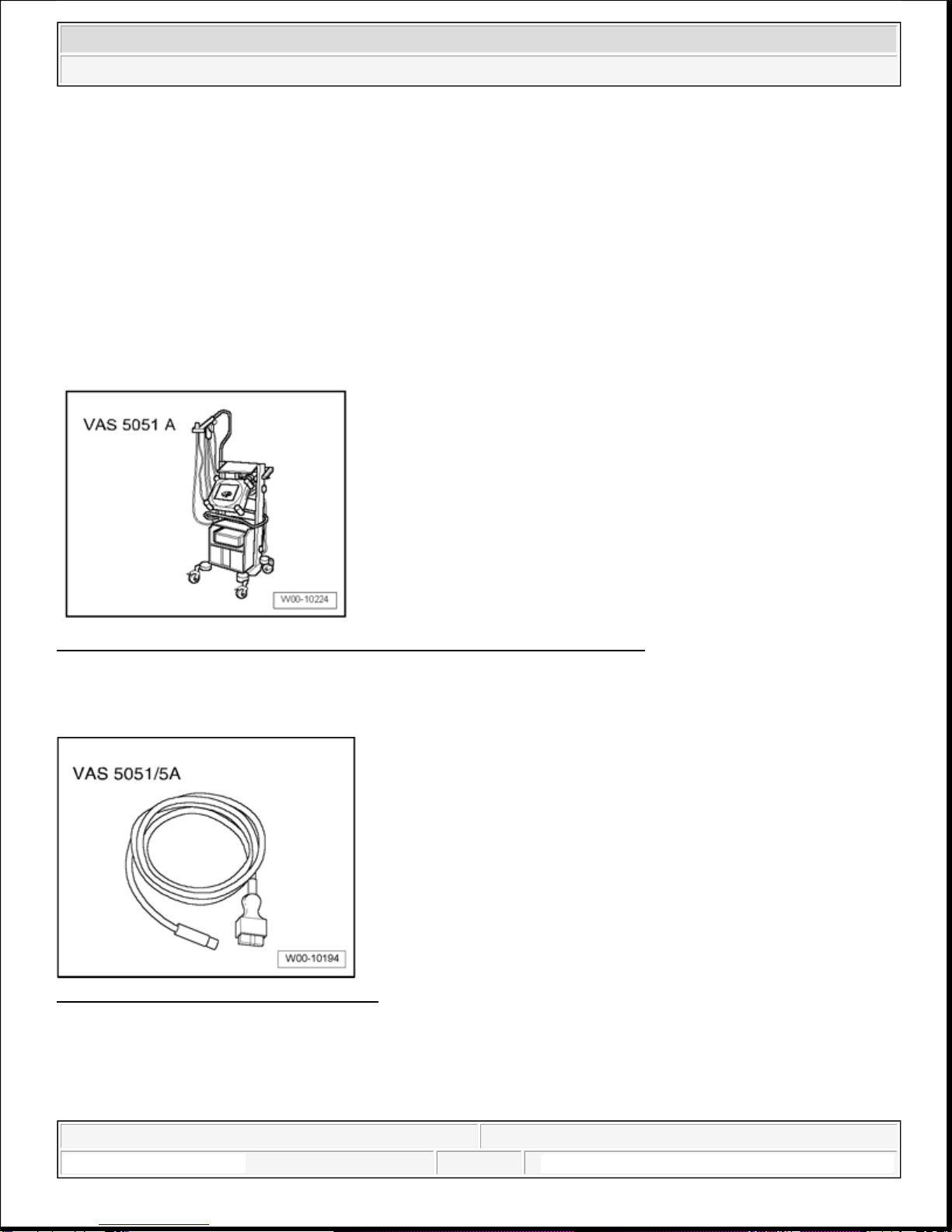
Can be checked in "Guided Fault Finding" using VAS 5051 A
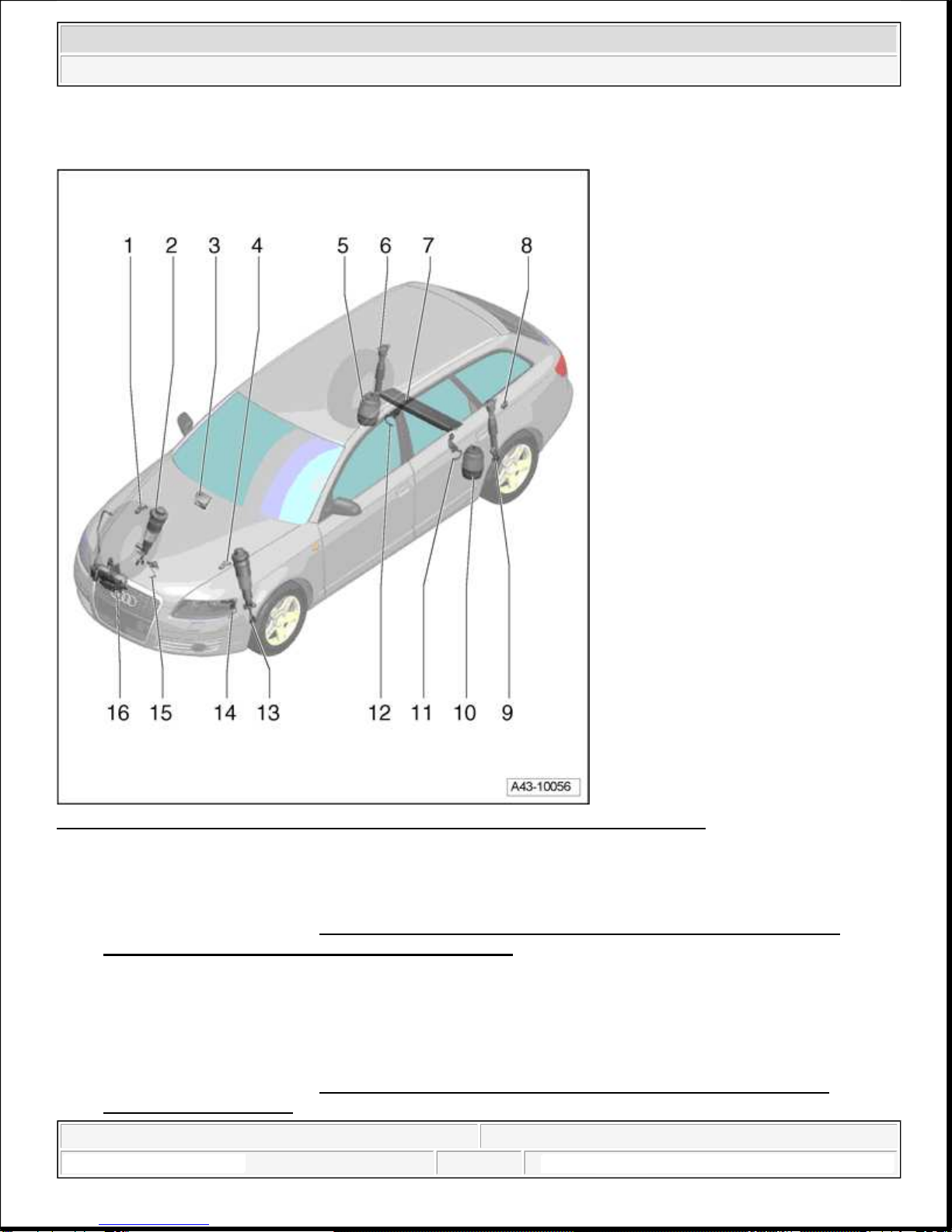
12 - Right Rear Level Control System Sensor G77
Removing and installing --> Rear Vehicle Level Sensor , removing and installing
After loosening, adapt control position again --> Control position, adapting again
Can be checked in "Guided Fault Finding" using VAS 5051 A
13 - Left front suspension strut (air spring suspension)
With Left Front Dampening Adjustment Valve N336
Removing and installing --> Suspension strut (air spring suspension) with mounting bracket,
removing and installing
14 - Left Front Level Control System Sensor G78
Removing and installing --> Front Vehicle Level Sensor , removing and installing
After loosening, adapt control position again --> Control position, adapting again
Can be checked in "Guided Fault Finding" using VAS 5051 A
15 - Right Front Level Control Sensor G289
Removing and installing --> Front Vehicle Level Sensor , removing and installing
After loosening, adapt control position again --> Control position, adapting again
Can be checked in "Guided Fault Finding" using VAS 5051 A
16 - Air supply unit with solenoid valve block
Removing and installing air supply unit --> Air supply unit, removing and installing
Removing and installing solenoid valve block --> Solenoid valve block, removing and installing
Front Vehicle Level Sensor , removing and installing
General Information
Vehicles with level control system and/or with gas-discharge headlights have an automatic vertical aim control
system as standard equipment --> 94 - LIGHTS, SWITCHES - EXTERIOR .
To function properly, the vehicle level control system and automatic vertical aim control system require
information about compression travel or rebound travel at front and rear axles.
For this, position of left/right control arm in relation to body is transferred via a coupling rod to Left Front
2008 Audi A6 Quattro
SUSPENSION Suspension, Wheels, Steering
FIXYOURCAR
1:42:00 AM Page 10