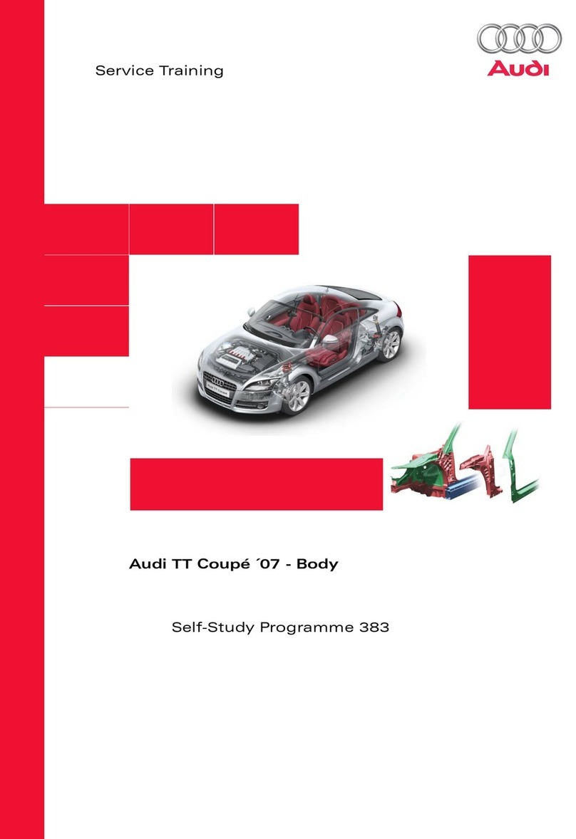
Audi TT 207 Operating instructions

Protected by copyright. Copying for private or commercial purposes, in part or in whole, is not
permitted unless authorised by AUDI AG. AUDI AG does not guarantee or accept any liability
with respect to the correctness of information in this document. Copyright by AUDI AG.
Repair Manual
Audi TT 2007 ➤
Body Exterior
Edition 11.2010
Service
Service Department. Technical Information

Protected by copyright. Copying for private or commercial purposes, in part or in whole, is not
permitted unless authorised by AUDI AG. AUDI AG does not guarantee or accept any liability
with respect to the correctness of information in this document. Copyright by AUDI AG.
List of Workshop Manual Repair GroupsList of Workshop Manual
Repair GroupsList of Workshop Manual Repair Groups
Repair Group
00 - General, Technical Data
50 - Body Front
55 - Hood, Lids
57 - Front Doors, Central Locking System
61 - Convertible Top
63 - Bumpers
64 - Glass, Window Regulators
66 - Exterior Equipment
Technical information should always be available to the foremen and mechanics, because their
careful and constant adherence to the instructions is essential to ensure vehicle road-worthiness and
safety. In addition, the normal basic safety precautions for working on motor vehicles must, as a
matter of course, be observed.
Service
All rights reserved.
No reproduction without prior agreement from publisher.
Copyright © 2011 Audi AG, Ingolstadt D3E8006F7B3

Protected by copyright. Copying for private or commercial purposes, in part or in whole, is not
permitted unless authorised by AUDI AG. AUDI AG does not guarantee or accept any liability
with respect to the correctness of information in this document. Copyright by AUDI AG.
Contents
00 - General, Technical Data . . . . . . . . . . . . . . . . . . . . . . . . . . . . . . . . . . . . . . . . . . . . 1
1 General Information . . . . . . . . . . . . . . . . . . . . . . . . . . . . . . . . . . . . . . . . . . . . . . . . . . . . . . 1
1.1 Lines, Routing and Securing . . . . . . . . . . . . . . . . . . . . . . . . . . . . . . . . . . . . . . . . . . . . . . . . 1
1.2 Contact Corrosion . . . . . . . . . . . . . . . . . . . . . . . . . . . . . . . . . . . . . . . . . . . . . . . . . . . . . . . . 1
1.3 Adhesive Tape Surfaces . . . . . . . . . . . . . . . . . . . . . . . . . . . . . . . . . . . . . . . . . . . . . . . . . . 1
50 - Body Front . . . . . . . . . . . . . . . . . . . . . . . . . . . . . . . . . . . . . . . . . . . . . . . . . . . . . . 2
1 Removal and Installation . . . . . . . . . . . . . . . . . . . . . . . . . . . . . . . . . . . . . . . . . . . . . . . . . . 2
1.1 Front Fenders . . . . . . . . . . . . . . . . . . . . . . . . . . . . . . . . . . . . . . . . . . . . . . . . . . . . . . . . . . . . 2
1.2 Engine Mount Brace . . . . . . . . . . . . . . . . . . . . . . . . . . . . . . . . . . . . . . . . . . . . . . . . . . . . . . 3
1.3 Lock Carrier with Attachments . . . . . . . . . . . . . . . . . . . . . . . . . . . . . . . . . . . . . . . . . . . . . . 4
1.4 Plenum Chamber Cover . . . . . . . . . . . . . . . . . . . . . . . . . . . . . . . . . . . . . . . . . . . . . . . . . . . . 5
1.5 Engine Mount Brace Reinforcement . . . . . . . . . . . . . . . . . . . . . . . . . . . . . . . . . . . . . . . . . . 6
1.6 Bumper Bracket . . . . . . . . . . . . . . . . . . . . . . . . . . . . . . . . . . . . . . . . . . . . . . . . . . . . . . . . . . 7
1.7 Noise Insulation Frame . . . . . . . . . . . . . . . . . . . . . . . . . . . . . . . . . . . . . . . . . . . . . . . . . . . . 8
1.8 Fender Brace . . . . . . . . . . . . . . . . . . . . . . . . . . . . . . . . . . . . . . . . . . . . . . . . . . . . . . . . . . . . 8
1.9 Fender End Plate . . . . . . . . . . . . . . . . . . . . . . . . . . . . . . . . . . . . . . . . . . . . . . . . . . . . . . . . 9
55 - Hood, Lids . . . . . . . . . . . . . . . . . . . . . . . . . . . . . . . . . . . . . . . . . . . . . . . . . . . . . . 10
1 Description and Operation . . . . . . . . . . . . . . . . . . . . . . . . . . . . . . . . . . . . . . . . . . . . . . . . . . 10
1.1 Hood - TT . . . . . . . . . . . . . . . . . . . . . . . . . . . . . . . . . . . . . . . . . . . . . . . . . . . . . . . . . . . . . . 10
1.2 Hood - TT RS . . . . . . . . . . . . . . . . . . . . . . . . . . . . . . . . . . . . . . . . . . . . . . . . . . . . . . . . . . . . 12
1.3 Rear Lid - Coupe . . . . . . . . . . . . . . . . . . . . . . . . . . . . . . . . . . . . . . . . . . . . . . . . . . . . . . . . 18
1.4 Rear Lid - Roadster . . . . . . . . . . . . . . . . . . . . . . . . . . . . . . . . . . . . . . . . . . . . . . . . . . . . . . 20
2 Removal and Installation . . . . . . . . . . . . . . . . . . . . . . . . . . . . . . . . . . . . . . . . . . . . . . . . . . 26
2.1 Hood - TT . . . . . . . . . . . . . . . . . . . . . . . . . . . . . . . . . . . . . . . . . . . . . . . . . . . . . . . . . . . . . . 26
2.2 Hood - TT RS . . . . . . . . . . . . . . . . . . . . . . . . . . . . . . . . . . . . . . . . . . . . . . . . . . . . . . . . . . . . 38
2.3 Rear Lid - Coupe . . . . . . . . . . . . . . . . . . . . . . . . . . . . . . . . . . . . . . . . . . . . . . . . . . . . . . . . 50
2.4 Rear Lid Roadster . . . . . . . . . . . . . . . . . . . . . . . . . . . . . . . . . . . . . . . . . . . . . . . . . . . . . . . . 59
2.5 Fuel Filler Door . . . . . . . . . . . . . . . . . . . . . . . . . . . . . . . . . . . . . . . . . . . . . . . . . . . . . . . . . . 67
3 Special Tools . . . . . . . . . . . . . . . . . . . . . . . . . . . . . . . . . . . . . . . . . . . . . . . . . . . . . . . . . . . . 72
57 - Front Doors, Central Locking System . . . . . . . . . . . . . . . . . . . . . . . . . . . . . . . . . . 73
1 Description and Operation . . . . . . . . . . . . . . . . . . . . . . . . . . . . . . . . . . . . . . . . . . . . . . . . . . 73
1.1 Front Door . . . . . . . . . . . . . . . . . . . . . . . . . . . . . . . . . . . . . . . . . . . . . . . . . . . . . . . . . . . . . . 73
1.2 Central Locking . . . . . . . . . . . . . . . . . . . . . . . . . . . . . . . . . . . . . . . . . . . . . . . . . . . . . . . . . . 79
2 Removal and Installation . . . . . . . . . . . . . . . . . . . . . . . . . . . . . . . . . . . . . . . . . . . . . . . . . . 80
2.1 Front Door . . . . . . . . . . . . . . . . . . . . . . . . . . . . . . . . . . . . . . . . . . . . . . . . . . . . . . . . . . . . . . 80
2.2 Door Components . . . . . . . . . . . . . . . . . . . . . . . . . . . . . . . . . . . . . . . . . . . . . . . . . . . . . . . . 87
2.3 Central Locking . . . . . . . . . . . . . . . . . . . . . . . . . . . . . . . . . . . . . . . . . . . . . . . . . . . . . . . . . . 98
3 Special Tools . . . . . . . . . . . . . . . . . . . . . . . . . . . . . . . . . . . . . . . . . . . . . . . . . . . . . . . . . . . . 104
61 - Convertible Top . . . . . . . . . . . . . . . . . . . . . . . . . . . . . . . . . . . . . . . . . . . . . . . . . . 106
1 Description and Operation . . . . . . . . . . . . . . . . . . . . . . . . . . . . . . . . . . . . . . . . . . . . . . . . . . 106
1.1 Convertible Top . . . . . . . . . . . . . . . . . . . . . . . . . . . . . . . . . . . . . . . . . . . . . . . . . . . . . . . . . . 106
1.2 Convertible Top Hydraulic System . . . . . . . . . . . . . . . . . . . . . . . . . . . . . . . . . . . . . . . . . . . . 113
2 Removal and Installation . . . . . . . . . . . . . . . . . . . . . . . . . . . . . . . . . . . . . . . . . . . . . . . . . . 119
2.1 Convertible Top . . . . . . . . . . . . . . . . . . . . . . . . . . . . . . . . . . . . . . . . . . . . . . . . . . . . . . . . . . 119
2.2 Convertible Top Hydraulic System . . . . . . . . . . . . . . . . . . . . . . . . . . . . . . . . . . . . . . . . . . . . 148
3 Special Tools . . . . . . . . . . . . . . . . . . . . . . . . . . . . . . . . . . . . . . . . . . . . . . . . . . . . . . . . . . . . 154
63 - Bumpers . . . . . . . . . . . . . . . . . . . . . . . . . . . . . . . . . . . . . . . . . . . . . . . . . . . . . . . . 155
Audi TT 2007 ➤
Body Exterior - Edition 11.2010
Contents i

Protected by copyright. Copying for private or commercial purposes, in part or in whole, is not
permitted unless authorised by AUDI AG. AUDI AG does not guarantee or accept any liability
with respect to the correctness of information in this document. Copyright by AUDI AG.
1 Description and Operation . . . . . . . . . . . . . . . . . . . . . . . . . . . . . . . . . . . . . . . . . . . . . . . . . . 155
1.1 Front Bumper - Audi TT . . . . . . . . . . . . . . . . . . . . . . . . . . . . . . . . . . . . . . . . . . . . . . . . . . . . 155
1.2 Front Bumper - Audi TT RS . . . . . . . . . . . . . . . . . . . . . . . . . . . . . . . . . . . . . . . . . . . . . . . . 156
1.3 Rear Bumper - Audi TT . . . . . . . . . . . . . . . . . . . . . . . . . . . . . . . . . . . . . . . . . . . . . . . . . . . . 159
1.4 Rear Bumper - Audi TT RS . . . . . . . . . . . . . . . . . . . . . . . . . . . . . . . . . . . . . . . . . . . . . . . . 160
2 Removal and Installation . . . . . . . . . . . . . . . . . . . . . . . . . . . . . . . . . . . . . . . . . . . . . . . . . . 164
2.1 Front Bumper - Audi TT . . . . . . . . . . . . . . . . . . . . . . . . . . . . . . . . . . . . . . . . . . . . . . . . . . . . 164
2.2 Front Bumper - Audi TT RS . . . . . . . . . . . . . . . . . . . . . . . . . . . . . . . . . . . . . . . . . . . . . . . . 170
2.3 Rear Bumper - Audi TT . . . . . . . . . . . . . . . . . . . . . . . . . . . . . . . . . . . . . . . . . . . . . . . . . . . . 174
2.4 Rear Bumper - Audi TT RS . . . . . . . . . . . . . . . . . . . . . . . . . . . . . . . . . . . . . . . . . . . . . . . . 182
3 Special Tools . . . . . . . . . . . . . . . . . . . . . . . . . . . . . . . . . . . . . . . . . . . . . . . . . . . . . . . . . . . . 189
64 - Glass, Window Regulators . . . . . . . . . . . . . . . . . . . . . . . . . . . . . . . . . . . . . . . . . . 190
1 Description and Operation . . . . . . . . . . . . . . . . . . . . . . . . . . . . . . . . . . . . . . . . . . . . . . . . . . 190
1.1 Flush-Bonded Windows . . . . . . . . . . . . . . . . . . . . . . . . . . . . . . . . . . . . . . . . . . . . . . . . . . . . 190
1.2 Bolted Windows . . . . . . . . . . . . . . . . . . . . . . . . . . . . . . . . . . . . . . . . . . . . . . . . . . . . . . . . . . 193
2 Removal and Installation . . . . . . . . . . . . . . . . . . . . . . . . . . . . . . . . . . . . . . . . . . . . . . . . . . 196
2.1 Flush-Bonded Windows . . . . . . . . . . . . . . . . . . . . . . . . . . . . . . . . . . . . . . . . . . . . . . . . . . . . 196
2.2 Bolted Windows . . . . . . . . . . . . . . . . . . . . . . . . . . . . . . . . . . . . . . . . . . . . . . . . . . . . . . . . . . 212
3 Special Tools . . . . . . . . . . . . . . . . . . . . . . . . . . . . . . . . . . . . . . . . . . . . . . . . . . . . . . . . . . . . 216
66 - Exterior Equipment . . . . . . . . . . . . . . . . . . . . . . . . . . . . . . . . . . . . . . . . . . . . . . . . 219
1 Description and Operation . . . . . . . . . . . . . . . . . . . . . . . . . . . . . . . . . . . . . . . . . . . . . . . . . . 219
1.1 Exterior Rearview Mirror . . . . . . . . . . . . . . . . . . . . . . . . . . . . . . . . . . . . . . . . . . . . . . . . . . . . 219
1.2 Radiator Grille - TT RS . . . . . . . . . . . . . . . . . . . . . . . . . . . . . . . . . . . . . . . . . . . . . . . . . . . . 220
2 Specifications . . . . . . . . . . . . . . . . . . . . . . . . . . . . . . . . . . . . . . . . . . . . . . . . . . . . . . . . . . . . 221
2.1 Lettering . . . . . . . . . . . . . . . . . . . . . . . . . . . . . . . . . . . . . . . . . . . . . . . . . . . . . . . . . . . . . . . . 221
2.2 Spoiler - TT . . . . . . . . . . . . . . . . . . . . . . . . . . . . . . . . . . . . . . . . . . . . . . . . . . . . . . . . . . . . . . 223
2.3 Spoiler - TT RS . . . . . . . . . . . . . . . . . . . . . . . . . . . . . . . . . . . . . . . . . . . . . . . . . . . . . . . . . . 224
3 Removal and Installation . . . . . . . . . . . . . . . . . . . . . . . . . . . . . . . . . . . . . . . . . . . . . . . . . . 227
3.1 Trim Moldings and Trim . . . . . . . . . . . . . . . . . . . . . . . . . . . . . . . . . . . . . . . . . . . . . . . . . . . . 227
3.2 Exterior Rearview Mirror . . . . . . . . . . . . . . . . . . . . . . . . . . . . . . . . . . . . . . . . . . . . . . . . . . . . 231
3.3 Radiator Grille - Audi TT . . . . . . . . . . . . . . . . . . . . . . . . . . . . . . . . . . . . . . . . . . . . . . . . . . . . 235
3.4 Radiator Grille - TT RS . . . . . . . . . . . . . . . . . . . . . . . . . . . . . . . . . . . . . . . . . . . . . . . . . . . . 236
3.5 Spoiler - TT . . . . . . . . . . . . . . . . . . . . . . . . . . . . . . . . . . . . . . . . . . . . . . . . . . . . . . . . . . . . . . 237
3.6 Spoiler - TT RS . . . . . . . . . . . . . . . . . . . . . . . . . . . . . . . . . . . . . . . . . . . . . . . . . . . . . . . . . . 240
3.7 Underbody Trim Panels and Heat Shields . . . . . . . . . . . . . . . . . . . . . . . . . . . . . . . . . . . . . . 248
3.8 Wheel Housing Liners . . . . . . . . . . . . . . . . . . . . . . . . . . . . . . . . . . . . . . . . . . . . . . . . . . . . 255
4 Special Tools . . . . . . . . . . . . . . . . . . . . . . . . . . . . . . . . . . . . . . . . . . . . . . . . . . . . . . . . . . . . 257
Audi TT 2007 ➤
Body Exterior - Edition 11.2010
ii Contents

Protected by copyright. Copying for private or commercial purposes, in part or in whole, is not
permitted unless authorised by AUDI AG. AUDI AG does not guarantee or accept any liability
with respect to the correctness of information in this document. Copyright by AUDI AG.
00 – General, Technical Data
1 General Information
⇒ “1.1 Lines, Routing and Securing“, page 1
⇒ “1.2 Contact Corrosion“, page 1
⇒ “1.3 Adhesive Tape Surfaces“, page 1
1.1 Lines, Routing and Securing
When removing and installing hydraulic and pneumatic lines or
electrical wires, make a sketch or take a photo to remember the
original installation locations.
1.2 Contact Corrosion
Contact corrosion can occur if incorrect connecting elements
(bolts, nuts, washers, etc.) are used.
For this reason, only connecting elements with a special surface
coating are installed.
Furthermore, all rubber or plastic and adhesive are made of non-
conductive materials.
If you have doubts about the reusability of parts, use new parts
from the replacement parts catalog.
Note
♦
It is recommended to use only original replacement parts as
they have been tested and are compatible with aluminum.
♦
It is recommended to use Audi accessories.
♦
Warranty does not cover contact corrosion damage.
1.3 Adhesive Tape Surfaces
♦ The vehicle must be at room temperature before the installa‐
tion of self-adhesive cover, door seal molding, etc. when using
adhesive tape.
♦ The adhesive surfaces on the body must be free of dirt and
grease.
♦ Clean the adhesive surfaces using cleaning solution -D 009
401 04- .
♦ Warm the adhesive areas to approximately 104 ºF (40 ℃) us‐
ing a hot air gun.
♦ After installing the covers with adhesive tape, use a roller and
press the adhesive tape one more time to make sure it is on
securely.
♦ After that, pull on the adhesive tape by hand just to make sure
it is on.
Audi TT 2007 ➤
Body Exterior - Edition 11.2010
1. General Information 1

Protected by copyright. Copying for private or commercial purposes, in part or in whole, is not
permitted unless authorised by AUDI AG. AUDI AG does not guarantee or accept any liability
with respect to the correctness of information in this document. Copyright by AUDI AG.
50 – Body Front
1 Removal and Installation
⇒ “1.1 Front Fenders“, page 2
⇒ “1.2 Engine Mount Brace“, page 3
⇒ “1.3 Lock Carrier with Attachments“, page 4
⇒ “1.4 Plenum Chamber Cover“, page 5
⇒ “1.5 Engine Mount Brace Reinforcement“, page 6
⇒ “1.6 Bumper Bracket“, page 7
⇒ “1.7 Noise Insulation Frame“, page 8
⇒ “1.8 Fender Brace“, page 8
⇒ “1.9 Fender End Plate“, page 9
1.1 Front Fenders
1 - Bolt
❑ 11 Nm
2 - Bracket
3 - Fender
❑ Removing
❑ Loosen sill panel cover
in fender area.
❑ Headlamp removed, re‐
fer to ⇒ Electrical Equip‐
ment; Rep. Gr. 94 ;
Removal and Installa‐
tion
– Remove the front bump‐
er:
❑ Audi TT:
⇒ “2.1.2 Front Bumper“,
page 165 ,
❑ Audi TT RS:
⇒ “2.2.1 Front Bumper“,
page 170
– Remove wheel housing
liner. Refer to
⇒ “3.8.1 Front Wheel
Housing Liner“,
page 255 .
– End plate, removing, re‐
fer to ⇒ page 9
– Remove bolts and re‐
move fender.
❑ Installation: in reverse
order.
4 - Brace
Audi TT 2007 ➤
Body Exterior - Edition 11.2010
2 Rep. Gr.50 - Body Front

Protected by copyright. Copying for private or commercial purposes, in part or in whole, is not
permitted unless authorised by AUDI AG. AUDI AG does not guarantee or accept any liability
with respect to the correctness of information in this document. Copyright by AUDI AG.
1.2 Engine Mount Brace
Roadster
1 - Engine mount
Removal, refer to ⇒ Engine
Mechanical, Fuel Injection and
Ignition; Rep. Gr. 10 ; Specifi‐
cations
2 - Engine mount brace
❑ Remove nut -5- and
bolts -3-.
3 - Bolt
❑ 23 Nm
4 - Internally threaded pop rivet
5 - Nut
❑ 10 Nm
6 - Special bolt
❑ Do not remove for brace
removal.
❑ Torque, refer to ⇒ En‐
gine Mechanical, Fuel
Injection and Ignition;
Rep. Gr. 10 ; Specifica‐
tions
Audi TT 2007 ➤
Body Exterior - Edition 11.2010
1. Removal and Installation 3

Protected by copyright. Copying for private or commercial purposes, in part or in whole, is not
permitted unless authorised by AUDI AG. AUDI AG does not guarantee or accept any liability
with respect to the correctness of information in this document. Copyright by AUDI AG.
1.3 Lock Carrier with Attachments
1 - Lock washer
❑ Secures the impact
member and must not
be loosened to remove
the lock carrier.
2 - Bolt
❑ 30 Nm
3 - Side impact bar
❑ Must not be removed
from bumper bracket
with removing lock car‐
rier.
4 - Bolt
❑ 6 Nm
5 - Lock carrier
Note
❑ Removing
– Remove the front bump‐
er:
❑ Audi TT
⇒ “2.1.2 Front Bumper“,
page 165
❑ Audi TT RS
⇒ “2.2.1 Front Bumper“,
page 170
– Remove headlight. Re‐
fer to ⇒ Electrical Equip‐
ment; Rep. Gr. 94 ;
Removal and Installa‐
tion
– Disconnect the control
cable for the front lid lock from the coupling:, .
❑ Audi TT: ⇒ “2.1.6 Front Hood Lock Release Cable“, page 31
❑ Audi TT RS: ⇒ “2.2.13 Hood Lock Control Cable Mount“, page 47
– Remove bolts -2- on longitudinal member.
Note
– Remove bolts -6- on fender and bolts -4-.
– Remove lock carrier toward front.
❑ Installation: in reverse order.
6 - Bolt
❑ 23 Nm
7 - Frame
❑ Removing, refer to ⇒ page 8
Audi TT 2007 ➤
Body Exterior - Edition 11.2010
4 Rep. Gr.50 - Body Front

Protected by copyright. Copying for private or commercial purposes, in part or in whole, is not
permitted unless authorised by AUDI AG. AUDI AG does not guarantee or accept any liability
with respect to the correctness of information in this document. Copyright by AUDI AG.
1.4 Plenum Chamber Cover
1 - Hood seal
❑ When installed correct‐
ly, seal must lie over ple‐
num chamber cover as
shown in the illustration.
2 - Plenum chamber cover
❑ Wiper arms removed.
Note
❑ Lid seal removed.
❑ Remove trim panel up‐
ward diagonally from
edge strip beginning at
window edge.
❑ Vehicles with bolts
⇒ page 6
Caution
Risk of window breaking
during installation
Do not hit the trim when
installing it.
Carefully press in trim
sideways, beginning in
edge strip.
3 - Molding
❑ For easier removal/in‐
stallation of plenum
chamber cover, spray
molding with soapy sol‐
ution.
❑ No replacement part
4 - Windshield
5 - Plenum chamber
6 - Bulkhead trim
Audi TT 2007 ➤
Body Exterior - Edition 11.2010
1. Removal and Installation 5

Protected by copyright. Copying for private or commercial purposes, in part or in whole, is not
permitted unless authorised by AUDI AG. AUDI AG does not guarantee or accept any liability
with respect to the correctness of information in this document. Copyright by AUDI AG.
Plenum Chamber Cover with Screws
– Remove the bolts -3- and -4-.
– Remove rubber seal -1-.
– Pull plenum chamber cover -2- vertically up from the window
edge starting carefully with the windshield catches -arrows-.
1.5 Engine Mount Brace Reinforcement
1 - Engine mount brace
❑ If brace must be re‐
moved from bracket, re‐
move bolts -2-.
WARNING
When installing, rein‐
forcement -3- must be
slid into brace -1-.
2 - Bolt
❑ 23 Nm
❑ When tightening to tor‐
que, counterhold at nut
-5- with open end
wrench.
3 - Brace reinforcement
4 - Bracket
5 - Nut
Audi TT 2007 ➤
Body Exterior - Edition 11.2010
6 Rep. Gr.50 - Body Front

Protected by copyright. Copying for private or commercial purposes, in part or in whole, is not
permitted unless authorised by AUDI AG. AUDI AG does not guarantee or accept any liability
with respect to the correctness of information in this document. Copyright by AUDI AG.
1.6 Bumper Bracket
Removing
1 - Right bumper bracket
❑ Remove bolts -2- from
lock carrier-4-
2 - Bolt
❑ 5 Nm
3 - Left bumper bracket
❑ Remove bolts -2- from
lock carrier-4-
4 - Lock Carrier
Audi TT 2007 ➤
Body Exterior - Edition 11.2010
1. Removal and Installation 7

Protected by copyright. Copying for private or commercial purposes, in part or in whole, is not
permitted unless authorised by AUDI AG. AUDI AG does not guarantee or accept any liability
with respect to the correctness of information in this document. Copyright by AUDI AG.
1.7 Noise Insulation Frame
Removing
1 - Frame
❑ Noise insulation re‐
moved.
❑ Remove bolts -2- and
-3- and remove frame.
2 - Bolt
❑ 23 Nm
3 - Bolt
❑ 23 Nm
4 - Internally threaded pop rivet
5 - Longitudinal member
1.8 Fender Brace
– Fender removed.
– To remove, only loosen bolts -2- and slide brace forward out
of elongated holes.
♦ Bolts -2- 23 Nm
Audi TT 2007 ➤
Body Exterior - Edition 11.2010
8 Rep. Gr.50 - Body Front

Protected by copyright. Copying for private or commercial purposes, in part or in whole, is not
permitted unless authorised by AUDI AG. AUDI AG does not guarantee or accept any liability
with respect to the correctness of information in this document. Copyright by AUDI AG.
1.9 Fender End Plate
Removing
1 - End plate
– Remove front wheel.
– Remove wheel housing
liner. Refer to
⇒ “3.8.1 Front Wheel
Housing Liner“,
page 255 .
❑ Fluid reservoir, loosen‐
ing
– Remove plugs -3- and
slide end plate -1- out
downward.
❑
2 - Plugs
3 - Screws
❑ 11 Nm
Audi TT 2007 ➤
Body Exterior - Edition 11.2010
1. Removal and Installation 9

Protected by copyright. Copying for private or commercial purposes, in part or in whole, is not
permitted unless authorised by AUDI AG. AUDI AG does not guarantee or accept any liability
with respect to the correctness of information in this document. Copyright by AUDI AG.
55 – Hood, Lids
1 Description and Operation
⇒ “1.1 Hood - TT“, page 10
⇒ “1.2 Hood - TT RS“, page 12
⇒ “1.3 Rear Lid - Coupe“, page 18
⇒ “1.4 Rear Lid - Roadster“, page 20
1.1 Hood - TT
⇒ “1.1.1 Hood, Adjusting“, page 10
⇒ “1.1.2 Hood Hinge, Adjusting“, page 11
1.1.1 Hood, Adjusting
Special tools and workshop equipment required
♦ Adjusting Gauge -3371-
Gap Dimensions for Hood
• In -A- area = 3.5 mm +/- 0.5 mm.
• In -B- area = 4.5 mm +/- 0.5 mm
• In -C- area = 4.5 mm +/- 0.5 mm
• In -D- area = 4.0 mm to 2.5 mm (in transition area)
• In -E- area = 3.5 mm +/- 0.5 mm
• In -F- area = 3.5 mm +/- 0.5 mm
Buffer Stop for Height Adjustment
• Adjusting buffer -1- must lightly contact the lock carrier when
the lid is closed.
• Rubber buffers -2- act as a strike guard and should not make
contact with the lid closed.
Note
The adjusting buffers are used to adjust the height of the lid.
Audi TT 2007 ➤
Body Exterior - Edition 11.2010
10 Rep. Gr.55 - Hood, Lids

Protected by copyright. Copying for private or commercial purposes, in part or in whole, is not
permitted unless authorised by AUDI AG. AUDI AG does not guarantee or accept any liability
with respect to the correctness of information in this document. Copyright by AUDI AG.
Hood Projection
– For correct adjustment, lid -1- must project in the headlamp
area -2-.
• Dimension -a-= 3.5 mm +/- 0.5 mm
• Projection dimension -b- = 3 mm +/- 0.5 mm
1.1.2 Hood Hinge, Adjusting
♦ When changing the hinge, ensure that -a- = 12.5 mm and ad‐
just if necessary.
Audi TT 2007 ➤
Body Exterior - Edition 11.2010
1. Description and Operation 11

Protected by copyright. Copying for private or commercial purposes, in part or in whole, is not
permitted unless authorised by AUDI AG. AUDI AG does not guarantee or accept any liability
with respect to the correctness of information in this document. Copyright by AUDI AG.
1.2 Hood - TT RS
⇒ “1.2.1 Hood Assembly Overview“, page 12
⇒ “1.2.2 Hood Gap Dimensions“, page 13
⇒ “1.2.3 Hood, Adjusting“, page 14
⇒ “1.2.4 Hood Locks Assembly Overview“, page 16
⇒ “1.2.5 Hood Control Cable, Control Cable Operating Lever As‐
sembly overview“, page 17
⇒ “1.2.6 Hood Lock Cables, Adjusting“, page 18
1.2.1 Hood Assembly Overview
1 - Anti-rotation protection
❑ For the striker pin
❑ Removing and Instal‐
ling, refer to
⇒ “2.2.4 Left and Right
Striker Pins“, page 40
2 - Bolt
❑ 2 Nm
3 - Hood catch
❑ Removing and Instal‐
ling, refer to
⇒ “2.2.4 Left and Right
Striker Pins“, page 40
❑ Adjusting, refer to
⇒ “1.2.3 Hood, Adjust‐
ing“, page 14
4 - Hood
❑ Removing and Instal‐
ling, refer to
⇒ “2.2.1 Hood“,
page 38
5 - Nuts
❑ 9 Nm
6 - Striker pin with catch
❑ Removing and Instal‐
ling, refer to
⇒ “2.2.3 Striker Pin with
Catch“, page 39
7 - Rubber stop
8 - Adjusting buffer
❑ Adjusting, refer to
⇒ “1.2.3 Hood, Adjust‐
ing“, page 14
9 - Impact guard
❑ Removing and Installing, refer to ⇒ “2.2.5 Impact Guard“, page 40
10 - Hood hinge
❑ Removing and Installing, refer to ⇒ “2.2.2 Hood Hinge“, page 39
11 - Bolt
❑ Pay attention to different lengths.
❑ 34 Nm
Audi TT 2007 ➤
Body Exterior - Edition 11.2010
12 Rep. Gr.55 - Hood, Lids

Protected by copyright. Copying for private or commercial purposes, in part or in whole, is not
permitted unless authorised by AUDI AG. AUDI AG does not guarantee or accept any liability
with respect to the correctness of information in this document. Copyright by AUDI AG.
12 - Gas strut
❑ Removing and Installing, refer to ⇒ “2.2.6 Gas-Filled Strut“, page 40
13 - Ball head pin
❑ 23 Nm
14 - Nut
❑ 34 Nm
1.2.2 Hood Gap Dimensions
Hood Gap Dimensions with Respect To Radiator Grille, Bumper,
Headlamp
A - Hood to bumper
• Gap dimension-a- = 4.5 +/-
0.5 mm
-1- hood
-2- bumper
❑ Adjusting, refer to
⇒ “1.2.3 Hood, Adjust‐
ing“, page 14
B - Hood to radiator grille side
• Gap dimension -b- from top
to bottom = 4.0 to 2.5 +/- 0.5
mm
-1- hood
-3- Radiator grille
❑ Adjusting, refer to
⇒ “1.2.3 Hood, Adjust‐
ing“, page 14
C - Hood to radiator grille
• Gap dimension -c- = 4.4 +/-
0.5 mm
• Projection -d- = 1.5 +/- 0.5
mm
-1- hood
-3- Radiator grille
❑ Adjusting, refer to
⇒ “1.2.3 Hood, Adjust‐
ing“, page 14
D - Hood to headlamp
• Gap dimension -e- from top to bottom = 3.0 to 1.6 +/- 0.5 mm
• Projection -f- = 3.0 +/- 0.5 mm
Gap Dimensions of Hood to Fender, Front Door
Audi TT 2007 ➤
Body Exterior - Edition 11.2010
1. Description and Operation 13

Protected by copyright. Copying for private or commercial purposes, in part or in whole, is not
permitted unless authorised by AUDI AG. AUDI AG does not guarantee or accept any liability
with respect to the correctness of information in this document. Copyright by AUDI AG.
A - Hood to fender - headlamp
area
• Gap dimension-a- = 2.5 +/-
0.5 mm
-1- hood
-2- fender - front area
❑ Adjusting, refer to
⇒ “1.2.3 Hood, Adjust‐
ing“, page 14
B - Hood to front door
• Gap dimension -b- = 3.5 +/-
0.5 mm
• Projection -c- = 0.0 + 1.0
mm
-1- hood
-3- Front door
❑ Adjusting, refer to
⇒ “1.2.3 Hood, Adjust‐
ing“, page 14
C - Hood to fender - A-pillar
area
• Gap dimension -d- = 3.5 +/-
0.5 mm
• Projection -e- = 2.0 +/- 0.5
mm
-1- hood
-4- fender - rear area
❑ Adjusting, refer to
⇒ “1.2.3 Hood, Adjust‐
ing“, page 14
1.2.3 Hood, Adjusting
Special tools and workshop equipment required
♦ Adjustment gauge -3371-
Audi TT 2007 ➤
Body Exterior - Edition 11.2010
14 Rep. Gr.55 - Hood, Lids

Protected by copyright. Copying for private or commercial purposes, in part or in whole, is not
permitted unless authorised by AUDI AG. AUDI AG does not guarantee or accept any liability
with respect to the correctness of information in this document. Copyright by AUDI AG.
Procedure
• Gap dimensions, refer to
⇒ “1.2.2 Hood Gap Dimensions“, page 13 .
• For the correct tightening specifications, refer to
⇒ “1.2.1 Hood Assembly Overview“, page 12 .
Side and Length Adjustment at Hinge:
– Loosen the left and right nuts -A- on the hinge -2-.
– Adjust hood -1- in the lateral and longitudinal direction.
– Tighten the nuts.
Height Adjustment At Hinge:
– Loosen screws -B- and -C- on the hinge on the left and right.
– Adjust the height of hinge -2- in the area of screw -B-.
– Tighten the bolts.
Note
Check the lid hinge stop bolt height adjustment ⇒ page 39 .
Hood Lock Height Adjustment:
• For the correct tightening specifications; refer to
⇒ “1.2.4 Hood Locks Assembly Overview“, page 16 .
– Loosen the bolts -arrows-.
– Adjust the height of hood lock -1- in front lock carrier -2-.
• The striker pin with the hood catch must engage vertically in
the hood lock.
– Tighten the bolts.
Height Adjustment at Left and Right Hood Locks:
• For the correct tightening specifications; refer to
⇒ “1.2.1 Hood Assembly Overview“, page 12 .
– Remove the bolt -1- and the striker pin anti-twist mechanism
-2-.
– Install lid lock striker pin -3- in the hood as far as the stop and
then loosen it 3 turns.
• During the closing test, the lid must fall from the balance po‐
sition into the lid lock and engage completely.
– Change the striker pin height adjustment if necessary.
– Position the anti-twist mechanism -2- on the striker pin -3-.
– Secure the anti-twist mechanism with the screw.
Audi TT 2007 ➤
Body Exterior - Edition 11.2010
1. Description and Operation 15

Protected by copyright. Copying for private or commercial purposes, in part or in whole, is not
permitted unless authorised by AUDI AG. AUDI AG does not guarantee or accept any liability
with respect to the correctness of information in this document. Copyright by AUDI AG.
Adjust Stop Buffer:
• The inner stop buffers -1- act as a strike guard and should not
make contact with the hood closed.
– Adjust the height of the hood stop buffers by turning them
-arrows-.
1.2.4 Hood Locks Assembly Overview
1 - Nut
❑ 9 Nm
2 - Brace
3 - Bolt
❑ 11 Nm
4 - Bolt
❑ 11 Nm
5 - Anti-theft protection
6 - Right hood lock
❑ Removing and Instal‐
ling, refer to
⇒ “2.2.8 Left and Right
Hood Lock“, page 43
7 - Right mount for hood lock
8 - Bolt
❑ 3 Nm
9 - Left mount for hood lock
10 - Bolt
❑ 10 Nm
11 - Left hood lock
❑ Removing and Instal‐
ling, refer to
⇒ “2.2.8 Left and Right
Hood Lock“, page 43
12 - Front hood lock
❑ with the hood contact
switch -F266-
❑ Can be used to adjust
the hood height
⇒ “1.2.3 Hood, Adjust‐
ing“, page 14
❑ Removing and Installing, refer to ⇒ “2.2.7 Center Hood Lock“, page 42
13 - Bolt
❑ 11 Nm
Audi TT 2007 ➤
Body Exterior - Edition 11.2010
16 Rep. Gr.55 - Hood, Lids
Table of contents
Other Audi Automobile manuals

Audi
Audi A5 SPORTBACK Manual

Audi
Audi R8 2021 Instruction Manual

Audi
Audi A4 2017 Instruction Manual

Audi
Audi TT 2019 User manual

Audi
Audi R8 Spyder 2011 User manual

Audi
Audi TT Roadster User manual

Audi
Audi S4 Biturbo User manual

Audi
Audi S5 CABRIOLET User manual

Audi
Audi S4 Assembly instructions

Audi
Audi Q8 e-tron Sportback 2024 Instruction Manual

Audi
Audi Q7 User manual

Audi
Audi A8 2015 User manual

Audi
Audi A5 2021 Instruction Manual

Audi
Audi R8 - QUICK EFEENCE GUIDE User manual

Audi
Audi A8 User manual

Audi
Audi Audi S6 User manual

Audi
Audi TT Coupe 2014 User manual

Audi
Audi Q5 80A 2017 User manual

Audi
Audi A7 2021 Instruction Manual

Audi
Audi ST?SIS Instruction sheet