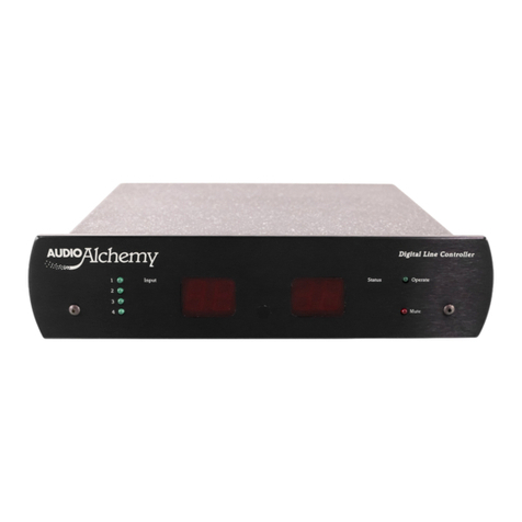
Audio Alchemy Line Input Selector Wiring diagram

Line Input Selector (LIS)
SUPPLEMENTARY INSTRUCTIONS to the DLC
Thank you for purchasing the new Audio Alchemy Line Input Selector (LIS). In order to get full
benefit of the system's available features, please read the following instructions before installation
and operation as there are several options you should be aware of prior to plugging everything in. A
little forethought now will save time reconnecting things later.
Initial configuration
In order for the DLC/LIS combination to work correctly, your DLC must recognize the LIS. This
requires that the micro-controller in the DLC be changed for the new one we've enclosed with the
LIS. To do this, remove power and disconnect all inputs from your DLC. Then install the enclosed
newly programmed Code Revision 2.6 micro-controller chip in your DLC by referring to the
enclosed drawing and following these directions:
1. Expose the internal circuit board by removing the 5 Phillips screws from the rear panel, which
secure the cover to the base assembly. Pull the cover back, away from the faceplate, to remove it.
2. Next, place the DLC with the faceplate towards you, and locate the original micro-controller U3
(it looks like the new one).
3. Grasp the ends ofU3 and pull up firmly to remove it from the socket. You may need to use a
small screwdriver to gently pry up on its ends.

4. Looking at the now-exposed socket, you will see a notch at the right end.
5. Carefully remove the new micro-controller chip from its static-protective bag and note that one
corner has a dot molded into it. Grasp the ends of the chip, trying to not touch any of its pins, and
remove it from the protective foam.
6. Align the end of the chip with the dot with the end of the socket that has the notch. Make
absolutely sure all the pins line up with all the socket openings before pressing down on the chip.
If the legs of the chip don't align with the socket you can bend the legs by pressing them against
the surface of a table while holding the ends of the chip. Now carefully, but firmly, press down
on the chip. Inspect your installation to be sure all pins are inserted.
7. The DLC's memory now has to be cleared so it can accept the new programming. Referring to
the drawing, locate the two jumper pins labeled J5. Push the enclosed shorting plug over these
pins.
8. Attach the DC power cord to the DLC (see the note about a possible spark in the beginning of the
next section) and then plug the AC cord into AC Mains. Count to 5, you will notice the display
indicating "CR 2.6", then "96 96". Remove the plug from the wall.
9. Remove the DC power cord and the shorting plug from J5.
10. Check all of your work described above before replacing the cover and screws. When replacing
the cover, you will need to be sure all of the protrusions from the jacks don't hang-up on the
inside of the cover. Push the cover on until you encounter the jacks. "Jiggle" each of the jacks to
assure that they pass through their corresponding hole, and then slide the cover on the rest of the
way.
11. Replace the 5 Phillips screws at the rear panel of the DLC.
Connections and Initial Operation
Return your DLC and its power supply to their original positions, and locate the remote power
supply for the LIS in a convenient location as well. For both units, do not plug it into AC Mains yet.
First, insert the power mini-plug firmly into the DC Power jack on the rear of each unit. Be sure the
mini-plug is inserted all the way in, so the body of the plug is touching the surface of the jack. In
doing so, you may see a small spark. Do not be alarmed! This is simply the residual power stored in
the power supply capacitors being discharged briefly by the ground terminal of the plug as it touches
the jack. No harm will occur.
Attach the enclosed 5-pin mini-DIN cable between DLC's output port and LIS's input port. They go
in with the flat surface of the connector facing up. Next, add a pair of short inter-connect cables,
from DLC's input 4 to LIS's "Line Outputs". Attach the "Tape Outputs" of the LIS to the analog input
of your tape/DAT/CD recorder. Read the "Operation" instructions, below, to determine which
additional sources you may want to attach to line inputs 1 through 4 of the LIS, as opposed to the
DLC. For example, one of our DAC's to improve your CD player, or a phono preamplifier such as
our VAC-in-the-BOX can be attached to one of these inputs to provide the use of a turntable.

Lastly, with your power amplifier(s) OFF, reattach your DLC to your amplifier. You can now
connect the DLC and LIS power supply's to AC Mains.
Programming Mode Changes
Several aspects of your DLC's programming mode have been changed with the new software. First,
to enter programming mode you no longer must power down the DLC. Simply place the RW-1 slide
switch in its center position and then sequentially depress and release the "Balance Left", "Balance
Right", "Volume Up" and "Volume Down" buttons while pointing the remote control at the DLC.
The display will then briefly show the word "PROG" and then flash "CLR?" asking if you wish to
clear the existing programming. Put the RW-1 slide switch in the forward position. If this is the first
time you have used the LIS you should press "MUTE" to accept and move to the next step. If you are
going through a reprogramming of your existing system and don't wish to change all of your existing
settings, say no to the clear question by pressing "SELECT" only. By the way, the key sequence
"Balance Left". "Balance Right", "Volume Up" and "Volume Down" to put the DLC into
programming mode should be done smoothly and quickly; try not to hold any key depressed for too
long. If it does not respond on your first attempt to enter this mode you can repeat the key sequence
until it docs. Please don't forget to go back to the slide switch forward position once you're in
programming mode. As in your original DLC, you will now be prompted to indicate your preference
to display volume in "dB" or the arbitrary "00-99" scale. As they alternately flash, press "MUTE"
when your choice is displayed, then "SELECT" to move on. All further programming procedures are
identical to DLC.
Operation
With the RW-1 slide switch in the forward position, your DLC/LIS combination now operates like a
seven input preamplifier. The "SELECT" switch will toggle the DLC from input 1, to 2, to 3, to 4.
The next press of the "SELECT" key activates input 1 of the LIS, then 2, to 3, to 4, then back to DLC
input 1. Any selected input is fed to your amplifier. Your recorder, however, gets something
different. Those sources plugged into the LIS inputs 1 through 4 are fed, buffered and not volume
adjusted, to the tape outputs. Thus, you will need to prioritize your inputs into those you feel you
may wish to record, and those you won't. Those you do should be plugged into the LIS, all others
into the DLC.
This arrangement works well if you always want to listen to the same source as you are taping. If you
don't, you can override the LIS from operating in tandem with the DLC by placing the RW-1 slide
switch in the center position again. Now the "SELECT" key will change only the LIS's inputs,
altering what you send to your Tape output to prevent any DLC keystroke from affecting the LIS,
press the "VOLUME UP" button while you have the switch in the middle position. To confirm this
change, the LIS "LINK" light will change from "LINE" to TAPE", indicating that you have
overridden the control linkage.

For example, let's say you want to listen to DLC input 2 while taping input 3 of the LIS. Move the
slide switch to the middle and "SELECT" LIS input 3 and press the "VOLUME UP" key to remove
the DLC/LIS link (illuminating the "TAPE" light), then place the RW-1 slide switch in the forward
position and "SELECT" DLC input 2. You can continue to operate Volume, Balance and Mute of the
DLC, none of which will affect the recording taking place through the LIS.
You can even "SELECT" a different DLC input to listen to, since the RW-1 now controls only the
DLC in the slide switch forward position. To "reconnect" the DLC and LIS, place the slide switch in
the middle position and press the "VOLUME DOWN" key, thus re-establishing the link between the
DLC and LIS; the "LINK" light will change back to "LINE".
Remember to place the RW-1 slide switch in the forward position when you wish to run the
combined DLC/LIS, and in the middle position to enter programming mode, or to operate LIS
separate from the DLC.
Your LIS is now ready to provide you with years of superior performance. Enjoy!
Audio Alchemy, Inc. Specifications and features subject to change without notice.
Lisinst.doc 4/10/95
Audio Alchemy, Inc.
31133 Via Colinas, Suite 111
Westlake Village, CA 91362 USA
(818) 707-8504 FAX 707-2610
This manual suits for next models
1
Table of contents
Other Audio Alchemy Recording Equipment manuals
