Satel INT-FI User manual

®
FIBER OPTIC INTERFACE
INT-FI
int-fi_en 04/12
The INT-FI interface allows for conversion and transmission of data by means of optical
fibers. It is dedicated to interacting with the communication buses of INTEGRA alarm control
panels or the RS-485 bus of ACCO access control system. The interface enables the
maximum distance between the devices to be increased up to 4 km.
This manual refers to the INT-FI interface with firmware version 1.02.
Note: Interfaces with firmware version 1.02 are not compatible with those with earlier
versions of firmware. Keep this in mind and, if necessary, update the firmware in
interfaces with older firmware versions.
1. Features
Conversion of signals sent through the keypad / expander buses of INTEGRA alarm
control panel and the RS-485 bus of ACCO access control system.
4 connectors for two fiber pairs.
Terminals for connecting electric signals from three communication buses of INTEGRA
control panels (one keypad bus and two expander buses) or one RS-485 bus of ACCO
access control system.
Operation in different configurations, depending on jumper settings.
Test mode to enable checking the correctness of data transmission.
LEDs indicating the selected configuration.
Up to 2 km transmission distance between two fiber optic interface units.
A possibility to extend the fiber optic distance up to 4 km in case of daisy chain topology
(see Fig. 6).
Support for popular multimode fibers.
Updateable firmware.
Immunity of data transmission through optical fibers to electromagnetic interference.
Galvanic isolation of devices ensured.

2 INT-FI SATEL
2. Description of Electronics Board
COM DTM CKM DT1 CK1 DT2 CK2 COM COM 12V
AB
RS
MS
RB
A
B
R
AB
HLHL
S
RX
(A)
TX
(A)
RX
(B)
TX
(B) 5
6
7
1
2
3
4
8
5/6
LH
H
LH
L
Fig. 1. View of the electronics board. L – jumper setting with the optical fiber length below
500 m; H – jumper setting with the optical fiber length over 500 m.
Explanations for Fig. 1:
1 - RS-232 port (TTL standard) for connecting the computer serial COM port. In order to
update the firmware, connect the socket to the computer, using the SATEL
manufactured cable (DB9FC/RJ-KPL set).
2 - interface configuration pins. By default, all jumpers are placed across the pins.
M S
RB
4
M S
RB
3
M S
RB
2
MS
RB
1
Fig. 2. Interface configuration method ( - pins shorted; - pins open):
1 – communication bus of INTEGRA control panel, the interface working on the control
panel side (Master);
2 – communication bus of INTEGRA control panel, the interface working on the keypads
/ expanders side (Slave);
3 – RS-485 bus;
4 – interface test mode.
3 - diagnostic LEDs, indicating the interface configuration:
1) for control panel communication buses or RS-485 bus:
A- jumper placed across the R/B pins,
B- jumpers placed across the R/B and M/S pins,
R- jumpers removed from the R/B and M/S pins.

SATEL INT-FI 3
2) for interface working in the test mode:
A– LED provides information on the interface A operating status:
– ON – data transmission is proceeding correctly,
– blinking – the received data are wrong,
– OFF – possible failure of the fiber cable connected to the RX socket.
B– LED provides information on the interface B operating status:
– ON – data transmission is proceeding correctly,
– blinking – the received data are wrong,
– OFF – possible failure of the fiber cable connected to the RX socket.
R– LED blinking regularly – interface running in the test mode.
4 - ST type connectors for multimode optical fibers with a diameter of 50/125 μm or
62,5/125 μm:
A- primary connectors (RX – receive; TX – transmit),
B- expansion connectors (RX – receive; TX – transmit), the role of which depends on
how the devices are connected – see Figures 5 and 6.
5 - pins enabling the transmitter diode current to be changed, depending on the length of
optical fibers connected to A connectors.
6 - pins enabling the transmitter diode current to be changed, depending on the length of
optical fibers connected to B connectors.
7 - LED indicating power supply presence and program operation.
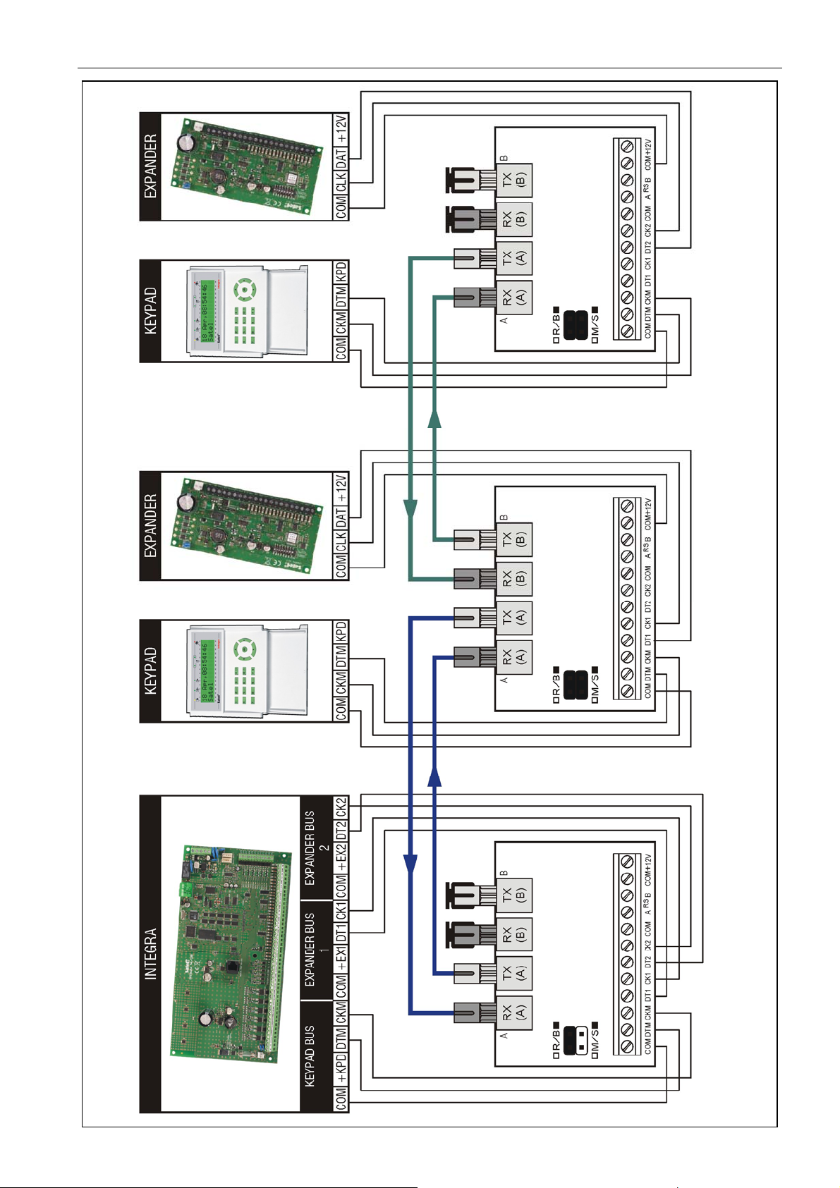
8 - terminals:
COM - common ground,
DTM - keypad bus data,
CKM - keypad bus clock,
DT1 - first expander bus data,
CK1 - first expander bus clock,
DT2 - second expander bus data,
CK2 - second expander bus clock,
A
RS
B - terminals for connecting RS-485 bus,
+12V - power supply input.
3. Installation
All electrical connections may only be made with disconnected power supply.
The INT-FI interface unit should be installed indoors, in spaces with normal air humidity. The
place where the unit is installed should be selected so as to ensure protection from
unauthorized access.
Connection to the INTEGRA control panel communication buses and to the source of
electrical power is to be made with a typical straight unscreened cable, as used in the
security alarm systems (using the twisted pair type of cable, e.g. UTP, STP, FTP is not
recommended). Connection to the RS-485 bus is to be made with the UTP type cable
(unscreened twisted pair). The length of optical fiber cable connecting two INT-FI interface
units can be up to 2 km.
Notes:
Configuration must be selected by placing jumpers across the R/B and M/S pins before
the power is turned on.

4 INT-FI SATEL
The distance between the INT-FI unit configured as Master and the control panel or
between the keypad / expander and the INT-FI unit configured as Slave can be up to
100 m.
Do not remove dust protection cap from the unused ST type connectors.
Fig. 3. An example of interaction between two INT-FI units and communication buses of
INTEGRA control panel. The unit on the control panel side is configured as Master (M/S
jumper removed), and the unit on the keypad / expander side is configured as Slave (M/S
jumper set). The unit working on the control panel side can be power supplied from the
control panel main board. The other unit can be supplied locally, from an independent power
source (additional power supply unit, expander with power supply). The unit working in Slave
configuration can accept a larger number of connected keypads and expanders than shown
in the illustration above.

SATEL INT-FI 5
Fig. 4. An example of interaction between two INT-FI units and RS-485 bus of ACCO access
control system. The jumpers in both INT-FI units are removed. The unit working on
ACCO-KP-PS side can be powered from the module main board. The other unit can be
supplied locally, from an independent source of electrical power (additional power supply).

6 INT-FI SATEL
Fig. 5. An example of star topology. It is recommended, if there is a need for running optical fibers of different length or in two different
directions from the control panel. Both pairs of optical fibers transmit signals to / from the control panel, but each pair to / from different
keypads and expanders.

SATEL INT-FI 7
Fig. 6. An example of daisy chain topology (the second INT-FI unit works as a repeater).

8 INT-FI SATEL
4. Test mode
The test mode allows you to check the correctness of data transmission in both directions
between two INT-FI interfaces. It is recommended that the test mode be activated before
installation of the other alarm system devices. To enter the test mode, do the following:
1. Switch off power supply in both interfaces.
2. Set the jumpers across R/B and M/S pins in both devices in the required configuration
(R/B jumper removed, M/S jumper placed).
3. Connect the fiber cables correctly to both interfaces (see section: Description of
Electronics Board).
4. Switch on power supply.
5. Check the data transmission status by the LED indicators in both devices.
Note: If the length of fiber cable exceeds 500 meters, remember to correctly set the jumpers
across H/L pins.
5. Specifications
Power supply ..................................................................................................... 12 V DC ±15%
Current consumption, standby ............................................................................. 120 mA±20%
Current consumption, max. ............................................................................................160 mA
Environmental class according to EN50130-5 .........................................................................II
Operating temperature range................................................................................. -10…+55 °C
Maximum humidity ..........................................................................................................93±3%
Electronics board dimensions ................................................................................. 80 x 57 mm
Weight............................................................................................................................... 125 g
The declaration of conformity may be consulted at www.satel.eu/ce
SATEL sp. z o.o.
ul. Schuberta 79
80-172 Gdańsk
POLAND
tel. + 48 58 320 94 00
www.satel.eu
Table of contents
Other Satel Recording Equipment manuals
Popular Recording Equipment manuals by other brands

Neat
Neat D-TECT IP user manual

Siemens
Siemens SIPLUS CMS4000 ION BINARYINPUT T001 operating instructions

Barton Musical Circuits
Barton Musical Circuits BMC018.Analog Drum manual

ALLEN & HEATH
ALLEN & HEATH WZ16:2 user guide

Daikin
Daikin EPIMSA6 installation manual

Mitsubishi Electric
Mitsubishi Electric RMF-CA100-V1 Installation instructions manual