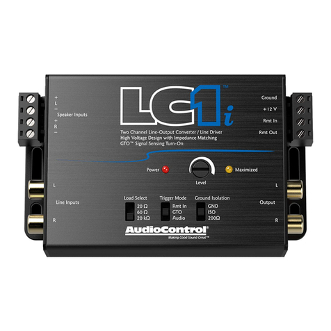
Audio Control LC6i User manual

®
Making Good Sound Great™
Six Channel Line Output Converter
for interfacing with factory installed audio systems
Greengs from the rainforests of the Pacic Northwest. We would
like to congratulate you on your purchase of the LC6i: a six-chan-
nel, high-performance, line-output converter. This unique product
will accept two, four, or six channels of speaker-level signal from
a factory-installed amplier or source unit, and convert it to a
high-quality, low-noise pre-amp signal. Therefore the LC6i is an ideal
OEM (Original Equipment Manufacturer) interface component, as it
will allow you to use your factory-installed source unit but give you the
ability to add really good aermarket amplier(s) and processor(s).
Whether this is your rst product from the rainforest dwellers of Audio-
Control, or you are already a rm believer, you will denitely enjoy how
great the LC6i can make your performance system sound.
Now before you start salivang just thinking about the benets and all
of the niy applicaons for your LC6i, please take a few minutes to sit
back, have a cold beverage, and read through this manual. We always
love to get calls from our customers, but we have tried to answer all of
your quesons in this manual. It contains lots of useful facts and infor-
maon - - and besides, we spent a lot of me wring it!
tmLC6

----------------------------------------------- 2 -----------------------------------------------
Important Safety Instructions
1. Read these instructions.
2. Keep these instructions.
3. Heed all warnings.
4. Follow all instructions.
5. Do not use this apparatus near water.
6. Clean only with a dry cloth.
7. Do not block any ventilation openings. Install in accordance with the manu-
facturer’s instructions.
8. Do not install near any heat sources such as muers, silencers, exhaust
pipes, or other apparatus (including ampliers) that produce heat.
9. WARNING: Improper installation may lead to permanent injury or death.
Installation of the apparatus must be done with great care by qualied per-
sonnel, to prevent damage to fuel lines, power, and other electrical wiring,
hydraulic brake lines, and other systems, that might compromise vehicle
safety.
10. Provide +12V and Ground wiring of a suitable thickness/gauge to ensure
adequate current to the apparatus.
11. Use rubber grommets to protect wiring whenever passing wires through
metal openings or bulkheads.
12. Only use attachments/accessories specied by the manufacturer.
13. Refer all servicing to qualied service personnel. Servicing is required when
the apparatus has been damaged in any way, such as the power input ter-
minals are damaged, liquid has been spilled or objects have fallen into the
apparatus, the apparatus has been exposed to rain or moisture, does not
operate normally, or has been dropped.
14. This apparatus shall not be exposed to dripping or splashing, and no object
lled with liquids, shall be placed on the apparatus.
15. Fuses shall be replaced only with the correct type and fuse value, and only
when the apparatus is powered o.
16. Exposure to high sound pressure levels may lead to permanent hearing
loss. Take every precaution to protect your hearing.

----------------------------------------------- 3 -----------------------------------------------
The lightning ash with arrowhead symbol within an equilateral trian-
gle is intended to alert the user to the presence of uninsulated “danger-
ous voltage” within the product’s enclosure, that may be of sucient
magnitude to constitute a risk of electric shock to persons.
The exclamation point within an equilateral triangle is intended to alert
the user of the presence of important operating and maintenance (ser-
vicing) instructions in the literature accompanying the appliance.
Caution: to reduce the risk of electric shock, do not
disassemble the apparatus, other than to remove
the top panel to access the controls. There are no
user-serviceable parts inside. Refer servicing to
qualied personnel.
Recycling notice: If the time comes and this apparatus has fullled its
destiny, do not throw it out into the trash. It has to be carefully recy-
cled for the good of mankind, by a facility specially equipped for the
safe recycling of electronic apparatii. Please contact your local or state
recycling leaders for assistance in locating a suitable nearby recycling
facility. Or, contact us and we might be able to repair it for you.
Key Features of The LC6i
Here are some of the cool features that your LC6i oers:
• Six input and output channels
• Speaker-level inputs – can accept 400-wa signals!
• Internal channel summing
• GTO™ - signal-sensing inputs
• Level matching controls
• 12 Volt trigger output
• Input for oponal subwoofer level control

----------------------------------------------- 4 -----------------------------------------------
Features and Highlights
Speaker-Level Inputs
If you are like many people who enjoy the look and features of your
factory-installed source unit but feel your system overall is lacking pow-
er and bass, we have good news. The LC6i has high-impedance speak-
er-level inputs that allow it to accept amplied signals from all known
factory-installed source units (even Bose) and output a high-quality
pre-amp signal via standard RCA connectors. This will allow you to add
beer-quality aermarket ampliers, processors and speakers while
keeping the convenient features of your factory-installed source unit.
Unlike inexpensive speaker-level and line-output converters, the LC6i
oers the highest sound quality and can handle the full signal strength
of a 400-wa amplier.
GTO™ Signal-Sensing Inputs
We have equipped your LC6i with our unique GTO™ (Great Turn On)
signal-sensing inputs. Once the GTO input of your LC6i detects a speak-
er-level signal on the Main Inputs, it powers up. When the speaker-lev-
el signal goes away, your LC6i will automacally turn-o. Oponally,
your LC6i is also equipped with a standard 12-Volt trigger (Remote In)
that will allow you to turn on your LC6i in the tradional manner. The
GTO circuit can be disabled by seng an internal jumper.
12-Volt Output Trigger
Since you will be using an external amplier(s) and processor in your
system, you will need the ability to “trigger” or turn-on these devices
(a romanc dinner won’t quite work here). Your LC6i has a high-current
12-Volt output (labeled Remote Out) that will provide a trigger to these
remote devices, when the LC6i is powered up. Please note that this
output is not to be used as the main power for these devices.

----------------------------------------------- 5 -----------------------------------------------
Internal Channel Summing
The LC6i has the unique ability to internally sum together mulple (4 or
6) input channels from the factory source unit into 2 channels. This is
parcularly handy when using the LC6i with a factory system that has
mulple, acvely crossed-over signals being sent from the OEM source
unit or amplier(s). For example, in some vehicles there is an acvely
crossed-over tweeter, midrange, and woofer all in the front of the vehi-
cle. The LC6i lets you take all of those signals and sum them together
to get a high-quality, full-range, pre-amp signal without the use of any
addional cables or hardware. Internal jumpers allow you to sum the
channels 2 and 3 to the main outputs, or keep them separate.
AutoMode Inputs
Somemes in life (and car audio) we need more outputs than inputs.
Therefore we have equipped your LC6i with AutoMode inputs that
take the Channel 2 signal and automacally feeds it to the Channel 3
outputs, provided there is no signal present on the Channel 3 inputs.
This means your LC6i will accept two input channels and give you four
output channels. Or it can accept four input channels and give you
six output channels. The AutoMode can be disabled by moving an
internal jumper.
Output Level Controls
Your LC6i has level controls for each pair of channels. These controls
allow you to adjust the signal level from your factory-installed amplier
or source unit to match up with your aermarket amplier or proces-
sor.

----------------------------------------------- 6 -----------------------------------------------
Input For An Oponal Subwoofer Level Control
With the addion of high performance, aermarket amplier(s) and
speakers, you may feel the need to have more control over your sys-
tem. The Remote Subwoofer Level Control (sold separately along with
undercoang) allows you to add a dash-mounted control to your LC6i
that will adjust the level of the Channel 3 output, oen used for the
subwoofer. This output is full range so it may need to be crossed over
depending upon your applicaon.
Bulletproof Warranty
The most important feature of
all. Every AudioControl product is
selessly designed and manufac-
tured in our factory located in the
rainforests of the Pacic North-
west. We take every eort to en-
sure that you will have many years
of enjoyment out of your LC6i. To
ensure opmal performance we highly recommend that you allow your
authorized AudioControl dealer to perform the installaon. Not only
do they have all the right knowledge and tools, but also in the unlikely
chance your LC6i should stop working, we will back it with a limited ve
years parts and labor warranty. Should you choose to install it yourself
we will sll give you a one-year parts and labor warranty. To acvate
your warranty, you need to FILL OUT AND SEND IN YOUR WARRANTY
CARD!
We also recommend that you save your invoice or sales slip as proof
of installaon and ownership. Not only is it necessary for warranty
purposes, but should your LC6i “walk away” one day while your car is
parked at your local laé stand, you will nd insurance companies very
unforgiving without proof of purchase.

----------------------------------------------- 7 -----------------------------------------------
Quick Installation Information
For those of you who are short on me but high on ambion, we oer
the following secon to speed up your installaon of the LC6i:
1. Physically mount the LC6i in a locaon that keeps it away from
soda spills, food crumbs, and the curious ngers of those you have
wronged. You will want to select a locaon that allows you access
to the level controls. In many cases you can nd factory speaker
leads in the rear of the vehicle that are easy to access.
2. The LC6i needs to be installed in the signal path between your OEM
source unit or factory-installed amplier(s) and an aermarket
external amplier and/or processor(s). Locate the speaker wires
that are coming from your factory source unit and/or amplier and
connect them to the speaker-level inputs on your LC6i.
3. Connect the Output RCA connectors to cables that run to your
aermarket external signal processors and/or ampliers. If this
is not obvious to you, quickly pack up your LC6i and run to your
nearest authorized AudioControl dealer to have them perform the
installaon. You will thank us later.
4. Connect +12V power, ground, and remote turn-on (if applicable).
5. Level match your LC6i to your source and ampliers.
Note: You will want to turn the gains DOWN on your aermarket ampli-
ers to maximize your systems performance and minimize any HISS.
The example on the next page shows the use of the LC6i with an
AudioControl mul-channel power amplier.

----------------------------------------------- 8 -----------------------------------------------
Figure 1: Basic LC6i System
LC-6.1200

----------------------------------------------- 9 -----------------------------------------------
If music be the food of love, play on.
and..if you need to know more, then read on. Heck, if you don’t need
to know more, sll read on, because you can never know too much,
and as much as we would like to get your calls and e-mails, most of the
answers to your quesons are in this manual!

-----------------------------------------------10 ----------------------------------------------
A Guided Tour of the LC6i
9
10 1 6 5 4 3 2
11 8 7
Figure 2: LC6i top cover

-----------------------------------------------11 ----------------------------------------------
1. Speaker-level Inputs: The LC6i has three sets of speaker-level
inputs. These inputs get their signals from the speaker-level
outputs of your factory-installed source unit or amplier (if your
vehicle is so equipped). If your source unit has front, rear, and
subwoofer speaker-level outputs, connect them to the three sets
of inputs on your LC6i. If the source unit only has front and rear
inputs, the Auto Mode circuitry in your LC6i automacally routes
the Channel 2 input channels to Channel 3.
2. Ground: Connect to a good, veried chassis ground (the baery
comes to mind.) Warning: Factory ground wires typically already
have mulple devices connected to them and are not recom-
mended.
3. +12 Volt: Connect to a good source of power (the baery comes
to mind again).
4. Remote In: Allows your LC6i to be turned on remotely with a 12-
Volt signal.
5. Remote Out: Outputs 12 Volts when the LC6i is powered up so
you can turn on external devices like signal processors and exter-
nal ampliers. DO NOT USE FOR SYSTEM POWER!!
6. Maximized Indicator: This brightly colored LED indicates when
your signal level is just below clipping your LC6i. When properly
level matched, this LED should icker occasionally when your
system is playing at its maximum volume level.
7. Power: If you have connected all of your power wires correctly,
this light should be bright red when your system turns on.
8. Remote Subwoofer Level Control Input: This input allows you
to add an oponal (sold-separately-not-included) ACR-1 remote
that will allow you to control the subwoofer output of the LC6i
from your dashboard.

-----------------------------------------------12 ----------------------------------------------
9. Pre-Amp Outputs: These RCA connectors should be connected
to the next component aer the LC6i, such as a signal processor,
crossover or amplier. Do not connect any speakers directly to
your LC6i. (Denitely don’t connect to any home appliances, like
your microwave.)
10. Level Controls: These knobs allow you to adjust the signal level
from your source unit to match that of your aermarket ampli-
ers. Because they are amplied, most factory-installed source
units have relavely high signal voltage output, which will require
you to decrease the signal level.
11. Channel Summed Indicators: Under the cover of your LC6i are
jumpers that will allow you to sum selected channels into the
main channels. This is especially useful for factory-installed sys-
tems with acvely crossed-over speaker systems. These handy
indicator LEDs let you know which channels are being summed
into the main inputs.
Figure 3: Inside view
AutoMode
GTO
Jumper Settings
SUM CH3SUM CH2
Summed
Separate
GND
Isolated
200Ω
Ground
Isolation
TM
Disabled
Enabled

-----------------------------------------------13 ----------------------------------------------
Under the Covers
Make sure all power is OFF before removing the cover. The jumpers
may be pulled out and plugged into an alternave posion to custom-
ize your installaon (see gure 3).
Output Summing Jumpers: These allow you to select which input
signals will be summed into the Main outputs. An LED shows when
channel 2 or 3 is Summed. The factory seng is Separate.
Ground Isolaon Selector: In case alternator noise appears in your sys-
tem, we have provided alternave grounding connecons. Make sure
your system is turned OFF before you move these jumpers.
GTO (Great Turn On) Jumper: Enable or Disable GTO.
AutoMode Jumper: Enable or Disable AutoMode.
Factory Settings – Internal Jumpers
Jumper Factory Seng Opons
Ground Isolaon Isolated 200 Ohm or Ground
Summing Jumpers Separate Summed
GTO Enabled Disabled
AutoMode Enabled Disabled

-----------------------------------------------14 ----------------------------------------------
LC6i Block Diagram
Figure 4: LC6i Block Diagram

-----------------------------------------------15 ----------------------------------------------
Installing Your LC6i
By this me we are sure that you are chomping at the bit to install your
LC6i. Up to this point, everything you have read has served to educate
you on the operaons of LC6i. Therefore if you are sll with us, we
recommend you read the following secons very carefully.
Placement and Mounting of the LC6i
Your LC6i can be physically installed in numerous locaons like behind
your dashboard, under a seat, or even in the trunk/boot. Since you will
be connecng to the speaker wires from the factory source unit or its
amplier(s), you should select a locaon that is convenient for wiring.
Once you have selected a permanent mounng locaon, posion the
unit and mark the appropriate mounng holes with a felt-p pin or
scratch awl.
Before doing anything else, make sure you are not about to drill
a hole in a gas tank or pierce any exisng wiring, fuel lines, or
hydraulic pipes. Nothing ruins your day more than an expensive
repair bill or massive reball.
Drill a few small pilot holes and secure the chassis of the LC6i with
self-tapping screws.

-----------------------------------------------16 ----------------------------------------------
LC6i Power Wiring
WARNING: Failure to disconnect the negave terminal of your
baery prior to the installaon of your LC6i can result in a warm
ngly feeling.
(+12V) Posive Connecon: Insert a 12 to 18 gauge wire into the
connector labeled “+12” on the niy connector of your LC6i. Connect
it to a good constant source of 12 Volts (we suggest the baery), fused
at 1 amp.
Ground Connecon: Use the same gauge wire as you did for the posi-
ve connector and run it from the “Ground” connector on your LC6i to
the negave terminal of the baery, a ground bus, or a veried ground
locaon. The factory head unit ground is not a good ground!
Remote In: Connect a 22 to 18 gauge wire from the source unit’s re-
mote turn-on or other trigger to the Remote connector on the LC6i. As
we previously menoned, your LC6i is equipped with GTO signal sens-
ing which allows it turn on when it detects a signal at the Main speak-
er-level inputs so you may not need to use the “Remote In” feature.
Remote Out: If you are going to use the LC6i to turn on any external
signal processors or ampliers, connect an 18 to 22 gauge wire from
the Remote Out on the LC6i to the remote turn-on of the processors or
ampliers. The remote output is relay operated and capable of 1 Amp
out.
Once the electrical connecons are complete, you will want to recon-
nect the negave terminal to your baery, however connue to act
posively.

-----------------------------------------------17 ----------------------------------------------
LC6i Audio Wiring
The LC6i needs to be installed in the signal path aer your factory
source unit or amplier but denitely before your aermarket ampli-
ers and/or any signal processors. You may already have guessed there
are numerous ways to congure the LC6i in your audio system so we
recommend you spend a lile quality me planning out your system
and even sketching it out on paper.
The next 2 pages show some examples of using the LC6i with some of
our mul-channel ampliers and subwoofer ampliers.

-----------------------------------------------18 ----------------------------------------------
Interfacing with a factory-installed radio
Figure 5: LC6i system using summing funcons – 2-way front plus subwoofer
45 150
10070 85
ACR-1
LC-4.800
LC-1.800

-----------------------------------------------19 ----------------------------------------------
Figure 6: Six channel system with LC6i and EQS
LC-6.1200

-----------------------------------------------20 ----------------------------------------------
Speaker-Level Inputs
The LC6i is designed to accept an amplied, speaker-level signal from
a factory source unit or amplier. You will want to refer to a facto-
ry service manual or wiring-harness schemac to determine which
wires are the speaker wires for your system. If you are unsure which
wires are the speaker wires, it is recommended you look at the color
of the speaker wire connected to the speakers and follow them back
to the factory source or amplier. Connect the speaker wires to the
Speaker-Level Inputs on your LC6i. Make sure to get your “pluses” and
“minuses” connected properly.
Pre-Amp Outputs
Connect good quality RCA connectors from these outputs to the inputs
of your ampliers. While we won’t get into the discussion as to wheth-
er plutonium cables sound beer than un-obtainium cables we will
tell you that well-constructed cables are less problemac in a rugged
environment like your car system.
Other manuals for LC6i
1
Table of contents
Other Audio Control Media Converter manuals

Audio Control
Audio Control DQ-61 User manual
Audio Control
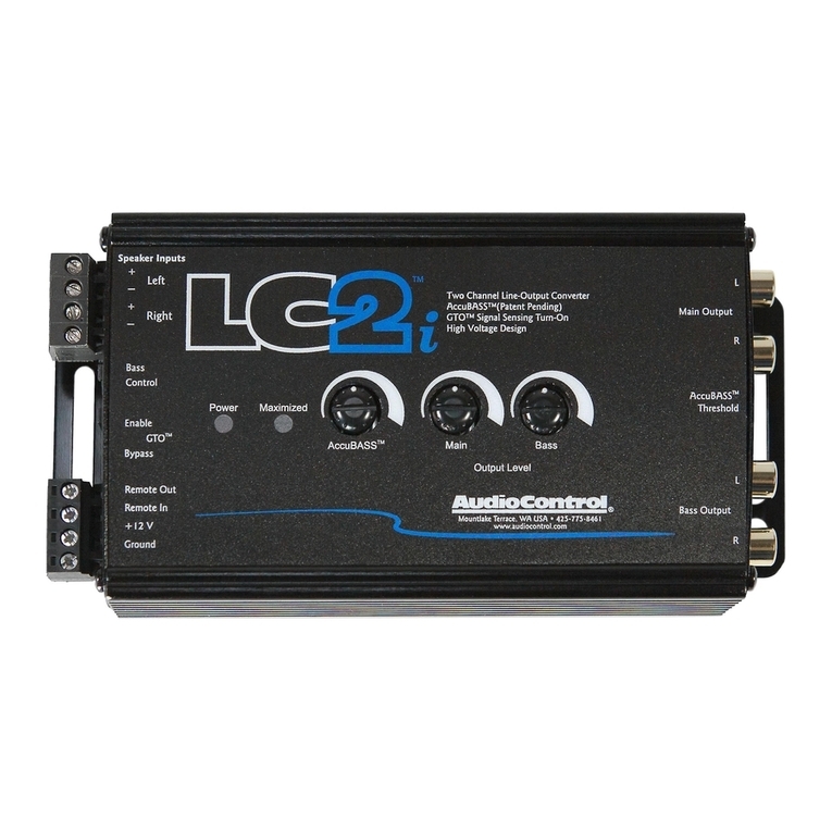
Audio Control LC2i User manual

Audio Control
Audio Control LC6i User manual

Audio Control
Audio Control DQ-61 User manual

Audio Control
Audio Control LC6 User manual
Audio Control
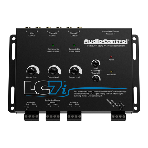
Audio Control LC7i User manual
Audio Control
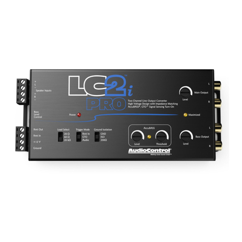
Audio Control LC2i PRO User manual

Audio Control
Audio Control LCQ-1 User manual
Audio Control
Audio Control LC5i PRO User manual
Audio Control
Audio Control LC7i User manual
