Audio Precision AECM206 User manual

AECM206
headphone test fixture
User’s Guide and Specifications
November, 2017
model AECM206

Copyright © 2011–2017 Audio Precision, Inc.
All rights reserved.
Printed in the United States of America.
No part of this manual may be reproduced or transmitted
in any form or by any means, electronic or mechanical, in-
cluding photocopying, recording, or by any information
storage and retrieval system, without permission in writing
from the publisher.
Audio Precision, AP, and APx are trademarks of Audio
Precision, Inc. Windows™ is a trademark of Microsoft Cor-
poration. Dolby and the double-D symbol are trademarks
of Dolby Laboratories, Inc. DTS is a trademark of DTS, Inc.
pn 8211.0354 rev 000 XVII1114095536
Audio Precision
5750 SW Arctic Drive
Beaverton, Oregon 97005
503-627-0832
800-231-7350
ap.com

Documentation and Support
This booklet contains a user’s guide and full specifications for the Audio Precision
AECM206 Headphone Test Fixture. The AECM206 is an acoustic accessory that requires
ICP® powering for its internal microphones, and typically requires an audio analyzer such as
an Audio Precision APx5 Series for signal measurement and analysis.
ap.com
Visit the Audio Precision web site at ap.com for APx support information and APx
resources. You can also contact our Technical Support staff at techsupp[email protected], or by
telephoning 503-627-0832 ext. 4, or 800-231-7350 ext. 4 (toll free in the U.S.A.).
Serial Numbers
The internal microphones and preamplifiers are mated and calibrated as a pair, and must
be maintained as a pair for the TEDS calibration to remain valid. Record your serial numbers
here for reference.
AECM206 Headphone Test Fixture sn ______________________________
Left Ear Usage (blue cable marking)
AECM304 Occluded Ear Simulator sn ______________________________
(with embedded microphone)
426M15 preamplifier sn ______________________________
Right Ear Usage (red cable marking)
AECM304 Occluded Ear Simulator sn ______________________________
(with embedded microphone)
426M15 preamplifier sn ______________________________


AECM206 Headphone Test Fixture: Table of Contents i
Table of Contents
User Guide . . . . . . . . . . . . . . . . . . . . . . . . . . . . . . . . . . . . . . . . . . . . . . . . . . . . . . . . . . . . . . . 1
Overview. . . . . . . . . . . . . . . . . . . . . . . . . . . . . . . . . . . . . . . . . . . . . . . . . . . . . . . . . . . . . . . . . 1
What’s in the box?. . . . . . . . . . . . . . . . . . . . . . . . . . . . . . . . . . . . . . . . . . . . . . . . . . . . . . . . . . . . 2
Inspection and preparation . . . . . . . . . . . . . . . . . . . . . . . . . . . . . . . . . . . . . . . . . . . . . . . . . . . . . . . 3
Removal from packaging . . . . . . . . . . . . . . . . . . . . . . . . . . . . . . . . . . . . . . . . . . . . . . . . . . . . . . . . 3
Components. . . . . . . . . . . . . . . . . . . . . . . . . . . . . . . . . . . . . . . . . . . . . . . . . . . . . . . . . . . . . . . 3
Pinnae part numbers . . . . . . . . . . . . . . . . . . . . . . . . . . . . . . . . . . . . . . . . . . . . . . . . . . . . . . . . . . 5
Orientation. . . . . . . . . . . . . . . . . . . . . . . . . . . . . . . . . . . . . . . . . . . . . . . . . . . . . . . . . . . . . . . . 5
Attaching the pinnae. . . . . . . . . . . . . . . . . . . . . . . . . . . . . . . . . . . . . . . . . . . . . . . . . . . . . . . . . . . 6
Connection to analyzer . . . . . . . . . . . . . . . . . . . . . . . . . . . . . . . . . . . . . . . . . . . . . . . . . . . . . . . . . 6
Powering. . . . . . . . . . . . . . . . . . . . . . . . . . . . . . . . . . . . . . . . . . . . . . . . . . . . . . . . . . . . . . . . . 6
TEDS . . . . . . . . . . . . . . . . . . . . . . . . . . . . . . . . . . . . . . . . . . . . . . . . . . . . . . . . . . . . . . . . . . 6
Factory Calibration. . . . . . . . . . . . . . . . . . . . . . . . . . . . . . . . . . . . . . . . . . . . . . . . . . . . . . . . . . . . 6
Local Calibration. . . . . . . . . . . . . . . . . . . . . . . . . . . . . . . . . . . . . . . . . . . . . . . . . . . . . . . . . . . . . 7

Chapter 1: Table of Contents
ii AECM206 Headphone Test Fixture: Table of Contents
Test Use Case. . . . . . . . . . . . . . . . . . . . . . . . . . . . . . . . . . . . . . . . . . . . . . . . . . . . . . . . . . . . . . 9
Service . . . . . . . . . . . . . . . . . . . . . . . . . . . . . . . . . . . . . . . . . . . . . . . . . . . . . . . . . . . . . . . . .10
Removing the alignment ring plate . . . . . . . . . . . . . . . . . . . . . . . . . . . . . . . . . . . . . . . . . . . . . . . . . . . 10
Removing the preamplifier/microphone system from the head . . . . . . . . . . . . . . . . . . . . . . . . . . . . . . . . . . . . . 10
Removing the preamplifier/microphone system for shipping . . . . . . . . . . . . . . . . . . . . . . . . . . . . . . . . . . . . . . 11
Separating the preamplifier from the microphone . . . . . . . . . . . . . . . . . . . . . . . . . . . . . . . . . . . . . . . . . . . . 11
Removing the head from the neck. . . . . . . . . . . . . . . . . . . . . . . . . . . . . . . . . . . . . . . . . . . . . . . . . . . .12
Reinstalling the preamplifier/microphone system and cable. . . . . . . . . . . . . . . . . . . . . . . . . . . . . . . . . . . . . . . 14
Specifications . . . . . . . . . . . . . . . . . . . . . . . . . . . . . . . . . . . . . . . . . . . . . . . . . . . . . . . . . . . . .15

AECM206 Headphone Test Fixture: User’s Guide 1
User’s Guide
Overview
The AECM206 is a well-isolated headphone test fixture that
supports standards-compliant headphone, earphone, earbud
and hearing protection (ear muff) testing.
Symmetrical, anatomical pinnae are provided in two hard-
nesses, accommodating circum-aural, supra-aural, intra-
concha, and insert earphone testing.
In the head of the fixture are two AECM304 ear simulators
(acoustic couplers with built-in measurement micro-
phones). Each AECM304 is fitted with an ear canal exten-
sion and connected to a 426M15 preamplifier and cable.
The fixture is stabilized and mounted on a steel base that
helps to isolate mechanical vibrations during testing.
The AECM206 complies with applicable portions of the
International Standards ISO 4869-3 and IEC 60318-4.

User’s Guide
2 AECM206 Headphone Test Fixture: User’s Guide
What’s in the box?
The AECM206 is delivered surrounded by protective contoured foam, shipped in either a cardboard carton or an optional hard
travel case. The fixture is fully assembled and ready for immediate use.
Figure 1. AECM206 as packaged for shipment
Cases for
AECM304
shipping
Cases for
426M15
shipping
Pinnae
Shore A-25
Pinnae
Shore OO-35
Fixture
lifting sling
Tools and
silicon
grease
Headphone
Test
Fixture
USB drive
documents
ADP105
adapter
for
CAL250
Space for
optional
CAL250
Coiled mic
cables

User’s Guide
AECM206 Headphone Test Fixture: User’s Guide 3
Inspection and preparation
Removal from the packaging
See Figure 1. The test fixture is protected for shipment by
contoured foam in a strong carton or hard travel case. The
fixture must be removed with care. For this purpose, a sling
is provided. Pull the sling upwards with one hand while eas-
ing the base of the test fixture out of the case with the other
hand.
Carefully remove the coiled audio cables from their cavity.
Be sure to carefully coil the cables, and to encircle the test
fixture with the sling when replacing it into the foam cutout.
To carry the AECM206, support both the neck and head
simultaneously.
Components
The headphone test fixture consists of a massive tubular
head, fitted on a neck, which is connected to a circular base.
The head encloses an internal cavity where the ear simula-
tor/preamplifier assemblies are mounted. The hat provides a
support for the headband provided with most headphones.
The AECM304 ear simulator is fitted with an internal mea-
surement microphone and is threaded for attachment to the
426M15 preamplifier. Each AECM304/426M15 assembly
is a mated pair, calibrated together. The components must
not be interchanged between assemblies.
At the acoustic end, each AECM304 is fitted with an ear
canal extension. The ear canal extensions project slightly
from the right and left side ends of the head. An alignment
ring plate is mounted on each end, to secure the pinnae and
aid in alignment when mounting headphones. See Figures 2
through 6.
Figure 2. Headphone Test Fixture key components
Face
Alignment
ring plate
Alignment
stud
Hat
Head
Neck
Neck cavity
(located in back)
Base
Collar
Preamplier
cables

User’s Guide
4 AECM206 Headphone Test Fixture: User’s Guide
Figure 3. AECM206-RING alignment ring plate and screws.
Two such rings are mounted on the AECM206.
Figure 4. ADP105 Adapter for CAL250.
Figure 5. 2.5 mm, 2 mm and 1.5 mm hex drivers; silicon
grease.
Figure 6. An AECM304, shown here fitted with an
ear canal extension to the left in the photograph, and mated
to an 426M15 preamplifier, shown to the right. Two such
assemblies are mounted within the AECM206 head.

User’s Guide
AECM206 Headphone Test Fixture: User’s Guide 5
Ear Simulator and Preamplifier
As mentioned, the AECM304 ear simulator and the
426M15 preamplifier are a mated pair that must be used
together for the calibration and TEDS data to be valid.
The small cases provided for these components carry the
part number and serial number, and are also labeled with the
part number and serial number of the paired component.
See Figure 7. Do not interchange these components.
Figure 7. Example of serial number pairing labels.
Pinnae part numbers
Each pinna is labeled with a part number that designates left
or right usage, and the hardness by the Shore rating scale.
Orientation
For orientation purposes, the face of the test fixture head is
associated with the Audio Precision logo. Therefore, when
the fixture is set with the logo facing you, the left pinna and
internal ear simulator are to your right, and the right pinna
and internal ear simulator are to your left.
The cable connected to the left ear simulator/preamplifier is
indicated by a blue marker at the BNC connector, and the
cable connected to the right ear simulator/preamplifier is
indicated by a red marker.
Figure 8. Headphone Test Fixture orientation
For use with
AECM304 sn 1014
426M15 sn 482
MATCH
MATCH
AECM304 sn 1014
For use with
426M15 sn 482
Part Number Usage Hardness
AEC-LOO35 Left Shore OO-35
AEC-ROO35 Right Shore OO-35
AEC-LA25 Left Shore A-25
AEC-RA25 Right Shore A-25
Right pinna
(mic connected
to red cable)
Left pinna
(mic connected
to blue cable)
Face

User’s Guide
6 AECM206 Headphone Test Fixture: User’s Guide
Attaching pinnae
You may remove the ring plate to fit the pinnae to the head
and then replace the ring plate, or you can fit the pinnae
without removing the ring plate by carefully pressing and
tucking the base of each pinna into the shallow cavity
behind the ring. In either case, be sure to line up the key slot
at the bottom of each pinna to the alignment stud in the
head, as shown in Figure 9.
Figure 9. Aligning the pinna.
To remove the pinnae, you can first remove the ring plates,
or you can gently pull each pinna out from under the ring,
being sure to grip the whole pinna so as not to damage it.
The Shore OO-35 pinnae are Type 3.3 pinna simulators,
recommended for measurements on all types of devices.
The Shore A-25 pinnae are a Type 3.3 style with a Type 3.4
hardness. They are provided as a harder alternative, com-
pressing to a lesser extent when using supra-aural or other
compressing headphones.
Connection to an analyzer
Powering
Use the two BNC-terminated coaxial cables to connect to
the unbalanced inputs of an audio analyzer (blue to left, red
to right), via suitable microphone powering. The preampli-
fiers within the headphone test fixture require ICP® (IEPE)
constant current power (CCP). This may be provided by
using a suitable power supply, such as the Larson Davis
480B12, available from Audio Precision. Another excellent
solution is the Audio Precision APx1701 Transducer Test
Interface, which provides constant current power for the
microphones and also a precision power amplifier to drive
the headphone transducers.
TEDS
The preamplifiers are programmed with identification infor-
mation and results of the latest factory calibration, encoded
as TEDS (Transducer Electronic Data Sheet) data. The cali-
bration information is specific to each ear simulator/pream-
plifier assembly. These comprise a mated pair and should
not be interchanged with the components of another assem-
bly.
Many devices (including the Audio Precision APx1701
Transducer Test Interface) can read embedded TEDS data.
Calibration
Factory Calibration
We recommend that the AECM206 be returned to the fac-
tory for calibration and certification as part of a regular ser-
vice program.

User’s Guide
AECM206 Headphone Test Fixture: User’s Guide 7
Alternatively, the paired AECM304/426M15 assemblies
can be removed from the head and returned to the factory
together for calibration. Small cases are provided for this
purpose. For information on removal, see “Removing Pre-
amplifier and Ear Simulator” on page 10.
In either case, the TEDS for each AECM304/426M15
assembly will be updated using the latest factory calibra-
tion information.
Local Acoustic Level Calibration
In daily use, a local acoustic level calibration is typically
performed frequently, perhaps at the beginning and end of
each day, or even with each test. This ensures accurate test-
ing levels in the local environment.
If local level calibration is not available, the TEDS data
embedded in each AECM304/426M15 assembly can be
used.
To calibrate the acoustic level for the Headphone Test Fix-
ture, you must use a Larson Davis CAL250 calibrator. The
CAL250 is an option you can purchase through Audio Pre-
cision. An ADP105 adapter is provided with the Head-
phone Test Fixture, and must be securely attached to the
CAL250. The ADP105 is fitted with gaskets to assure a
good acoustic seal with both the CAL250 and the Ear Canal
Extension fitted to each AECM304.
Note: if the CAL250 has an ADP019 adapter
already fitted, the ADP019 must be removed
before attaching the ADP105.
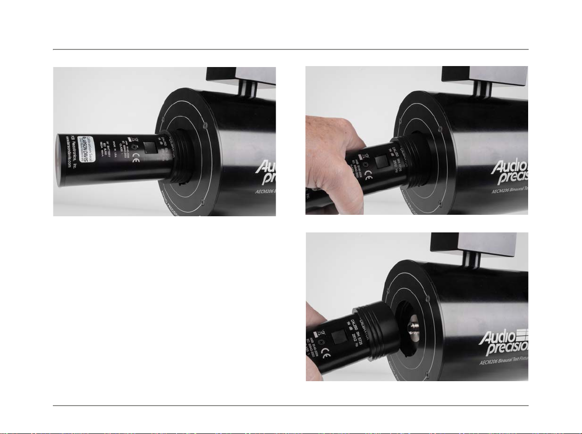
Figure 10. CAL250 shown with ADP105 unattached,
and with ADP105 attached for use.
Calibrate each side of the Headphone Test Fixture. Place
the CAL250 with ADP105 on the ear canal extension of the
internal ear simulator, and push it firmly into place to estab-
lish an acoustic seal, as shown in Figure 11. The coaxial
output cable for that ear simulator/preamplifier assembly
should be connected to a power supply and analyzer input.
The CAL250 calibrator’s acoustic output is 114 dBSPL
(10 Pa) at 251.2 Hz.
User’s Guide
8 AECM206 Headphone Test Fixture: User’s Guide
Figure 11. CAL250 attached to the AECM206
Push the button on the calibrator to turn it on. The CAL250
will run for 60 seconds, which provides sufficient time for
you to measure and set the calibration level in your ana-
lyzer. When calibration is complete, carefully remove the
calibrator from the ear canal extension, pressing down to
release the gasket seal before pulling the calibrator away, as
shown in Figures 12 and 13.
Repeat this procedure to calibrate the opposite side of the
Headphone Test Fixture.
Figure 12. Pressing down to release gasket seal.
Figure 13. Removing the calibrator.

User’s Guide
AECM206 Headphone Test Fixture: User’s Guide 9
Test Use Case
Figure 14 shows a block diagram of a basic headphone test, using the AECM206 Headphone Test Fixture, an Audio Precision
analyzer and the Audio Precision APx1701 Transducer Test Interface.
This figure is representative: a different audio analyzer could be used, and the functions of the APx1701 could be replaced by
an audio power amplifier and a two-channel ICP® microphone power supply.
Figure 14. AECM206 test use case
POWER
AMPLIFIER
OUTPUTS INPUTS
ANALOG OUTPUTS ANALOG INPUTS
MIC
INPUTS MIC
PASS THRU CURRENT
SENSE
Windows Computer
USB
USB
(Phantom) (CCP)
APx1701 Transducer Test Interface
APx500
Ground Strap
SW
Switches
Headphone Test Fixture
Any
APx Analyzer
Acoustic Headphone Test
using the APx1701
and AECM206
LR

User’s Guide
10 AECM206 Headphone Test Fixture: User’s Guide
Service
The AECM206 Headphone Test Fixture does not require
regular maintenance. Keep the fixture clean and dust-free.
We recommend regular factory calibration for the left and
right ear simulator/preamplifier assemblies. You can ship
the entire Headphone Test Fixture to the factory; or, you
may find it simpler to remove the two ear simulator/pream-
plifier assemblies (with attached cables) and return them for
calibration using the small cases provided.
If a preamplifier/ear simulator assembly, cable, or other
component is lost or damaged, contact our service depart-
ment at serv[email protected] for parts or service.
Disassembly
Removing the alignment ring plate
Figure 15. Removing the AECM206-RING.
The AECM206-RING alignment ring plate is attached to
the fixture by four 2.5 mm screws. It is easily removed by
removing the screws using the provided 2 mm hex wrench.
When re-attaching, secure the ring using the four screws.
Do not over-tighten.
Removing the preamplifier/ear simulator system
from the head
Each mated AECM304/426M15 assembly is clamped into
the fixture, secured by a recessed set screw available on the
rear of the fixture. Using the 2.5 mm hex wrench, back the
set screw partially out by turning it counter-clockwise until
two or three threads are visible, as shown in Figure 16.
Figure 16. Location of clamp set screws.
Gently pull the AECM304/426M15 assembly out of the fix-
ture, as shown in Figure 17. If a tool is required, use pliers
with non-marring (plastic or rubber) jaws. Be sure that the
attached cable glides freely through the head. If the cables

User’s Guide
AECM206 Headphone Test Fixture: User’s Guide 11
cannot be pulled easily, remove the head from the neck as
described on page 12.
Figure 17. Removing the ear simulator/
preamplifier assembly.
Removing the ear simulator/preamplifier assem-
bly for shipping
To completely remove the preamplifier/ear simulator
assembly and cable for shipping, you must first separate the
426M15 preamplifier from the AECM304, and then remove
the fixture head from the neck to free the cables from the
acoustic isolation material.
Separating the preamplifier from the
ear simulator
Once the clamp has been loosened (Figure 16) and the
AECM304/426M15 assembly has been pulled out of the
head (Figure 17), gently unscrew the AECM304 from the
426M15 as shown in Figure 18. To protect the threads on
the 426M15, you may place a rubber boot (found in the pre-
amplifier plastic case) over the threads, as shown in Figure
19.
Figure 18. Separating the preamplifier and ear simulator
Figure 19. Protective rubber boot on preamplifier threads

User’s Guide
12 AECM206 Headphone Test Fixture: User’s Guide
Removing the head from the neck
Two set screws in the stainless steel collar of the head
secure the head to the neck, as shown in Figure 20. Use the
2.5 mm hex wrench to remove the two set screws.
Figure 20. Set screws securing the head to the neck.
Since both the head and the stand (the neck/base assembly)
are heavy and unwieldy, care must be taken that the audio
cables are not pulled or crimped.
Hold the base down with one hand and pull from the hat to
separate the head and the neck, as shown in Figure 21.
There is a tight acoustic seal between the head and the neck,
requiring considerable force to separate the two. Avoid
twisting, which may cause the cables to break.
Carefully remove the head from the neck and set it along
side the stand. If there is not enough slack in the cables to
allow you to set the head next to the stand, lay the stand on
its side until you can release the cables.
Lay the head and neck/base assembly on a table as shown in
Figure 22, pulling sufficient cable through the acoustic iso-
lation material so that there will not be a strain on the
cables.
Figure 21. Separating the head from the neck.

User’s Guide
AECM206 Headphone Test Fixture: User’s Guide 13
Figure 22. If necessary, lay the stand and head down
together until you can loosen the cables.
In the neck, the audio cables are tucked into a crevice in the
rubber barrier and acoustic isolation material, as can be seen
in Figure 23. Gently pull the wires from the gasket by pull-
ing away from the stand. If they don’t come loose easily,
use a hex driver to remove the washer and gasket, then gen-
tly pull the cables out of the gasket.
If you have already separated the AECM304 from the
426M15 as discussed on page 11, you will now be able to
pull the cable and the attached 426M15 down through the
head and neck collar and remove it.
Alternatively, if the AECM304/426M15 assembly is still
mounted in the head, you can gently pull the assembly com-
pletely out of the head, as shown in Figure 17. Feed the
cable and BNC connector up through the head and out the
side.
Separate the 426M15 from the AECM304 by unscrewing
the two devices, as shown in Figure 18. Do not remove the
ear canal extension.
Figure 23. Slip the cables through the slot in the gasket and
then pull the cables up through the opening in the neck.

User’s Guide
14 AECM206 Headphone Test Fixture: User’s Guide
Reassembly
Reinstalling the preamplifier/ear simulator
system and cable
Ensure the correct AECM304 and mated 426M15 are to be
installed on the correct side. See Orientation on page 5.
NOTE: It is important to follow these steps
exactly to ensure the quality of the acoustic test-
ing.
Connect AECM304 to 426M15 preamplifier by pushing
together and screwing hand tight.
With head disconnected from the neck, feed the cable/BNC
connector through the head cavity down out the neck col-
lar, pulling all the cable through and finally inserting the
attached AECM304/426M15 assembly into the head. Push
the AECM304 in until set.
Figure 24. Removing the neck washer and gasket.
Using the 2.5 mm hex driver, unscrew the washer/gasket
screw completely. Pull off assembly, and then separate the
washer from the gasket, as shown in Figures 24 and 25.
Place the head next to the stand.
Figure 25. Separating the washer from the gasket.
Measure approximately six inches of cable starting from the
neck insert and running down, and at that spot gently push
the cables into the gasket as shown in Figure 26. The length
of cable between the gasket and neck insert should be
approximately 6 inches.
Table of contents
Other Audio Precision Test Equipment manuals

Audio Precision
Audio Precision ATS-2 User manual

Audio Precision
Audio Precision Portable One Dual Domain User manual

Audio Precision
Audio Precision ATS-2 User manual

Audio Precision
Audio Precision 2700 Series User manual

Audio Precision
Audio Precision System Two User manual

Audio Precision
Audio Precision ATS-1 User manual

Audio Precision
Audio Precision Portable One Plus Access User manual


