Western Instruments WC-9UW User manual

WC-9UW 1
26509 Township Road 543 Phone: (780) 459-6720
Sturgeon County, Alberta Fax: (780) 459-7837
Web: www.westerninstruments.com
Operating Instructions May, 2005
WC-9UW
Underwater Cordless DC Yoke
Established 1965
Established 1965

WC-9UW 2
The WC-9UW allows the Operator to induce a Pulsing DC inspection field
(125Hz) into the ferrous material being tested. The unit is tested to Pressures of
75 PSI (150 below sea level) for extended periods. The device should be utilized
within the parameters set by the operational specifications within this guide.
1. Switch System
The WC-9UW is activated by means of the Module Switch Plunger Assembly.
A small, sealed, WC-Series Switch is mounted on the special Switching
Module, which pulses the 13.2 DC Battery Voltage as it delivers it to the coil
encapsulated in the Yoke housing. To activate this switch, the operator
simply rotates the Switch Plunger approximately ¼ turn.
When installing the Battery Pack, after charging, fit the Switching Module into
the connector at the bottom of the Junction Tube. Ensure the Urethane
Spring is positioned in the bottom of the Junction Tube, and line up the
Connectors in the bottom of the Junction Tube and on the Switching Module.
Then Carefully slide the Battery Pack into the Junction Tube, feeling the
mating connectors together. After the Battery Pack is in place, simply hand
tighten the 4, 10-24 x ¼” fasteners to retain the Battery Pack to the Junction
Tube. Press the Switch Plunger into the Battery Pack, until it stops against
the threads cast inside the Pack housing. Carefully rotate the Plunger until
the handle is about 3/8” from the end of the Battery Pack housing. Place the
¼ Turn
Switch Plunger
Battery Pack
13.2Volts
1.5 Amp Hour
Crack Orientation
Junction Tube
Urethane Spring Switch Module Urethane S
p
acer
Slug protects Spacer
from Plunger
Battery Pack,
Plunger Not Shown
Battery O-Ring, retained
by Battery Collar.
Battery Pack
4, 10-24 x ¼”
Retainin
g
Fasteners

WC-9UW 3
WC-9UW on steel. Then slowly turn the Plunger down until the Yoke
activates, then back of the plunger at least ½ turn. The unit is now ready for
inspection.
Switch Plunger
2. Integral 13.2 Volt Battery Pack The 13.2 VDC Nickel Metal Hydride
Battery Pack has been specially manufactured for the WC-9UW Yoke, and no
attempt should be made to replace or operate this unit with one manufactured
by others, as it will void it’s Class 1, Division II status, and could cause it to
fail at pressure. When operating the WC-9UW in a Hazardous Environment,
the unit must be removed to a Safe Area, for battery Testing or Charging. A
Safe Area is defined as an environment where no risk of explosion exists
(e.g. Facility Offices).
Battery Pack Assembly
When installing the Battery Pack, after charging, cleaning, or maintenance, fit
the Switching Module into the connector in the bottom of the Junction Tube.
Ensure the Urethane Spring is positioned in the bottom of the Junction Tube,
and line up the Connectors in the bottom of the Junction Tube and on the
Switching Module. Carefully slide the Battery Pack into the Junction Tube,
feeling the mating connectors together. Install the retaining fasteners,
followed by the Plunger Assembly.
Battery Testing
The Battery is tested with the WC-9UW Battery Voltage Meter. The meter is
equipped with a load resistor, so a true measure of the Battery Voltage can
be attained. To test the Battery Voltage, insert the Battery Voltage Meter into
the connector cast into the Battery Pack. The Battery Meter provides a
general reading of the Voltage, but also provides the operator with a general
indication of the Battery Capacity or an indication of how much longer the unit
Battery Pack Assembly
Switch Plunger Hole
(Spacer and Plug not shown)
Urethane Spring
under Module,
not shown.
Matting Battery
Co
n
ecto
r
s
Handle
¼ - 20 x 3 3/8”
Sta
inl
ess
Stee
l
2, 0.150” x 0.290” x 0.070” –
ID/OD/Dia. O-Rings.
42mm x 48mm x 3mm O-Ring

WC-9UW 4
may be used for. The WC-9UW will lift 50 pounds with as little as 11 Volts,
as indicated by the Battery Meter. As the Battery Meter is equipped with a
Load Resistor, which simulates the energy draw for the WC-9UW, it should
only be connected for a very short time. If the Battery Meter is left on the
Battery Pack, it will drain a fully charged battery is about 2 hours.
Battery Charging
Western Instruments 1.5 Amp Hour Battery Pack should only be charged with
the Charger supplied by Western Instruments. Batteries should not be left
on charge indefinitely, however, Western Instruments’ Smart Charger will not
typically damage a Battery Assembly if it left charging the Battery for more
than the specified time. Batteries should not be stored when at a low charge
state, with 14 hours required to fully charge the Battery Pack. The operator
plugs the Charger’s 13.2-Volt Connector into the Receptacle on the Battery
Pack, and should note if the Red Charging LED comes on.
Do not attempt to charge the Battery Pack with any other type of charger.
Specifically, any type of ‘fast’ charger may cause the cells in the pack to emit
hydrogen, and will drastically shorten their capacity and life. The charger
provided is designed to automatically reduce it’s current to a ‘trickle’ after the
pack is fully charged. Furthermore, the Green Charged LED will glow when
the battery pack is fully charged.
Note: WC-9UW and WC-9UWK Yokes are identical, with the only difference being the charger
voltage.
The battery condition can be tested with the WC-9UW Battery Voltage Meter
as outlined above. The WC-9UW will lift 50 Pounds (22.7Kg) with as little as
11 Volts of power left in the battery. Battery Duration Tests are routinely
Battery Charger
Charging Current LED
Charger Connector
Battery Pack
Battery Meter measuring
Battery under load.
Inserting Meter
into Batter
y
Plu
g

WC-9UW 5
performed by Western Instruments to test Product Performance, however are
far more demanding than typical field inspections, as units are typically not
activated on a continuous basis (see Operational Parameters). The lift
capabilities of the WC-9UW can be easily confirmed with 5 Pull Test Bars, of
10 Pounds (4.54Kg) each, such as 5 of Western Instruments’ W-PT,
fastened together.
Battery Removal
When the Battery Pack needs to be removed, for cleaning or charging,
remove The Switch Plunger, followed by all 4 of the 10-24 retaining fasteners.
Carefully slide the Battery Pack out of the Junction Tube, immediately drying
and cleaning all components.
Extended Duty Kit
The Extended Duty Kit, simply consists of an Extra Battery Pack. Follow the
above instructions, substituting the extra Battery for the spent one.
3. Operational Parameters –The Operational Parameters or Duty Cycle
for the operation is set to avoid damage to the internal coil or the Output
Module, and must be observed.
Pulsed DC Operation: It is recommended that the operator does not keep
the Yoke on for more than 2 minutes at a time. This activation time should be
followed by an equal time off. This 50% duty cycle is set not to protect the
Coil or the Electronic Module, but is imposed to avoid rapid draining of the
Battery Pack. A fully charged Battery Pack will last 2 hours under continuous
activation, which equates to approximately an 8 hour shift of ‘maintenance’
inspection (as per Western Insturments’ Battery Duration Tests). The battery
condition can be tested with either of the WC-9’s Battery Voltage Indicators
as outlined above.
Typical operation is 5 - 15 seconds on, while applying inspection media,
followed by 5 - 15 seconds off repositioning the Yoke to the target area.
If the Yoke is used for prolonged periods of time such as 2 to 3 hours of
continuous cycling, as outline above, the Yoke will get warm. If the WC-9 is
used in this manner the operator must provide time for a sufficient cooling
period, or components in the Electronic Control Module may fail.
4. Field Characteristics
Pulsing DC Field – The Pulsed DC (125 Hz) Magnetic Field is stronger than
an AC Field and tends to penetrate the workpiece more deeply, however DC
is still sensitive to surface defects. Inspection media tends to adhere to the
entire target area of the workpiece, due to the reduced particle mobility. Dry
Particles may need to be ‘blown off’ to fully reveal an indication, while Wet
method requires more careful application of the bath. The intensity of a DC
Field, by it’s nature, is fixed but the Yoke does Pulse the field providing some
stimulus for the particles to migrate to defects.

WC-9UW 6
It must be noted that there is no demagnetization provision on the WC-9UW,
so parts will have some residual field in them after inspection. The workpiece
can be tested with a Magnetic Field Indicator, such as the W-Series W-FI, to
measure the residual magnet field.
5. Operation:
Position the Pole Pieces (Feet) on the work piece. The area between the
pole pieces is your target area, which also extends laterally out,
approximately 1.5” (38mm), from either edge of the pole pieces. The Field
will expose defects that are transverse to the centerline between the Pole
Pieces. The Pole Pieces should be positioned so that as much of their
contact surfaces as possible, are on the work piece. The Yoke is then
energized, by pressing Push Button Switch, and Magnetic particles are
applied. Dry Method Particles are dusted between the Pole Pieces and over
the target area, while Wet Method Particles are sprayed in a similar manner.
The Target Area is then inspected visually for a collection of Particles around
defects. A Black Light is used to aid visual inspection when Fluorescent
Particles are used. Indications found with Dry Powder will tend to form
immediately, and will take slightly longer with Wet Method Particles. If the
typical direction of defects is not known, rotate the Yoke through 90º and
repeat the inspection of the target area.
The WC-9 produces a standard amount of Field Blow as other DC Yokes.
Field Blow is a collection of Inspection Media between the Pole Pieces,
transverse to the centerline between the Pole Pieces, and may cause a
masking of indications. Field Blow can be minimized by extending the Pole
Pieces farther apart, If work piece configuration does not permit extending
Pole Pieces, reduce the contact area of the Pole Pieces on the workpiece.
Follow the Operational Parameters outlined in these instructions
6. Maintenance – While performing maintenance, or cleaning, the Yoke
should be disconnected from any power source, with safe industrial
practices employed.
After use the Yoke should be fully disassembled and cleaned with a mild
soap solution, and dried immediately. Drying can be accomplished rapidly by
heating the disassembled Yoke “Frame” (cast housing and articulating legs
only) in an oven below 150°F (70°C). The unit should be visually inspected
for any damage that could cause harm to the operator, or the material being
inspected. Included in the WC-9UW Kit is a supply of LPS 3 Heavy Duty
Rust Inhibitor, and after the unit has been cleaned and dried, the Pole Pieces
need to be coated to avoid rust. Furthermore, the Junction Tube, Battery
Collar, and Switch Plunger (all steel parts) should also be inhibited to avoid
corrosion.
All Electrical Connections; inside the Yoke’s Junction Tube; on the Battery
Pack; and both ends of Switching Module also need to be cleaned after every

WC-9UW 7
use. However, rather than applying inhibitor, cover them with the Dielectric
Grease included in the WC-9UW Kit. Any potential problems to these
assemblies must be reported to the Distributor or Western Instruments for
instructions on corrective action.
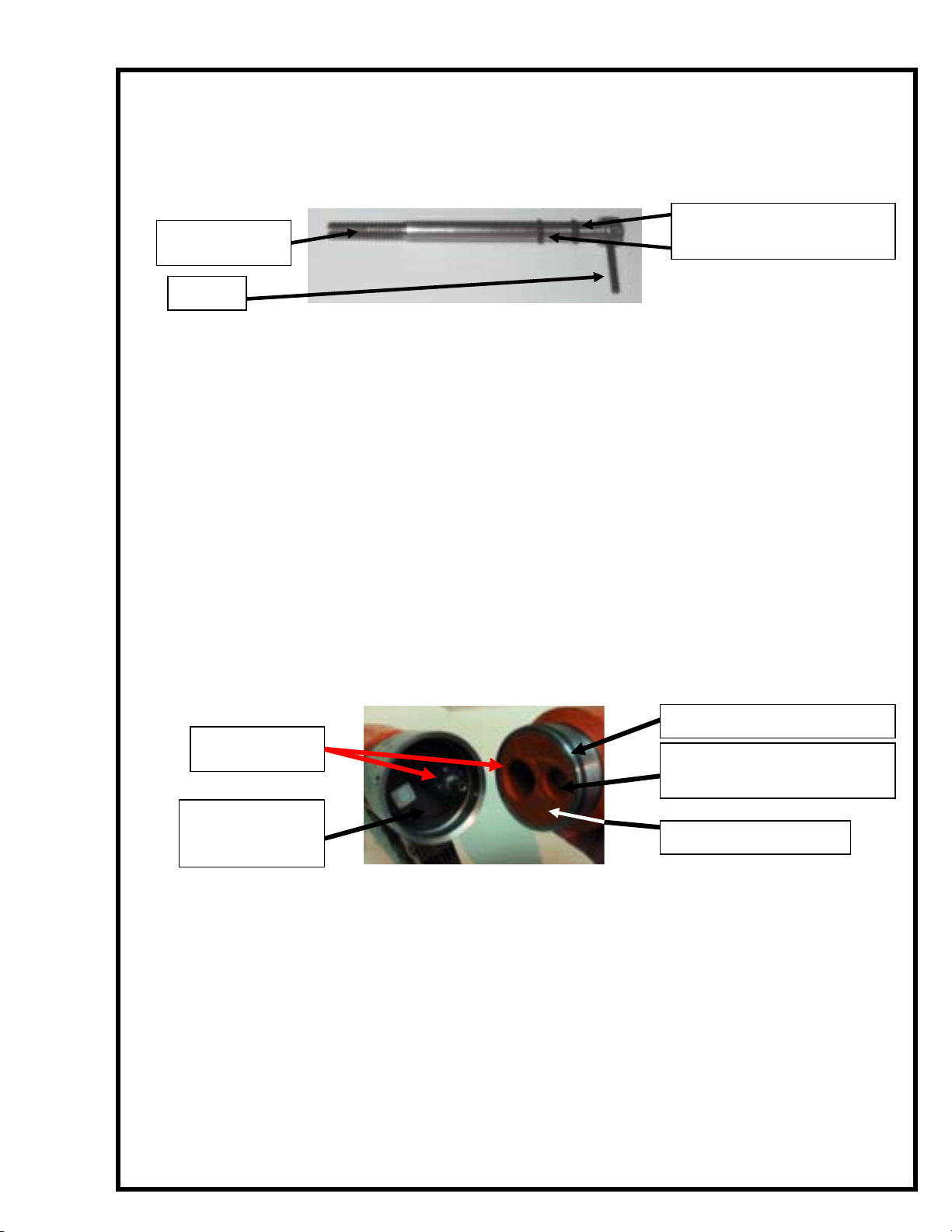
Special attention should be employed to the sealing surface on the inside of
the Yokes Junction Tube, and the O-Ring seal on the Battery Pack and
Switch Plunger. These are the primary seal of the system, and must be free
of rust, dirt, and any foreign matter. A supply of O-Rings (42mm x 48mm x
3mm –ID/OD/Dia.) are included in the WC-9UW Kit, and should be changed
frequently. The fit of the Sealing System should be reasonably tight however,
it there is a “loose fit”, report the problem to the distributor or Western
Instruments for instructions on corrective action. Do not operate the unit in
hazardous environments when the Battery Pack in not fully assembled.
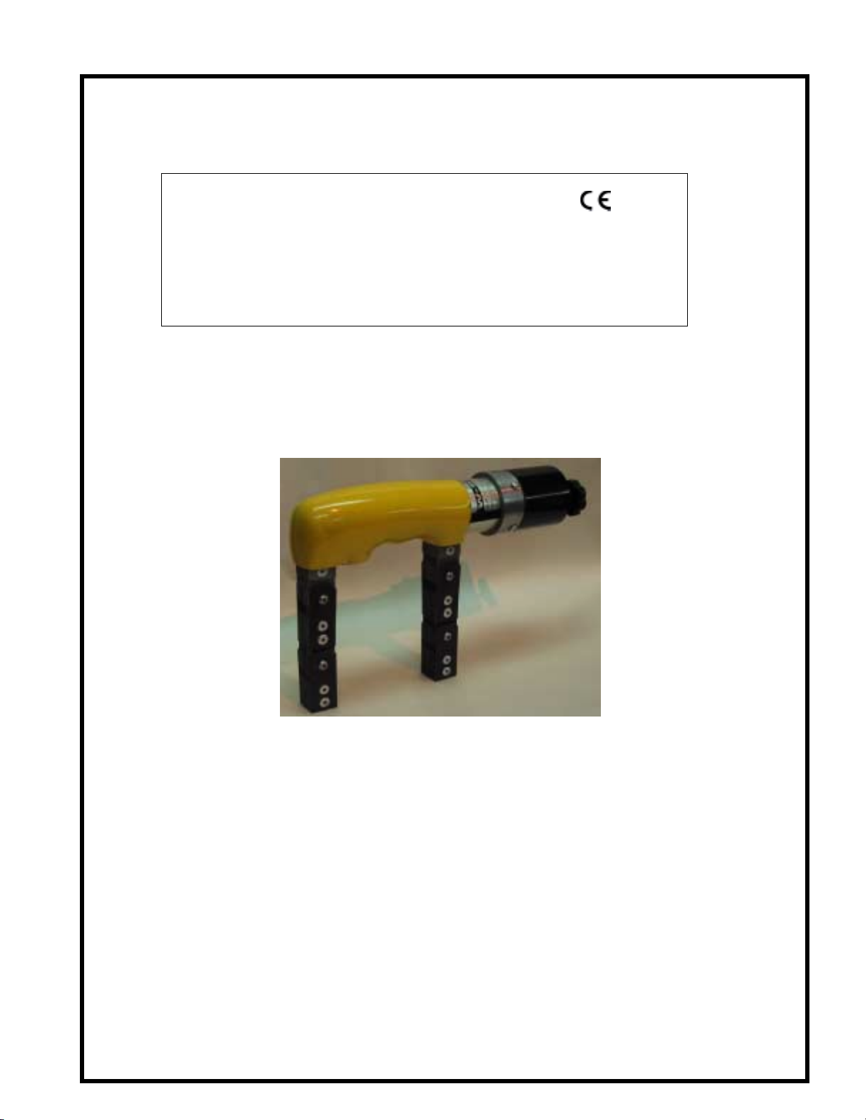
Whether industrial specifications are being observed or not, the Yoke should
be tested periodically, using certified Pull Test Bar(s) such as the W-Series
W-PT, to ensure it continues to lift the specified amount of weight. If the
unit fails such a test, first inspect the Pole Pieces to ensure they fully contact
the test weight. If the unit continues to fail, contact the Distributor or Western
Instruments for instructions on corrective action.
7. Warranty – Western Instruments warrants this product, against defects in
materials and workmanship for a period of 3 months from receipt by the end
user. If Western Instruments receives notice of such defects during the
warranty period, Western Instruments will either, at it’s option, repair, replace,
or condemn products that prove to be defective. Due to the nature of the
Underwater operational environment for this product, excessive corrosion is
considered misuse. Consumable items, such as Batteries, are warranted for
30 days from the date of shipment.
Any warranty is void if the unit has been modified in any way, or if it has been
repaired by an unauthorized agency. The end user agrees that any
equipment’s disposition, when returned for warranty work, is at the full
discretion of Western Instruments as to whether a claim is under warranty or
due to misuse. Western Instruments warranty shall overlook normal wear,
however does not include operation outside the general specification outlined
in these instructions. All warranty work is FOB Western Instruments, and any
returned units shall include a written description, by the end user, of the
fault.
Western Instruments makes no other warranty, either expressed or implied,
with respect to this product. Western Instruments specifically disclaims any
liability arising from the use of this equipment. For the correct use of the
product, refer to the Operating Instructions, furthermore we recommend
instructional training to CGSB, ASNT, or other regulatory authority
qualifications.

WC-9UW 8
Western Instruments highly recommends the end user exercise all
possible safety precautions, including use of protective equipment,
while operating this or other industrial equipment.
Specifications:
Model: WC-9UW
Battery Voltage: 13.2VDC
Current Draw: 0.5 Amps @ 13.2 Volts DC
Charger Voltage: 115VAC or 230VAC Adapter (K)
Capacity: 50 Pounds (22.7 Kg)
Pole Spacing: 0 – 11” (0 – 280mm)
Weight: 7.8 Pounds (3.5 Kg)
WesternInstrumentsInc.
WesternInstrumentsInc.WesternInstrumentsInc.
WesternInstrumentsInc.
Phone: (780) 459-6720
Fax: (780) 459-7837
E-mail: info@westerninstruments.com
Web: www.westerninstruments.com
Table of contents
Other Western Instruments Test Equipment manuals
Popular Test Equipment manuals by other brands

Supco
Supco CPH100 operating instructions

Matatakitoyo Torque Tools
Matatakitoyo Torque Tools MTS-3002 Operation manual

Cellebrite
Cellebrite UNIVERSAL FORENSIC EXTRACTION DEVICE... user manual

T&R
T&R 200A-3PH Operating and maintenance manual

NEC
NEC SpectraView Profiler 5 user manual

Tripp Lite
Tripp Lite T015-POE owner's manual

Vents
Vents VUTR 200 V2 EC A17 user manual

EGAmaster
EGAmaster Egatronik 51249 operating instructions

Wurtec
Wurtec 30-10001669 instructions

Tektronix
Tektronix TDS 500D series Supplement manual

ELECTROMATIC
ELECTROMATIC Check Line DT-311A operating instructions

System Sensor
System Sensor Zonecheck Installation and maintenance instructions