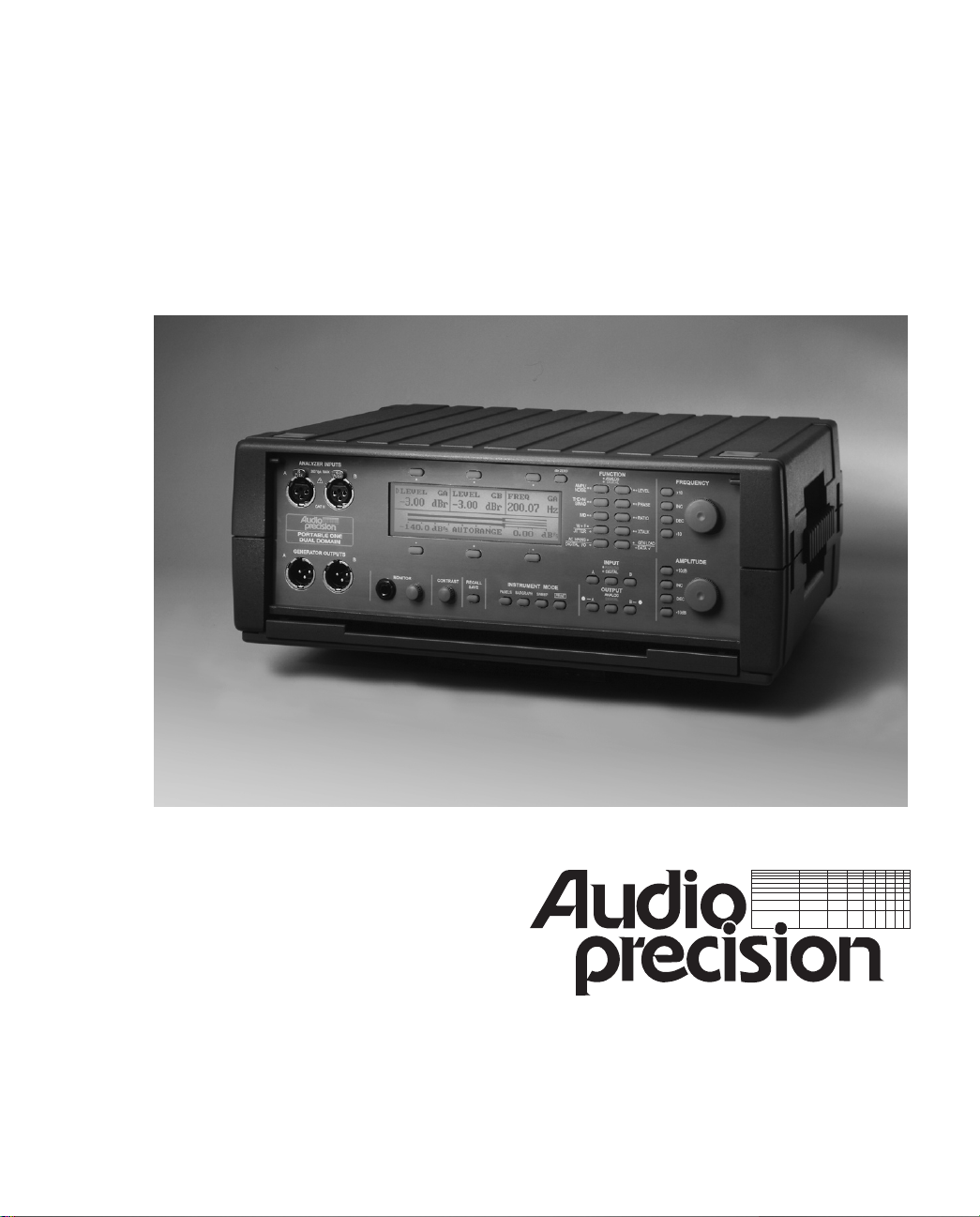
Audio Precision Portable One Dual Domain User manual

Portable One Dual Domain
User's Manual
Advanced Test Equipment Rentals
www.atecorp.com 800-404-ATEC (2832)
®
E
s
t
a
b
l
i
s
h
e
d
1
9
8
1
Portable One Dual Domain
User’s Manual
Version 1.2
January 23, 1998

Audio Precision Portable One Dual Domain User’s Manual
Version 1.2, January 1998
Copyright © 1998 Audio Precision, Inc. All rights reserved. No part of this
document may be reproduced or transmitted in any form or by any means,
electronic or mechanical, including photocopying, recording, or by any information
storage and retrieval system, without permission in writing from the publisher.
Audio Precision®, System One®, System One + DSP, System Two,
FASTTEST®, APWIN, Portable One®, and Dual Domain® are trademarks or
registered trademarks of Audio Precision, Inc.
This mark signifies that the product conforms to all applicable
requirements of the European Community. A Declaration of
Conformance is included with the user information that describes the
specifications used to demonstrate conformity.
Published by:
Printed in the United States of America
Audio Precision Part # 8211.0024
Audio Precision, Inc.
PO Box 2209
Beaverton, Oregon 97075-2209
U.S. Toll Free: 1-800-231-7350
Tel: (503) 627-0832 Fax: (503) 641-8906
email: [email protected]
Web: www.audioprecision.com

Introduction to this Manual
This is the primary operator’s manual for the Portable One Dual
Domain. It describes all aspects of the instrument’s features and
functionality.
Audio Precision makes every effort to make the instrument simple and
easy to use. However, some background in audio testing may be
necessary in order to understand all aspects of this manual and the
functionality of the Portable One Dual Domain.
The first chapter is a basic introduction to the instrument and this
manual. It includes a section on symbols which are used for your
safety and the table of contents.
The second chapter explains how to set up the instrument. This is the
place to start if you want to get up and running right away.
The third chapter discusses the external connections to the Portable
One Dual Domain. You will want to read this section for instructions
on connecting to the device-under-test, printers, oscilloscopes, house
sync sources, or other equipment.
The fourth chapter is about operating the instrument. It describes the
buttons and knobs, the information shown on the display, and how to
control every aspect of the instrument.
The fifth chapter is about applying the Portable One Dual Domain to
specific real-world situations. If you are involved in any of the
situations listed in this chapter, you may find some useful hints.
The sixth chapter contains technical diagrams of the internals of the
instrument. While not necessary to operate the Portable One Dual
Domain, these diagrams may allow advanced users to apply it more
intelligently and understand its limitations.
Appendixes include a quick reference to available units, instructions on
changing the option filters, audible monitor source and AC mains
voltage, instructions for running the instrument’s self test, and complete
instrument specifications.
&This symbol is
used throughout this
manual to direct you
to more information
on related topics.
Introduction to this Manual
Portable One Dual Domain User's Manual Pg i
Safety Symbols
The following symbols may be marked on the panels or covers of
equipment or modules, and are used in this manual:
WARNING! - This symbol alerts you to a potentially hazardous
condition, such as the presence of dangerous voltage that could pose a
risk of electrical shock. Refer to the accompanying Warning Label or
Tag, and exercise extreme caution.
ATTENTION! - This symbol alerts you to important operating
considerations or a potential operating condition that could damage
equipment. If you see this marked on equipment, consult the User’s
Manual or Operator’s Manual for precautionary instructions.
FUNCTIONAL EARTH TERMINAL - This symbol marks a terminal
that is electrically connected to a reference point of a measuring circuit
or output and is intended to be earthed for any functional purpose
other than safety.
PROTECTIVE EARTH TERMINAL - This symbol marks a terminal that
is bonded to conductive parts of the instrument. Confirm that this
terminal is connected to an external protective earthing system.
Safety Symbols
Pg ii Portable One Dual Domain User's Manual

Contents
Introducing the Portable One Dual Domain . . . . . . . . . . . . . . . . 1-1
Getting Started . . . . . . . . . . . . . . . . . . . . . . . . . . . . . . . 2-1
Front Cover and Tilt Bail . . . . . . . . . . . . . . . . . . . . . . . . . . . . . 2-1
Connecting Mains Supply Voltage . . . . . . . . . . . . . . . . . . . . . . . . 2-3
Safety Information . . . . . . . . . . . . . . . . . . . . . . . . . . . . . . . . 2-4
Front Panel Overview . . . . . . . . . . . . . . . . . . . . . . . . . . . . . . . 2-6
Rear Panel Overview . . . . . . . . . . . . . . . . . . . . . . . . . . . . . . . . 2-8
Options Label . . . . . . . . . . . . . . . . . . . . . . . . . . . . . . . . . . . . 2-10
Typical Connections . . . . . . . . . . . . . . . . . . . . . . . . . . . . . . . . 2-11
External Connections . . . . . . . . . . . . . . . . . . . . . . . . . . . . 3-1
Concepts and Terminology . . . . . . . . . . . . . . . . . . . . . . . . . . . . 3-1
Analog vs. Digital . . . . . . . . . . . . . . . . . . . . . . . . . . . . . . . 3-1
Balanced vs. Unbalanced . . . . . . . . . . . . . . . . . . . . . . . . . . . 3-2
Analog Inputs and Outputs . . . . . . . . . . . . . . . . . . . . . . . . . . . . 3-3
Digital Inputs and Outputs . . . . . . . . . . . . . . . . . . . . . . . . . . . . 3-6
Reference Input . . . . . . . . . . . . . . . . . . . . . . . . . . . . . . . . . . 3-8
Trigger Outputs . . . . . . . . . . . . . . . . . . . . . . . . . . . . . . . . . . 3-9
Monitor Outputs . . . . . . . . . . . . . . . . . . . . . . . . . . . . . . . . . . 3-11
Printer Port . . . . . . . . . . . . . . . . . . . . . . . . . . . . . . . . . . . . 3-12
GPIB Interface . . . . . . . . . . . . . . . . . . . . . . . . . . . . . . . . . . . 3-13
Operation . . . . . . . . . . . . . . . . . . . . . . . . . . . . . . . . . . . 4-1
Overview . . . . . . . . . . . . . . . . . . . . . . . . . . . . . . . . . . . . . . 4-1
CONTRAST Knob . . . . . . . . . . . . . . . . . . . . . . . . . . . . . . . . 4-1
INSTRUMENT MODE Keys – Navigating the Panels . . . . . . . . . . . . . . 4-1
RECALL/SAVE Key . . . . . . . . . . . . . . . . . . . . . . . . . . . . . . . . 4-5
Soft Keys . . . . . . . . . . . . . . . . . . . . . . . . . . . . . . . . . . . . 4-5
FUNCTION Keys . . . . . . . . . . . . . . . . . . . . . . . . . . . . . . . . . 4-5
INPUT Keys . . . . . . . . . . . . . . . . . . . . . . . . . . . . . . . . . . . 4-6
OUTPUT Keys . . . . . . . . . . . . . . . . . . . . . . . . . . . . . . . . . . 4-6
FREQUENCY Controls . . . . . . . . . . . . . . . . . . . . . . . . . . . . . . 4-6
AMPLITUDE Controls . . . . . . . . . . . . . . . . . . . . . . . . . . . . . . 4-7
Contents
Portable One Dual Domain User's Manual Pg iii

dBr Zero Key . . . . . . . . . . . . . . . . . . . . . . . . . . . . . . . . . . 4-8
MONITOR Operation . . . . . . . . . . . . . . . . . . . . . . . . . . . . . . 4-8
Setup Panel . . . . . . . . . . . . . . . . . . . . . . . . . . . . . . . . . . . 4-8
Screen Saver . . . . . . . . . . . . . . . . . . . . . . . . . . . . . . . . . 4-10
Controlling the Generators . . . . . . . . . . . . . . . . . . . . . . . . . . . 4-11
Generators Overview . . . . . . . . . . . . . . . . . . . . . . . . . . . . 4-11
Generator Control Modes . . . . . . . . . . . . . . . . . . . . . . . . . . 4-12
Analog Generator Mode (A:GEN) . . . . . . . . . . . . . . . . . . . . . . 4-14
Digital Audio Generator Mode (D:GEN) . . . . . . . . . . . . . . . . . . . 4-15
Digital Sample Rate Generator Mode (D:RATE) . . . . . . . . . . . . . . . 4-16
Digital Jitter Generator Mode (D:JIT) . . . . . . . . . . . . . . . . . . . . 4-17
Analog Generator Loading . . . . . . . . . . . . . . . . . . . . . . . . . 4-18
Digital Status Bits . . . . . . . . . . . . . . . . . . . . . . . . . . . . . . . 4-20
Controlling the Analyzer . . . . . . . . . . . . . . . . . . . . . . . . . . . . . 4-22
Analyzer Overview . . . . . . . . . . . . . . . . . . . . . . . . . . . . . . 4-22
Analog and Digital Modes . . . . . . . . . . . . . . . . . . . . . . . . . . 4-24
Input Selection Buttons . . . . . . . . . . . . . . . . . . . . . . . . . . . 4-25
FUNCTION Keys . . . . . . . . . . . . . . . . . . . . . . . . . . . . . . . . 4-26
FUNCTION Descriptions . . . . . . . . . . . . . . . . . . . . . . . . . . . . 4-26
Amplitude . . . . . . . . . . . . . . . . . . . . . . . . . . . . . . . . . . . 4-28
Noise . . . . . . . . . . . . . . . . . . . . . . . . . . . . . . . . . . . . . . 4-31
Level . . . . . . . . . . . . . . . . . . . . . . . . . . . . . . . . . . . . . . 4-33
THD+N (Total Harmonic Distortion plus Noise) . . . . . . . . . . . . . . 4-35
Special Section: Understanding THD+N . . . . . . . . . . . . . . . . . . 4-39
What Signal is Dominant? . . . . . . . . . . . . . . . . . . . . . . . . 4-41
Selecting Bandwidth . . . . . . . . . . . . . . . . . . . . . . . . . . . 4-41
Changes with Frequency . . . . . . . . . . . . . . . . . . . . . . . . 4-44
Changes with Amplitude . . . . . . . . . . . . . . . . . . . . . . . . 4-45
THD+N at 100% (or 0 dB) . . . . . . . . . . . . . . . . . . . . . . . . 4-46
Isolating Sources of THD+N . . . . . . . . . . . . . . . . . . . . . . . 4-47
SINAD . . . . . . . . . . . . . . . . . . . . . . . . . . . . . . . . . . . . . 4-48
Phase . . . . . . . . . . . . . . . . . . . . . . . . . . . . . . . . . . . . . 4-50
IMD . . . . . . . . . . . . . . . . . . . . . . . . . . . . . . . . . . . . . . . 4-53
Ratio . . . . . . . . . . . . . . . . . . . . . . . . . . . . . . . . . . . . . . 4-55
W+F (Wow and Flutter) . . . . . . . . . . . . . . . . . . . . . . . . . . . 4-58
XTALK (Crosstalk) . . . . . . . . . . . . . . . . . . . . . . . . . . . . . . . 4-61
AC Mains (Power Line Monitor) . . . . . . . . . . . . . . . . . . . . . . . 4-63
Gen Load . . . . . . . . . . . . . . . . . . . . . . . . . . . . . . . . . . . 4-65
Jitter . . . . . . . . . . . . . . . . . . . . . . . . . . . . . . . . . . . . . . 4-67
Digital I/O . . . . . . . . . . . . . . . . . . . . . . . . . . . . . . . . . . . 4-70
Data Check . . . . . . . . . . . . . . . . . . . . . . . . . . . . . . . . . . 4-73
Status Bits . . . . . . . . . . . . . . . . . . . . . . . . . . . . . . . . . . . 4-76
Contents
Pg iv Portable One Dual Domain User's Manual

Bargraphs . . . . . . . . . . . . . . . . . . . . . . . . . . . . . . . . . . . 4-79
Sweeps . . . . . . . . . . . . . . . . . . . . . . . . . . . . . . . . . . . . . 4-81
Continuous Sweeps . . . . . . . . . . . . . . . . . . . . . . . . . . . . . . 4-84
External Sweeps . . . . . . . . . . . . . . . . . . . . . . . . . . . . . . . . 4-85
Printing . . . . . . . . . . . . . . . . . . . . . . . . . . . . . . . . . . . . . 4-85
Saving and Recalling Setups . . . . . . . . . . . . . . . . . . . . . . . . . 4-90
Printing Saved Data . . . . . . . . . . . . . . . . . . . . . . . . . . . . . . 4-92
Units . . . . . . . . . . . . . . . . . . . . . . . . . . . . . . . . . . . . . . . . 4-93
Analog amplitude units . . . . . . . . . . . . . . . . . . . . . . . . . . . . 4-93
Special Section: Is it dBm or dBu? . . . . . . . . . . . . . . . . . . . . . . 4-95
Analog power units . . . . . . . . . . . . . . . . . . . . . . . . . . . . . . 4-96
Time and Frequency units . . . . . . . . . . . . . . . . . . . . . . . . . . 4-97
Phase units . . . . . . . . . . . . . . . . . . . . . . . . . . . . . . . . . . . 4-98
Digital time units . . . . . . . . . . . . . . . . . . . . . . . . . . . . . . . 4-99
Digital amplitude units . . . . . . . . . . . . . . . . . . . . . . . . . . . 4-100
Applications . . . . . . . . . . . . . . . . . . . . . . . . . . . . . . . . . 5-1
Frequency Response of
Amplifiers, Mixing Consoles, Etc. . . . . . . . . . . . . . . . . . . . . . . . . . 5-1
Audio Transmission Link Testing . . . . . . . . . . . . . . . . . . . . . . . . . 5-1
Analog Tape Recorder Alignment
and Performance Verification . . . . . . . . . . . . . . . . . . . . . . . . . . 5-2
Reproduce Mode . . . . . . . . . . . . . . . . . . . . . . . . . . . . . . . 5-2
Record-Reproduce Mode . . . . . . . . . . . . . . . . . . . . . . . . . . . 5-3
Compact Disc Players . . . . . . . . . . . . . . . . . . . . . . . . . . . . . . . 5-5
Detailed Technical Diagrams . . . . . . . . . . . . . . . . . . . . . . . . 6-1
Block Diagrams . . . . . . . . . . . . . . . . . . . . . . . . . . . . . . . . . . . 6-1
Analog Section . . . . . . . . . . . . . . . . . . . . . . . . . . . . . . . . . 6-1
Digital Section . . . . . . . . . . . . . . . . . . . . . . . . . . . . . . . . . 6-3
Analog Generator Output Circuit . . . . . . . . . . . . . . . . . . . . . . . . 6-6
Analog Analyzer Input Circuit . . . . . . . . . . . . . . . . . . . . . . . . . . 6-8
Cable Diagrams . . . . . . . . . . . . . . . . . . . . . . . . . . . . . . . . . . . 6-10
Balanced Connections . . . . . . . . . . . . . . . . . . . . . . . . . . . . 6-10
Unbalanced Connections . . . . . . . . . . . . . . . . . . . . . . . . . . . 6-11
Unbalanced Stereo Connections . . . . . . . . . . . . . . . . . . . . . . . 6-13
Appendix A - Units Quick Reference . . . . . . . . . . . . . . . . . . . . 7-1
Contents
Portable One Dual Domain User's Manual Pg v

Appendix B - Option Filter Installation . . . . . . . . . . . . . . . . . . . 8-1
Appendix C - Monitor Source Selection . . . . . . . . . . . . . . . . . . . 9-1
Appendix D - Line Voltage and Fuse Selection . . . . . . . . . . . . . . 10-1
Checking the Selected Line Voltage . . . . . . . . . . . . . . . . . . . . . . 10-1
Changing the Line Voltage Selection . . . . . . . . . . . . . . . . . . . . . . 10-2
Checking the Fuse Block Orientation . . . . . . . . . . . . . . . . . . . . . . 10-3
Changing the Fuse Block Orientation . . . . . . . . . . . . . . . . . . . . . 10-4
Checking the Fuses . . . . . . . . . . . . . . . . . . . . . . . . . . . . . . . . 10-5
Appendix E - Filter Shapes . . . . . . . . . . . . . . . . . . . . . . . . . 11-1
Appendix F - Self Test . . . . . . . . . . . . . . . . . . . . . . . . . . . 12-1
Appendix G - Specifications . . . . . . . . . . . . . . . . . . . . . . . . 13-1
Index . . . . . . . . . . . . . . . . . . . . . . . . . . . . . . . . . . . . 14-1
Contents
Pg vi Portable One Dual Domain User's Manual

Introducing the Portable One Dual Domain
The Audio Precision Portable One Dual Domain is a comprehensive
two-channel audio test instrument. It is capable of analog, digital, and
cross-domain (analog-to-digital or digital-to-analog) measurements. It
features the following measurement functions:
In both analog and digital domains:
.Level (two channels simultaneously)
.Noise or signal-to-noise ratio (wideband, weighted, or selective)
.THD+N (total harmonic distortion plus noise)
.Interchannel phase
.SMPTE/DIN intermodulation distortion (optional)
.Real-time two-channel amplitude ratio (interchannel balance or
device gain/loss)
.Real-time frequency-selective crosstalk
Figure 1-1 Portable One Dual Domain
1Introduction
Introducing the Portable One Dual Domain
Portable One Dual Domain User's Manual Pg 1-1

In the analog domain:
.Wow and Flutter
.SINAD (ratio of {signal + noise + distortion} to {noise +
distortion})
.Phase shift through a device
.Loading (AC resistance of the input of a device connected to the
generator output)
.AC mains check (voltage, frequency, and distortion of the AC
power line)
In the digital domain:
.Jitter amplitude and frequency
.Digital data activity and integrity
.Sample rate, amplitude, and delay of digital carrier signal
.Status Bits
The Portable One Dual Domain can sweep most of these
measurements across a user-specified frequency or amplitude range
and display a graph of the results. The graph top and bottom values
may be set by the user, even after a sweep, with the data dynamically
re-scaling. After sweeping, a cursor may be used to provide numeric
readout of any point on the graph.
Printer support is provided, allowing printout of high-resolution graphs,
fast screen dumps, numerical data from sweeps or self-test, and
printout of bargraph displays.
The Portable One Dual Domain is capable of generating low-distortion
sine and square waveforms, plus an intermodulation distortion test
signal (with purchase of intermodulation distortion option).
1Introduction
Introducing the Portable One Dual Domain
Pg 1-2 Portable One Dual Domain User's Manual

Measurements may be displayed in a wide variety of units, including
the following:
.volts
.dBm (with a user-specified impedance reference)
.dBu
.dBV
.dBr (dB relative to a stored measured value)
.dBg (dB relative to the present generator output amplitude)
.watts (with a user-specified impedance reference)
.FFS (Fraction of Full Scale, for digital measurements)
.dBFS (dB below Full Scale, for digital measurements)
.Hz/kHz
.% or dB for relative measurements
The chosen units are remembered for each measurement function, so
when you return to that function the units will be automatically
displayed.
Several band-limiting and noise-weighting filters are provided. In the
analog domain, the following are available:
.Standard 22 Hz-22 kHz audio bandpass
.30 kHz and 80 kHz lowpass
.400 Hz highpass
.Tunable 1/3 octave bandpass
.A-weighting (IEC-A)
.CCIR weighting
.Sockets for two optional filters, selectable from a wide variety
In the digital domain, the following filters are available:
.22 Hz and 400 Hz highpass
.15 kHz, 20 kHz, 22 kHz, and Sample Rate/2 lowpass
.A-weighting (ANSI/IEC-A)
.CCIR weighting (two types)
.Tunable 1/13 octave bandpass
1Introduction
Introducing the Portable One Dual Domain
Portable One Dual Domain User's Manual Pg 1-3

The selected filter for each measurement function is remembered, so
that next time you use that function the same filter will be selected.
Signals within the audible range can be monitored using the built-in
loudspeaker or with user-supplied headphones. An external volume
control is provided.
Up to 30 complete panel setups can be stored in internal memory so
that common test setups can be easily recalled. This memory persists
even when the unit is unplugged. In addition, test setups can be stored
with a set of data, so that field test results can be saved for later
analysis or printing.
All measurements, settings, and graphs are displayed on a sharp, clear,
backlighted liquid crystal display.
The Portable One Dual Domain is the latest addition to Audio
Precision’s Portable family, which also includes the Portable One Plus
Access and the ATS-1. All of the Portable units feature similar analog
capabilities and the same easy-to-use interface in a convenient,
portable package.
The Portable One Dual Domain can be purchased with or without the
‘P1-IMD’ option, which allows generation and analysis of
Intermodulation Distortion in both digital and analog domains.
The Portable One Dual Domain may also be purchased with the
‘EURZ’ option, which replaces the 150 Ωgenerator output impedance
with 200 Ω, which is more common in European broadcast.
Another option is ‘P1DD-488’, which provides GPIB capabilities for
connection to computer-controlled automation systems.
Other options include a soft carrying case and optional filters for
specific band-limiting or weighting applications.
Any installed options are listed on the Options Label on the rear panel.
&For more
information on the
Options Label, see
page 2-10.
1Introduction
Introducing the Portable One Dual Domain
Pg 1-4 Portable One Dual Domain User's Manual

1Introduction
Introducing the Portable One Dual Domain
Portable One Dual Domain User's Manual Pg 1-5

Getting Started
Front Cover and Tilt Bail
The two square blue buttons on top of the instrument are releases for
the protective front cover. Press these buttons (as shown in the
following figure), and then pivot the cover down to a horizontal
position and slide it into the storage slot below the front panel .
Notice that on the inside of the cover are simplified operation
instructions for use as a quick reminder of common feature usage.
Cover Release
Buttons
Figure 2-1 Cover Release Buttons
2Getting Started
Front Cover and Tilt Bail Getting Started
Portable One Dual Domain User's Manual Pg 2-1
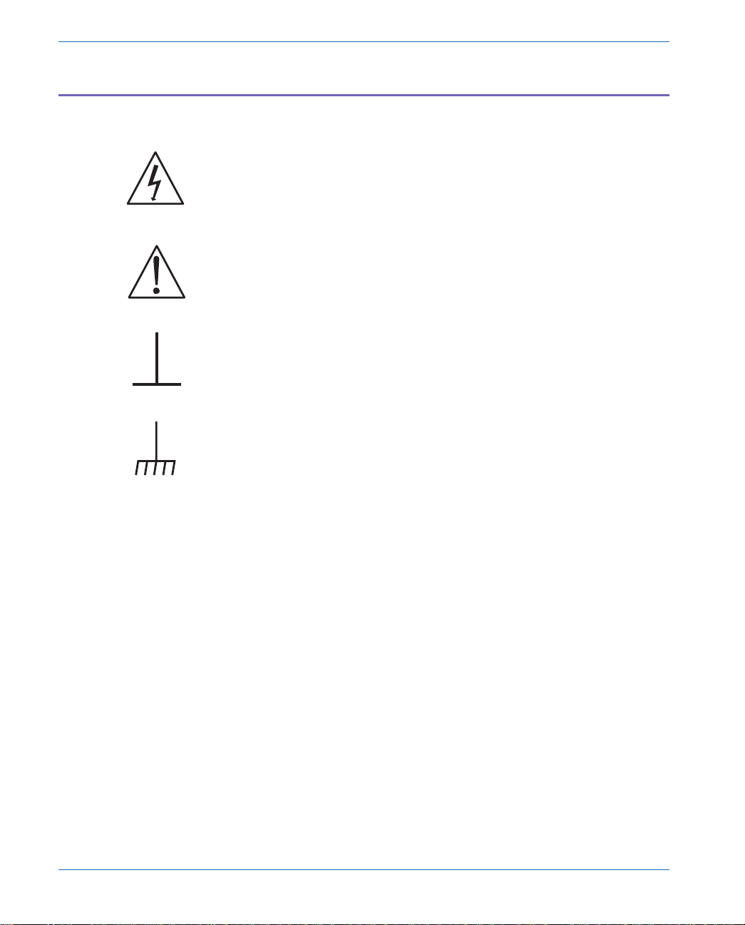
The tilt bail is used to elevate the front of the instrument for more
comfortable viewing. It is located on the bottom of the instrument, near
the front. Normally it will be latched into its storage position. To use
it, pivot it out toward the front panel and rest the instrument on it, as
shown in the following figure:
Tilt Bail
Figure 2-2 Tilt Bail
2Setting Up
Getting Started Front Cover and Tilt Bail
Pg 2-2 Portable One Dual Domain User's Manual
Connecting Mains Supply Voltage
Before plugging the unit in for the first time, it is a good idea to verify
that the power supply line voltage selection is correct. The units are
configured at the factory for the expected voltage at their intended
destination, so usually the voltage will be correct unless the unit has
been transported into another area.
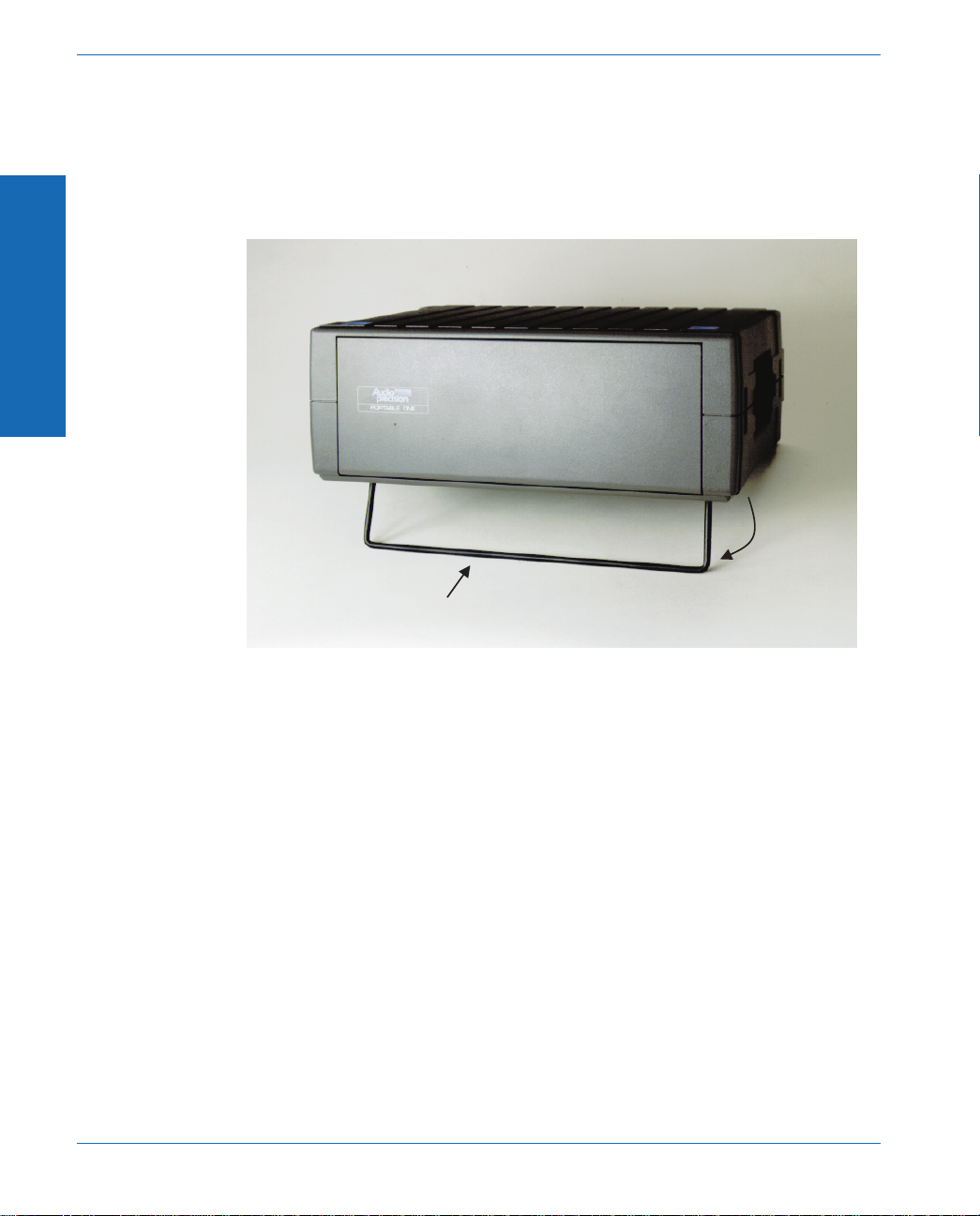
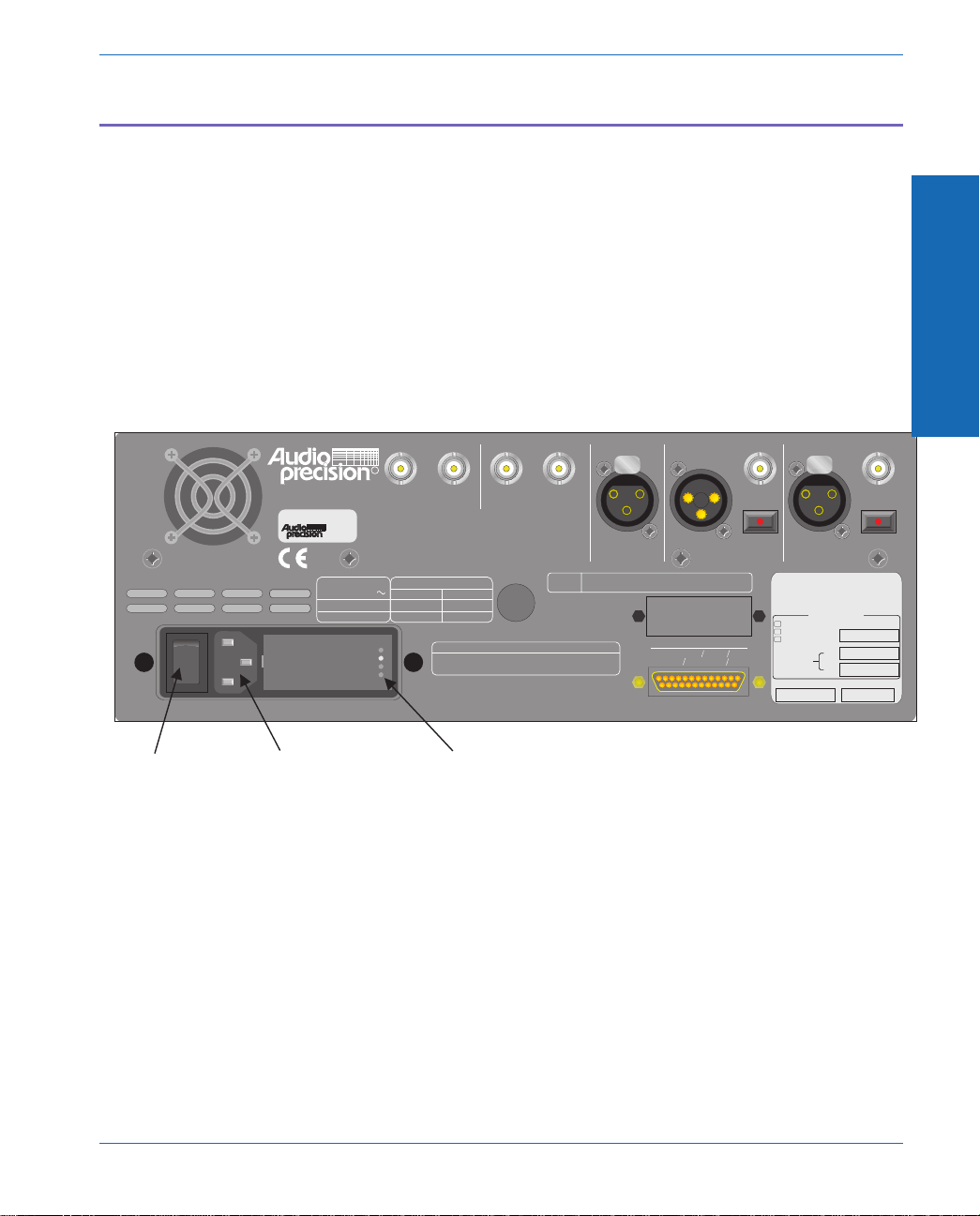
The supply voltage indicator is located on the rear panel of the
instrument next to the power plug. A small white plastic indicator tip
identifies the line voltage setting as 100V, 120V, 230V, or 240 V.
The following diagram shows the location of the voltage indicators:
In one of the holes should be a small white plastic indicator tip
showing which line voltage is currently selected. If the selected voltage
is not the same as the line voltage in your area, see Appendix E for
instructions on changing the line voltage selection.
Once the line voltage selection is correct, connect the line cord from
the power outlet to the power cord connector and move the power
switch to the ‘On’ position (marked ‘1’).
I
O
Date of manufacture Code
Audio Measurement System
PORTABLE ONE
DUAL DOMAIN
Aux 2:
Aux 1:
Opt'l Filters:
Installed Options:
Special
EGZ Euro. Impedances
P1P-488 GPIB Inter.
P1-IMD Intermod. Distortion
LINE VOLTAGE
INDICATOR HOLES
FUSE REPLACEMENT DATA
230/240 VAC 250mA T/SB 250V
100/120 VAC 500mA T/SB 250V
SUPPLY VOLTAGE FUSE
MAXIMUM POWER: 60 VA
FREQUENCY: 50/60 Hz.
100/120/230/240 VAC
SUPPLY VOLTAGE:
INPUT ANALYZER
BAL
BAL
UNBAL UNBAL
5Vpp MAX
5Vpp MAX
OPTICAL
INPUT
REFERENCE DIGITAL OUTPUT
Manufactured in Beaverton, Oregon, USA
PARALLEL PRINTER
IEEE-488 INTERFACE
5,247,458; 5,420,516; 5,336,989. Other patent applications pending.
4,614,914; 4,563,652; 4,631,522; 5,089,981; 5,136,267; 5,265,201;
This product is protected by one or more of the following patents:
INSTRUMENT RESET
To restore factory default instrument settings,
hold dBr button and turn on mains power switch.
RL1, PP0, DC1, DT1, C0, E1
SH1, AH1, T6, TE0, L4, LE0, SR1,
PORTABLE ONE
TRIGGER SIGNALS
ANALOG DIGITAL
GPIB
ADDRESS
DIGITAL INPUT
OPTICAL
To set instrument GPIB address, use utility menu
under PANELS selection on front panel.
MONITORS
R
100 V
120 V
230 V
240 V
POWER CORD
CONNECTOR
POWER
SWITCH
Figure 2-3 Location of Voltage Indicators
2Getting Started
Connecting Mains Supply Voltage Getting Started
Portable One Dual Domain User's Manual Pg 2-3

Safety Information
Do NOT service or repair this product unless properly qualified.
Servicing should be performed only by a qualified technician or an
authorized Audio Precision distributor.
Do NOT defeat the safety ground connection. This product is
designed to operate only from a 50/60 Hz AC power source (250 Vrms
maximum) with an approved three-conductor power cord and safety
grounding. Loss of the protective grounding connection can result in
electrical shock hazard from the accessible conductive surfaces of this
product.
For continued fire hazard protection, fuses should be replaced ONLY
with the exact value and type indicated on the rear panel of the
instrument and discussed on page 10-5 of this manual. The AC
voltage selector also must be set to the same voltage as the nominal
power source voltage (100, 120, 230, or 240 Vrms) with the
appropriate fuses. Different fuses are required depending on the line
voltage.
The International Electrotechnical Commission (IEC 1010-1) requires
that measuring circuit terminals used for voltage or current
measurement be marked to indicate their Installation Category. The
Installation Category is defined by IEC 664 and is based on the
amplitude of transient or impulse voltage that can be expected from
the AC power distribution network. This product is classified as
INSTALLATION CATEGORY II, abbreviated “CAT II” on the
instrument front panel.
Do NOT substitute parts or make any modifications without the written
approval of Audio Precision. Doing so may create safety hazards.
This product contains lithium batteries. Dispose only in accordance
with applicable regulations.
This product is for indoor use - pollution degree 2.
2Setting Up
Getting Started Safety Information
Pg 2-4 Portable One Dual Domain User's Manual

Safety Symbols
The following symbols may be marked on the panels or covers of
equipment or modules, and are used in this manual:
WARNING! - This symbol alerts you to a potentially hazardous
condition, such as the presence of dangerous voltage that could pose a
risk of electrical shock. Refer to the accompanying Warning Label or
Tag, and exercise extreme caution.
ATTENTION! - This symbol alerts you to important operating
considerations or a potential operating condition that could damage
equipment. If you see this marked on equipment, consult the User’s
Manual or Operator’s Manual for precautionary instructions.
FUNCTIONAL EARTH TERMINAL - This symbol marks a terminal
that is electrically connected to a reference point of a measuring circuit
or output and is intended to be earthed for any functional purpose
other than safety.
PROTECTIVE EARTH TERMINAL - This symbol marks a terminal that
is bonded to conductive parts of the instrument. Confirm that this
terminal is connected to an external protective earthing system.
2Getting Started
Safety Information Getting Started
Portable One Dual Domain User's Manual Pg 2-5

Front Panel Overview
.SOFT KEYS - These six keys have a variety of purposes
depending on what is displayed on the screen. In most cases,
the upper buttons change display units and the lower buttons
change parameters shown just above the button on the display.
.LCD DISPLAY - This is where all readings, graphs, and
operating parameters are displayed. It also shows the current
functions of the lower soft keys. The display contrast is
controlled by the CONTRAST control. If no buttons are pressed
for two hours, the ‘screen saver’ will be invoked, and the display
will darken to preserve the useful lifetime of the display.
Touching any key will turn it on again.
.dBr KEY - This key is used to set the dBr reference for
measurement to the current measured value. When saving and
recalling setups, it provides some additional soft key functions.
.FUNCTION KEYS - These keys select the measurement to be
performed by the analyzer. The exact function selected will
depend on the analyzer domain (analog or digital), selected by
the center key in the INPUT CONTROL KEYS group. Small
colored dots indicate which measurements are available in
which domain. The legend to these dots is shown at the top of
ANALOG
DIGITAL
ANALOG
DIGITAL
ANALOG
ANALOG
DIGITAL
DIGITAL
LEVEL
PHASE
AC MAINS
JITTER
PORTABLE ONE
DUAL DOMAIN
BA GENERATOR OUTPUTS
350 Vpk MAX
AB
ANALYZER INPUTS
!
CAT II
FREQUENCY
AMPLITUDE
FREQUENCY
DEC
+10dB
INC
-10dB
-10
INC
10
x
.
.
DEC
DEC
+10dB
INC
-10dB
-10
INC
10
x
.
.
DEC
PRINT
INSTRUMENT MODE
PANELS BARGRAPH SWEEP
MONITOR CONTRAST RECALL
SAVE
FUNCTION
OUTPUT
A
ANALOG
B
AB
INPUT
GEN LOAD
DATA
RATIO
XTALK
DIGITAL I/O
IMD
W+F
AMPL/
NOISE
SINAD
THD+N/
dBr ZERO
DIGITALDIGITAL
ANALOG
ANALOG
DIGITAL
DIGITAL
SOFT KEYS dBr KEY FUNCTION
KEYS FREQUENCY
CONTROLS
AMPLITUDE
CONTROLS
INPUT
CONTROL
KEYS
OUTPUT
CONTROL
KEYS
INSTRUMENT
MODE KEYS
RECALL/SAVE
KEY
MONITOR AND
CONTRAST
CONTROLS
ANALOG
INPUTS
ANALOG
OUTPUTS
LCD DISPLAY
ANALOG
DIGITAL
ANALOG
DIGITAL
Figure 2-4 Front Panel Overview
&Screen saver -
page 4-10.
&dBr and other
units - page 4-93.
&Saving and
recalling setups -
page 4-90.
&FUNCTION KEYS -
page 4-26.
&CONTRAST
control - page 4-1.
2Setting Up
Getting Started Front Panel Overview
Pg 2-6 Portable One Dual Domain User's Manual
Table of contents
Other Audio Precision Test Equipment manuals

Audio Precision
Audio Precision ATS-2 User manual

Audio Precision
Audio Precision Portable One Plus Access User manual

Audio Precision
Audio Precision AECM206 User manual

Audio Precision
Audio Precision System Two User manual

Audio Precision
Audio Precision 2700 Series User manual

Audio Precision
Audio Precision ATS-1 User manual

Audio Precision
Audio Precision ATS-2 User manual


