Audio Precision 2700 Series User manual
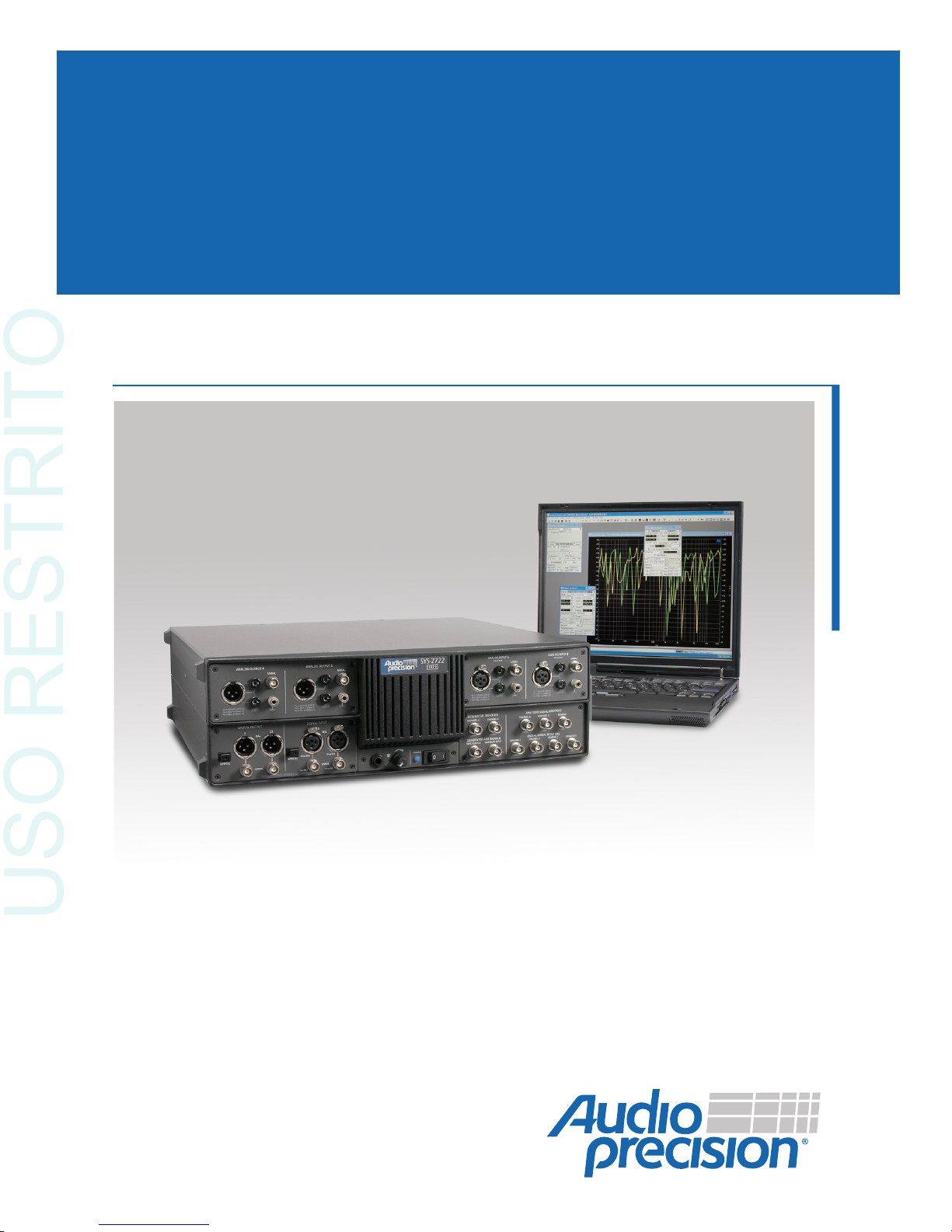
Getting Started with Your 2700 Series Instrument
2700 Series
2 7 2 2 2 7 2 0 2 7 1 2 2 7 0 2
USO RESTRITO

USO RESTRITO

Getting Started with Your
2700 Series Instrument
An Introductory Guide to •SYS-2722 •
and •SYS-2720 •SYS-2712 •SYS-2702 •
with AP2700 3.30 SP1
APIB and GPIB Configurations
USO RESTRITO
All content in this manual is owned by Audio Precision and is
protected by United States and international copyright laws.
Audio Precision allows its customers to make a limited number
of copies of this manual, or portions thereof, solely for use in
connection with the Audio Precision product covered by this
manual. Audio Precision may revoke this permission to make
copies at any time. You may not distribute any copies of the
manual, apart from a transfer of ownership of the Audio
Precision product.
Audio Precision®, System One®, System Two™, System Two
Cascade™, System Two Cascade Plus™, Cascade™,
Cascade Plus™, System One + DSP™, System Two + DSP™,
Dual Domain®, FASTTEST®, APWIN™, ATS™, ATS-2™, 2700
series™ and AP2700™ are trademarks of Audio Precision, Inc.
Windows™ is a trademark of Microsoft Corporation.
Audio Precision instruments equipped with the OPT-2711
Dolby™ Digital Generator are manufactured under license from
Dolby Laboratories. Dolby and the double-D symbol are
trademarks of Dolby Laboratories. Confidential unpublished
works. © 1992–2004 Dolby Laboratories, Inc. All rights
reserved.
Published by:
5750 SW Arctic Drive
Beaverton, Oregon 97005
1-800-231-7350
fax 503-641-8906
503-627-0832
ap.com
Printed in the United States of America
Copyright Ó2003–2013 Audio Precision, Inc.
All rights reserved.
Part Number 8211.0184 Revision 9
This mark signifies that the product conforms to all applicable
requirements of the European Community. A Declaration of
Conformance is included with the user information that
describes the specifications used to demonstrate conformity.
XIII0110110104
USO RESTRITO

Contents
Safety Information ..............................v
Safety Symbols ...............................vi
Disclaimer ..................................vi
Chapter 1
General Information..........................1
The 2700 Series: an Overview........................1
APIB....................................2
GPIB....................................2
2700 Series Capabilities ...........................2
About This Manual..............................3
Other 2700 Series Documentation......................3
2700 Series User’s Manual ........................4
AP Basic Language Manual........................4
AP Basic Extensions Reference for the 2700 Series ...........4
Online Help ................................4
Other Publications.............................4
GPIB Documentation for the 2700 series .................5
Chapter 2
Installation and Setup for APIB ...................7
2700 Series Components ..........................7
Getting Up and Running ...........................8
Installing AP2700 on a PC..........................8
PC System Requirements.........................8
Installing the Software...........................9
Setting Up the Hardware...........................9
Connecting your 2700 Series Instrument
to the Electrical Mains Supply .......................9
Checking the Mains Supply Voltage Configuration ..........10
Opening the Power Entry Module ...................10
Changing the Mains Supply Voltage Configuration ..........11
Getting Started with Your 2700 Series Instrument i
USO RESTRITO

Fuse Information .............................12
Changing the Fusing Arrangement ..................12
Connecting the Instrument to Your PC ...................13
The USB-APIB adapter and cables ...................13
The APIB PCI Express card and cable..................14
The APIB PCI card and cable ......................14
The APIB PCMCIA card and cable....................15
APSI and the Dolby Digital Generator option ..............15
Chapter 3
Hardware Overview .........................17
The SYS-2722 Front Panel.........................17
The 2700 Series Rear Panel ........................19
Chapter 4
2700 Series Control Software....................21
Overview ..................................21
The User Interface ............................21
The Workspace...............................21
The 2700 series panels...........................22
Panel Settings ..............................23
Panel Readings .............................24
The 2700 series menus ..........................25
The File Menu ..............................25
The Edit Menu ..............................26
The View Menu .............................27
The Panels Menu ............................28
The Status Bar.............................29
The Toolbars..............................29
The Standard Toolbar .........................29
The Panels Toolbar ..........................29
The Macro Toolbar...........................29
The Learn Mode Toolbar........................30
The Quick Launch Toolbar.......................30
Chapter 5
Quick Guides.............................33
Introduction.................................33
The Analog Signal Path ..........................34
Analog Input Selection ..........................34
Analog Generator Panel .........................34
Using the Analog Analyzer........................35
Audible Signal Monitor ..........................36
Controlling the Analog Generator ....................37
Units ...................................38
Contents
ii Getting Started with Your 2700 Series Instrument
USO RESTRITO

Sweeps...................................39
Sweep Fundamentals ..........................40
Settings and Readings.........................40
Source Range, Steps, and Spacing ..................41
Data Display Range ..........................42
Example Sweep: Frequency Response .................42
Example Sweep: Amplitude Linearity ..................43
DSP Analysis................................45
The FFT Spectrum Analyzer ........................45
Real-Time vs. Batch-Mode Instruments .................46
The FFT Concept ............................46
Setting up an FFT ............................47
Panel Fields ..............................47
Time vs. Frequency ..........................47
Quick Sweep Setup ..........................48
Fine-Tuning the Display ........................49
Saving and Loading Tests .........................50
The Next Step ...............................50
Chapter 6
Specifications ............................51
Analog Signal Outputs ...........................51
D/A Generated Analog Signals .......................55
Analog Analyzer ..............................58
Option Filters ................................64
Option S-AES17 ..............................69
DSP Analysis of Analog Signals ......................70
Digital Signal Generator ..........................75
Digital Analyzer...............................80
Digital Interface Analyzer.........................81
Graphs of Typical Digital Domain Performance .............85
Front Panel Auxiliary Signals ........................86
Rear Panel Auxiliary Signals ........................87
Miscellaneous Digital I/O.........................88
General/Environmental ..........................89
Chapter 7
GPIB Configuration .........................91
Introduction.................................91
APIB or GPIB? ..............................92
LabVIEW project files............................92
The GPIB Software Development Process.................92
Using both GPIB and APIB for Software Development .........94
Establishing GPIB Communication....................96
GPIB Connection ...........................96
Contents
Getting Started with Your 2700 Series Instrument iii
USO RESTRITO

GPIB Address and Control Mode Switch ...............97
GPIB Status LEDs ...........................98
GPIB Program Message Terminators .................98
Contents
iv Getting Started with Your 2700 Series Instrument
USO RESTRITO

Safety Information
Do NOT service or repair this product unless properly qualified. Servicing
should be performed only by a qualified technician or an authorized Audio
Precision distributor.
Do NOT defeat the safety ground connection. This product is designed to
operate only from a 50/60 Hz AC power source (250 V rms maximum) with
an approved three-conductor power cord and safety grounding. Loss of the
protective grounding connection can result in electrical shock hazard from the
accessible conductive surfaces of this product.
For continued fire hazard protection, fuses should be replaced ONLY with
the exact value and type indicated on the rear panel of the instrument and dis-
cussed on page 13 of this manual. The AC voltage selector also must be set to
the same voltage as the nominal power source voltage (100, 120, 230, or
240 V rms) with the appropriate fuses. Different fuses are required depending
on the line voltage.
The International Electrotechnical Commission (IEC 1010-1) requires that
measuring circuit terminals used for voltage or current measurement be
marked to indicate their Measurement Category. The Measurement Category is
defined by IEC 664 and is based on the amplitude of transient or impulse volt-
age that can be expected. This product is classified as Measurement
Category I, abbreviated “CAT I” on the instrument front panel. This equipment
is rated for a maximum input of 230 Vpk, 160 Vrms and is intended to be used
for the measurement of audio signals only. Do NOT use this product for mea-
surements within Categories II, III, or IV.
Do NOT substitute parts or make any modifications without the written ap-
proval of Audio Precision. Doing so may create safety hazards.
This product is for indoor use—Installation Category II, Measurement Category
I, pollution degree 2.
Getting Started with Your 2700 Series Instrument v
USO RESTRITO

Safety Symbols
The following symbols may be marked on the panels or covers of equip-
ment or modules, and are used in this manual:
WARNING!—This symbol alerts you to a potentially hazardous condition,
such as the presence of dangerous voltage that could pose a risk of electrical
shock. Refer to the accompanying Warning Label or Tag, and exercise extreme
caution.
ATTENTION!—This symbol alerts you to important operating consider-
ations or a potential operating condition that could damage equipment. If you
see this marked on equipment, refer to the Operator’s Manual or User’s Man-
ual for precautionary instructions.
FUNCTIONAL EARTH TERMINAL—A terminal marked with this sym-
bol is electrically connected to a reference point of a measuring circuit or out-
put and is intended to be earthed for any functional purpose other than safety.
PROTECTIVE EARTH TERMINAL—A terminal marked with this symbol
is bonded to conductive parts of the instrument and is intended to be con-
nected to an external protective earthing system.
Disclaimer
Audio Precision cautions against using their products in a manner not speci-
fied by the manufacturer. To do otherwise may void any warranties, damage
equipment, or pose a safety risk to personnel.
vi Getting Started with Your 2700 Series Instrument
USO RESTRITO

Chapter 1
General Information
The 2700 Series: an Overview
Audio Precision 2700 series instruments are computer-controlled audio test
sets offering broad, high-performance capabilities for testing analog, digital,
and mixed-domain devices. The 2700 series instruments are based on models
in the Audio Precision System Two Cascade and Cascade Plus lines. A 2700
series instrument consists of two key components:
§The 2700 series instrument hardware, which provides the physical plat-
form and measurement electronics necessary for proper signal interface
and precise signal generation and analysis. The hardware is mounted in a
sturdy aluminum and steel chassis that can be installed in a standard
19"wide equipment rack using optional mounting hardware.
§The 2700 series control software, AP2700. AP2700 runs on a personal
computer (PC) and provides the control, computation, display, report and
automation functions for a 2700 series instrument. (The PC must be pur-
chased separately). The AP2700 control software will run under
Microsoft Windows XP and Windows Vista operating systems.
Getting Started with Your 2700 Series Instrument 1
Figure 1. The Audio Precision 2700 series audio test and measurement instrument;
SYS-2722 shown.
USO RESTRITO

With the exception of the mains power switch and the monitor speaker vol-
ume control, there are no knobs, dials, controls, readouts, meters or switches
on 2700 series instrument hardware. All of the measurement settings and ad-
justments are made in software on the PC.
APIB
The AP2700 control software on the PC communicates with the 2700 hard-
ware in one of two ways:
§USB-APIB
Introduced with the release of AP2700 version 3.3, the USB-APIB
adapter provides a convenient USB interface to the instrument. USB op-
eration is not supported by earlier versions of AP2700.
§APIB
APIB (Audio Precision Interface Bus) is a proprietary bus interconnec-
tion that requires a dedicated APIB cable and PC-mounted APIB inter-
face card or adapter. APIB interfaces are available as PCI, PCI Express
or PCMCIA-compatible devices.
The USB-APIB adapter or APIB interface are specified at the time your
system is ordered. An interface adapter kit can also be ordered separately.
GPIB
When ordered with the optional GPIB configuration (SYS-27xx-G), a 2700
series instrument can also be controlled by the industry-standard IEEE 488.2
General Purpose Interface Bus (GPIB). A LabVIEW project instrument driver
is also available for use with GPIB. See Chapter 7 for more information about
the 2700 series GPIB configuration.
2700 Series Capabilities
The fully-equipped 2700 series instrument, model SYS-2722, is a dual do-
main instrument; it can perform analysis in both the analog domain and the
digital domain simultaneously. The functional components implemented in
SYS-2722 include an analog signal generator, a digital signal generator, an an-
alog analyzer, a digital analyzer, and digital input and output and synchroniza-
tion capabilities. “Cross-domain” testing (for example, providing an input in
one domain to a converter such as an ADC or a DAC, and measuring the out-
put in the second domain) is straightforward, and can be performed using opti-
mal techniques and components for each domain.
The analog generator and analyzer have a number of hardware options that
can be added to enhance the instrument’s capability, including plug-in filters,
Chapter 1: General Information 2700 Series Capabilities
2Getting Started with Your 2700 Series Instrument
USO RESTRITO

noise and tone burst generator options and dedicated intermodulation and wow
and flutter measurement modules.
Analog signals can be generated in analog circuitry, or can be generated
digitally and converted into analog signals. In the same way, analog signals
can be measured in the analog domain, or can be converted to the digital do-
main for digital analysis.
Digital signals are always generated and measured in the digital domain.
Digital analysis is performed by one of seven DSP analysis tools, including a
general-purpose audio analyzer, an FFT spectrum analyzer and a multitone an-
alyzer. A dedicated 80 MHz ADC is connected across the digital input, and is
available to digitize the serial interface bitstream for analysis.
These operations are all directed by AP2700, the 2700 series control soft-
ware. Nearly every function of AP2700 can be automated using the Audio
Precision programming language AP Basic, which is provided with the control
software.
About This Manual
You’re reading Getting Started with Your 2700 Series Instrument. This man-
ual describes how to set up the 2700 series instrument hardware, and the
AP2700 control software. It also contains a quick tutorial to familiarize you
with the system. The manual is organized as follows:
§Chapter 1: Introduction.
§Chapter 2: Software installation and hardware setup information.
§Chapter 3: Description of the hardware and its connectors.
§Chapter 4: Description of the user interface.
§Chapter 5: Introductory tutorial.
§Chapter 6: Specifications.
§Chapter 7: GPIB Configuration
Other 2700 Series Documentation
Audio Precision publishes a variety of documents, many in electronic form,
about hardware and software products, audio theory, and test and measurement
techniques. The following list describes the documents that are included as
Adobe Acrobat PDF files on the Resources CD-ROM that is included with
your instrument. They can also be downloaded from our Web site at ap.com.
About This Manual Chapter 1: General Information
Getting Started with Your 2700 Series Instrument 3
USO RESTRITO

2700 Series User’s Manual
The 2700 Series User’s Manual is the primary operation and reference man-
ual for the system. Consult the 2700 Series User’s Manual for:
§Detailed descriptions of every 2700 series feature, software panel, con-
trol, and display.
§Reference information on audio test and measurement techniques, sam-
ple and utility file listings, and an audio glossary.
AP Basic Language Manual
You can create tests and macros to automate your measurements. Macros
are written in the AP Basic programming language, which is a subset of
Microsoft®Visual Basic®. The AP Basic Language Manual contains a list of
the AP Basic commands, each with a full description and example of usage.
AP Basic Extensions Reference for the 2700 Series
The AP Basic Extensions Reference for 2700 Series Instruments contains a
list of ActiveX Automation (OLE) commands that control the specific features
of the 2700 series instrument hardware and the AP2700 control software.
Online Help
Much of the information contained in the 2700 Series User’s Manual is also
available in the online help system included in the 2700 series control soft-
ware. You can access the help system in two ways:
§Context-sensitive Help.
Almost every control and display on each software panel has a help topic
associated with it. To view the topic, click on the field or control, then
press the F1 function key.
§The Help menu.
On the Menu bar, click Help. The Help menu offers commands to search
the 2700 series Help files or select a specific help library such as AP
Basic Language Help.
Other Publications
Audio Precision publishes application notes, technical papers, tech notes,
and other material. These publications cover all aspects of audio test and mea-
surement. Information about out library of technical papers and announce-
ments of new papers is available on the Audio Precision Web site at ap.com.
Chapter 1: General Information Other 2700 Series Documentation
4Getting Started with Your 2700 Series Instrument
USO RESTRITO

GPIB Documentation for the 2700 series
When ordered in the optional GPIB configuration, a 2700 series instrument
can also be controlled by the industry-standard General Purpose Interface Bus
(GPIB).
Basic installation with GPIB is covered in Chapter 7of this manual. For
GPIB development and programming, order the 2700 Series GPIB Program-
mer’s Reference Manual, which includes a CD-ROM with GPIB sample pro-
gram files.
Other 2700 Series Documentation Chapter 1: General Information
Getting Started with Your 2700 Series Instrument 5
USO RESTRITO

Chapter 1: General Information Other 2700 Series Documentation
6Getting Started with Your 2700 Series Instrument
USO RESTRITO

Chapter 2
Installation and Setup for APIB
2700 Series Components
The following items are included with a standard, APIB-configured 2700
series instrument. For a GPIB-configured instrument, refer to Chapter 7.
§The 2700 series instrument chassis.
§A mains power cord.
§A box containing the 2700 WIN-KIT interface kit.
The following items are contained within the 2700 WIN-KIT:
§This manual, Getting Started with Your 2700 Series Instrument.
§The 2700 Series User’s Manual.
§The AP Basic Extensions Reference for 2700 Series Instruments.
§The AP Basic Language Manual.
§An Audio Precision Interface Bus (APIB) USB adapter or interface card,
as ordered.
§An AP2700 application CD-ROM containing AP2700, the control soft-
ware for the 2700 series.
§An Audio Precision Resources Disc CD-ROM, containing sample files,
user documents and other resources.
§A playable audio CD AP-CD0, containing audio test signals.
We recommend that you keep the shipping box and packing materials to
protect your instrument if you need to ship it in the future.
Getting Started with Your 2700 Series Instrument 7
USO RESTRITO

Getting Up and Running
There are three main tasks to setting up your 2700 series instrument:
§Installing the 2700 series control software (AP2700) on the PC;
§Configuring your 2700 series instrument for the local mains power sup-
ply; and
§Connecting the APIB interface, using either the USB-APIB adapter or
by installing an APIB interface card in the PC.
These tasks are described below.
Installing AP2700 on a PC
PC System Requirements
Your 2700 series instrument must be connected to a Windows-capable PC
to operate. The current control software is AP2700 version 3.30, SP1 (Service
Pack 1). SP1 has added 64-bit compatibility to AP2700.
The PC must have the following operating system (OS), features and capa-
bilities:
§for operation using a 64-bit OS:
Windows 7 Professional SP1 64-bit.
Windows 7 Ultimate SP1 64-bit.
§for operation using a 32-bit OS:
Windows 7 Professional SP1 32-bit.
Windows 7 Ultimate SP1 32-bit.
Windows Vista Business SP2 32-bit.
Windows Vista Ultimate SP2 32-bit.
Windows XP Professional SP3 32-bit.
NOTE: You must have local administrator rights to install
AP2700 software. Go to User Accounts in the Windows
Control Panel, or check with your network administrator.
§You must have at least the minimum processor type and memory re-
quired by Microsoft for the installed operating system.
§You must have at least 300 MB of free hard disk space.
§You must have CD-ROM drive.
§for operation using a 64-bit OS:
You must have a USB 2.0 port, and use the Audio Precision USB-APIB
adapter.
Chapter 2: Installation and Setup for APIB Getting Up and Running
8Getting Started with Your 2700 Series Instrument
USO RESTRITO

§for operation using a 32-bit OS:
You must have a USB 2.0 port for a USB-APIB adapter, or an open PCI,
PCI Express or PCMCIA slot to mount the APIB interface.
§You must have a color monitor and a video card with at least VGA capa-
bilities. Video resolution of 1024´768 or greater is recommended.
You will also need signal interface cables to connect your 2700 series in-
strument to your device under test (DUT). Since there are many possible con-
nection configurations, signal cables are not provided with the instrument.
Audio Precision offers cable kits with common connectors and adapters for
purchase. Contact a sales representative or visit the Audio Precision Web site
at ap.com for more information.
Installing the Software
To install the 2700 series control software, use the following procedure:
§Close all Windows programs.
§Insert the AP2700 CD-ROM into the CD-ROM drive. The Windows
Autorun feature should start the installation program automatically. If it
does not, click on the Start menu and choose Run. Click Browse and
choose the file Setup.exe on the AP2700 CD-ROM. Click OK in the
Run dialog box.
§Follow the installer on-screen instructions.
Installing AP2700 on a PC Chapter 2: Installation and Setup for APIB
Getting Started with Your 2700 Series Instrument 9
USO RESTRITO
Setting Up the Hardware
Connecting your 2700 Series Instrument
to the Electrical Mains Supply
The 2700 series instrument must be connected to a 50–60 Hz alternating
current (ac) electrical mains supply, maximum voltage 250 Vrms.
The instrument has been configured at the factory for the expected voltage
at its intended destination, as ordered. The voltage setting and fusing arrange-
ment will normally be correct unless the instrument has been transported into
another area. The power entry module has a strip of indicator tape showing its
mains voltage setting. This tape must be removed before use.
You MUST be sure that the 2700 series instrument mains
power configuration is correct for the electrical mains power
supplied in your area. If you are not sure, do not plug the
instrument into the mains power. Follow the instructions
below to check or change the instrument mains supply
voltage selection.
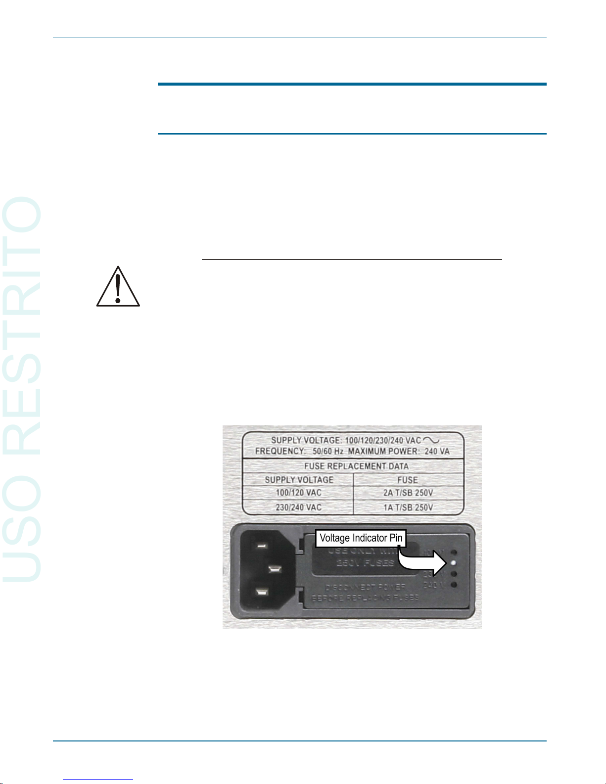
The mains power supply is applied to your 2700 series instrument through
the power entry module located on the rear panel. Before connecting the
power cord, confirm that the input voltage selection and fusing arrangement in
the power entry module are correct for your mains power supply.
Chapter 2: Installation and Setup for APIB Setting Up the Hardware
10 Getting Started with Your 2700 Series Instrument
Figure 2. Detail, power entry module on 2700 series instrument rear panel.
USO RESTRITO
This manual suits for next models
4
Table of contents
Other Audio Precision Test Equipment manuals

Audio Precision
Audio Precision ATS-2 User manual

Audio Precision
Audio Precision AECM206 User manual

Audio Precision
Audio Precision System Two User manual

Audio Precision
Audio Precision ATS-1 User manual

Audio Precision
Audio Precision Portable One Dual Domain User manual

Audio Precision
Audio Precision ATS-2 User manual

Audio Precision
Audio Precision Portable One Plus Access User manual


