Audio Precision ATS-2 User manual

Getting Started with Your ATS-2
ATS-2


Getting Started
with ATS-2
An Introductory Guide to ATS-2
APIB and GPIB Configurations

No part of this manual may be reproduced or transmitted in any
form or by any means, electronic or mechanical, including
photocopying, recording, or by any information storage and
retrieval system, without permission in writing from the
publisher.
Audio Precision®, System One®, System Two™, System Two
Cascade™, System One + DSP™, System Two + DSP™, Dual
Domain®, FASTTEST®, APWIN™, ATS™ and ATS-2™ are
trademarks of Audio Precision, Inc. Windows® is a trademark
of Microsoft Corporation.
Published by:
5750 SW Arctic Drive
Beaverton, Oregon 97005
Tel: 503-627-0832
Fax: 503-641-8906
US Toll Free: 1-800-231-7350
email: [email protected]
Web: audioprecision.com
Printed in the United States of America
Copyright Ó2001–2004 Audio Precision, Inc.
All rights reserved.
Audio Precision PN 8211.0136 Revision 3
IV1011152010

Contents
Safety Information...........................v
Safety Symbols ............................vi
Disclaimer ...............................vi
Chapter 1
General Information ..........................1
ATS-2: An Overview...........................1
ATS-2 Capabilities............................2
Conceptual Architecture of ATS-2 ..................3
About This Manual ...........................4
Online Help ...............................4
Other Documentation for ATS-2 ...................4
ATS-2 User’s Manual .........................4
AP Basic User’s Guide and Language Reference .........5
AP Basic Extensions Reference for ATS-2 .............5
Filter Design Package Manual....................5
Other Publications ..........................5
GPIB Documentation for ATS-2 ...................5
Chapter 2
Installation and Setup for APIB ...................7
ATS-2 Components ...........................7
Getting up and Running .......................8
Installing ATS Software on a PC ....................8
PC System Requirements ......................8
Installing the Software .......................8
Setting Up the ATS-2 Hardware ....................9
Connecting ATS-2 to the Electrical Mains Supply .........9
Checking the Mains Supply Voltage Configuration ......10
Opening the Power Entry Module ...............10
Changing the Mains Supply Voltage Configuration......10
Fuse Information ..........................12
Getting Started with ATS-2 i

Changing the Fusing Arrangement ..............12
Connecting ATS-2 to Your PC ....................13
Installing a PCI APIB Card......................13
Using the PCM-WIN PCMCIA Interface Card ............14
Chapter 3
Hardware Overview..........................15
ATS-2 Front Panel ...........................15
ATS-2 Rear Panel............................16
Chapter 4
ATS-2 User Interface .........................19
Overview................................19
A Note on Nomenclature ......................19
Starting up the ATS Software ....................20
ATS Workspace ............................20
ATS Panels ...............................21
Panel Settings............................22
Panel Readings ...........................22
ATS Menus ...............................23
File Menu ..............................23
Edit Menu ..............................23
View Menu..............................23
Panels Menu.............................23
Sweep Menu ............................23
Compute Menu ...........................24
Macro Menu .............................24
Utilities Menu ............................24
Window Menu ...........................24
Help Menu..............................24
Status Bar ...............................24
Toolbars and Buttons ........................25
Standard Toolbar ..........................25
Panels Toolbar ...........................25
Macro Toolbar ...........................25
Learn Mode Toolbar ........................26
Quick Launch Toolbar .......................26
Using Files with ATS..........................26
Test Files...............................26
Macro Files .............................27
Data Files ..............................27
Waveform Files ...........................27
Log File ...............................28
Downloadable Filter Files .....................28
ii Getting Started with ATS-2

Chapter 5
Quick Guides ..............................29
Introduction .............................29
Quick Guide to the Analog Signal Path ...............29
Analog Input Panel .........................29
Analog Generator Panel ......................29
Analyzer Panel ...........................30
Signal Monitor ...........................31
Controlling the Analog Generator ................31
Units .................................32
Quick Guide to Sweeps ........................33
Sweep Fundamentals .......................34
Settings and Readings ......................34
Source Range, Steps, and Spacing ...............35
Data Display Range ........................35
Example Sweep: Frequency Response ..............36
Review...............................36
Example Sweep: Amplitude Linearity ..............37
Quick Guide to the FFT Spectrum Analyzer ............38
Real-Time vs. Batch-Mode Instruments..............38
The FFT Concept ..........................39
Setting up an FFT ..........................39
Panel Fields ............................40
Time vs. Frequency .......................40
Quick Sweep Setup........................40
Fine-Tuning the Display .....................41
Saving and Loading Tests ......................42
The Next Step .............................42
Chapter 6
Specifications .............................43
Chapter 7
GPIB Configuration ..........................57
Introduction .............................57
APIB or GPIB? ............................57
The GPIB Software Development Process .............58
Using both GPIB and APIB for Software Development .....60
Establishing GPIB Communication ................61
GPIB Connection .........................61
ATS-2 GPIB Address and I/O Mode Switch ...........63
GPIB Status LEDs .........................65
GPIB Program Message Terminators ..............65
Getting Started with ATS-2 iii

iv Getting Started with ATS-2

Safety Information
Do NOT service or repair this product unless properly qualified.
Servicing should be performed only by a qualified technician or an
authorized Audio Precision distributor.
Do NOT defeat the safety ground connection. This product is designed
to operate only from a 50/60 Hz AC power source (250 V rms maximum)
with an approved three-conductor power cord and safety grounding. Loss
of the protective grounding connection can result in electrical shock hazard
from the accessible conductive surfaces of this product.
For continued fire hazard protection, fuses should be replaced ONLY
with the exact value and type indicated on the rear panel of the instrument
and discussed on page 12 of this manual. The AC voltage selector also
must be set to the same voltage as the nominal power source voltage (100,
120, 230, or 240 V rms) with the appropriate fuses. Different fuses are
required depending on the line voltage.
The International Electrotechnical Commission (IEC 1010-1) requires
that measuring circuit terminals used for voltage or current measurement
be marked to indicate their Installation Category. The Installation Category
is defined by IEC 664 and is based on the amplitude of transient or
impulse voltage that can be expected from the AC power distribution
network. This product is classified as INSTALLATION CATEGORY II,
abbreviated “CAT II” on the instrument front panel.
Do NOT substitute parts or make any modifications without the written
approval of Audio Precision. Doing so may create safety hazards.
This product is for indoor use—pollution degree 2.
Getting Started with ATS-2 v
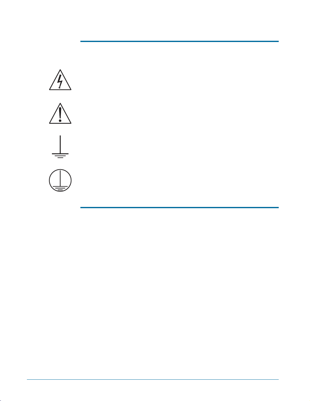
Safety Symbols
The following symbols may be marked on the panels or covers of
equipment or modules, and are used in this manual:
WARNING!—This symbol alerts you to a potentially hazardous
condition, such as the presence of dangerous voltage that could pose a risk
of electrical shock. Refer to the accompanying warning label or tag, and
exercise extreme caution.
ATTENTION!—This symbol alerts you to important operating
considerations or a potential operating condition that could damage
equipment. If you see this marked on equipment, refer to the Operator’s
Manual or User’s Manual for precautionary instructions.
FUNCTIONAL EARTH TERMINAL—A terminal marked with this
symbol is electrically connected to a reference point of a measuring circuit
or output and is intended to be earthed for any functional purpose other
than safety.
PROTECTIVE EARTH TERMINAL—A terminal marked with this
symbol is bonded to conductive parts of the instrument and is intended to
be connected to an external protective earthing system.
Disclaimer
Audio Precision cautions against using their products in a manner not
specified by the manufacturer. To do otherwise may void any warranties,
damage equipment, or pose a safety risk to personnel.
vi Getting Started with ATS-2
Chapter 1
General Information
ATS-2: An Overview
The Audio Precision ATS-2 is a powerful computer-controlled audio test
and measurement system consisting of two key components:
§The ATS-2 hardware: the connectors and circuitry necessary for
precise signal generation and analysis, and for interfacing to devices.
The hardware is mounted in a compact (2 U) aluminum and steel
chassis that can be installed in a standard equipment rack using
optional mounting hardware.
§The ATS measurement software, which runs on a personal computer
(PC), and provides the control, display, report and automation
functions for the ATS-2 system. The ATS software will run under
Microsoft Windows 2000 and Windows XP.
With the exception of the mains power switch on the rear panel, there
are no knobs, dials, controls, readouts, meters or switches on the ATS-2
chassis. All of these functions are performed via the ATS software on the
controlling PC.
Getting Started with ATS-2 1
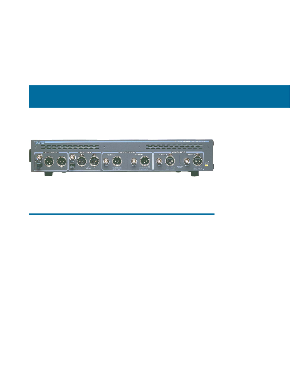
Figure 1. The Audio Precision ATS-2 audio test and measurement system.

The PC communicates with the ATS-2 chassis via a proprietary bus
interconnection called the Audio Precision Interface Bus (APIB), which
requires a dedicated cable and a PC-mounted interface card or adapter.
APIB interfaces can be ordered as PCI and PCMCIA compatible devices.
See Chapter 2 for further information on APIB and interface hardware.
When ordered in the optional GPIB configuration (ATS2G), ATS-2 can
also be controlled by the industry-standard IEEE 488.2 General Purpose
Interface Bus (GPIB). See Chapter 7 for more information about the
ATS-2 GPIB configuration.
ATS-2 Capabilities
§ATS-2 can make amplitude, frequency, THD+N, noise, phase,
crosstalk, bandpass, and IMD measurements for analog or digital
audio devices. In a special function, ATS-2 can perform detailed
analysis and measurement of harmonic distortion products.
§ATS-2 can perform complex sweeps, and display and print the results
with a powerful graphing engine. ATS-2 offers control over
instrument regulation and settling parameters. Data obtained from
sweeps can be compared to pre-defined limits. A variety of
computations can be performed on the measured data after
acquisition. Tests and data can be saved and recalled, and ATS-2
measurements can be automated by macros written in the AP Basic
programming language.
§ATS-2 can perform measurements using fast Fourier transform (FFT)
analysis. Advanced high-speed FFT analysis techniques are available,
including multitone recognition and analysis, frequency adjustment
for bin centering, synchronous FFT processing, and advanced
post-FFT analysis.
§ATS-2 can examine an AES/EBU digital interface signal and assure
the integrity of digitally transmitted data. It can also measure and
examine the jitter in the waveform. ATS-2 can extract a variety of
statistics from a digital waveform, including the sample rate, the
interface waveform voltage, the jitter amplitude, and the active and
inactive data bits. ATS-2 also has the capability of transmitting and
receiving a full complement of AES/EBU status bits.
§ATS-2’s sample rate may be synchronized to an external AES/EBU
signal, a square wave, or an NTSC or PAL video source.
§ATS-2 has two auxiliary control connectors for control of external
equipment.
Chapter 1: General Information ATS-2 Capabilities
2 Getting Started with ATS-2

Conceptual Architecture of ATS-2
The functional components implemented in ATS-2 include two audio
signal generators, an audio signal analyzer, digital and analog input and
output modules, and a module for external timebase synchronization.
All signal generation is performed in the digital domain. One of the two
signal generators is dedicated to the digital output. The signal from this
digital generator is buffered and conditioned for the balanced, unbalanced
and optical outputs. The output of the second signal generator is
converted to an analog signal by a digital-to-analog converter (DAC). The
two-channel output of the DAC is conditioned and ranged for the
balanced and unbalanced analog outputs.
All signal analysis is also performed in the digital domain. The digital
input is buffered and directly applied to the analyzer. Analog inputs are first
ranged and conditioned, and then digitized by a high-resolution
analog-to-digital converter (ADC) before being applied to the analyzer. An
optional high-bandwidth ADC is available to increase measurement
bandwidth.
Conceptual Architecture of ATS-2 Chapter 1: General Information
Getting Started with ATS-2 3
Analog Domain vs. Digital Domain
Analog audio signals are electrical analogies of the sound waves
that they represent, varying in frequency and amplitude in a continuous
fashion. In analog audio electronics, these voltages and currents are
manipulated, processed, and measured by modifying their amplitude or
frequency. The term analog domain refers to signals represented and
processed in this fashion.
Digital audio signals, on the other hand, are numerical
representations of the sound waves. The representation is often carried
on an electrical signal called the interface signal. Digital audio is
processed mathematically in processes gathered together under the
name of Digital Signal Processing,orDSP. The term digital domain
refers to signals represented and processed in this fashion.

About This Manual
You’re reading Getting Started with ATS-2. This manual describes how
to set up the ATS-2 hardware and ATS software. It also contains a quick
tutorial to familiarize you with the system. It is organized as follows:
§Chapter 2: Software installation and hardware setup information.
§Chapter 3: Description of the hardware and its connectors.
§Chapter 4: Description of the user interface.
§Chapter 5: Introductory tutorial.
§Chapter 6: Specifications.
§Chapter 7: GPIB Configuration.
Online Help
Much of the information contained in the ATS-2 User’s Manual is also
available in the online help system included in the ATS software. You can
access the help system in two ways:
§ATS has context-sensitive help. Almost every control and display on
each software panel has a help topic associated with it. To view the
topic, click on the field or control, then press the F1 function key.
§On the Menu bar, click Help. The Help menu offers commands to
search the Help Index, browse through the Help Topics, or select
a specific help library such as AP Basic Language.
Other Documentation for ATS-2
Audio Precision publishes a variety of documents, many in electronic
form, about hardware and software products, audio theory, and test and
measurement techniques. The following list describes the documents that
are included as Adobe Acrobat Portable Document Format (PDF) files on
the CD-ROM that comes with your instrument. They can also be
downloaded from our Web site at audioprecision.com.
ATS-2 User’s Manual
The ATS-2 User’s Manual is the primary operation and reference
manual for the system. Consult the ATS-2 User’s Manual for:
§Detailed descriptions of every ATS-2 feature, software panel, control,
and display.
§Reference information on audio test and measurement techniques,
sample and utility file listings, and an audio glossary.
Chapter 1: General Information About This Manual
4 Getting Started with ATS-2

AP Basic User’s Guide and Language Reference
You can create tests and macros to automate your measurements.
Macros are written in the AP Basic programming language, which is a
subset of Microsoft® Visual Basic®. The AP Basic User’s Guide and
Language Reference contains a list of the AP Basic commands, each with a
full description and examples of usage.
AP Basic Extensions Reference for ATS-2
The AP Basic Extensions Reference for ATS-2 contains a list of
OLE/ActiveX automation commands that control the specific features of
the ATS-2 hardware and the ATS software.
Filter Design Package Manual
ATS-2 can access and use downloadable filter files. This feature allows
you to install custom software high-pass, low-pass and weighting filters for
use with the ATS-2 analyzer.
The ATS CD-ROM includes a version of Momentum Data Systems’
QEDLite filter design package. This special version creates filter files in the
format used by ATS. The Filter Design Package manual describes the
operation of this software.
Other Publications
Audio Precision publishes application notes, tech notes, technical papers
and training materials that cover all aspects of audio test and
measurement. Information about our library of technical papers and
announcements of new papers is available from Audio Precision Technical
Support, and on the Audio Precision Web site.
GPIB Documentation for ATS-2
When ordered in the optional GPIB configuration, ATS-2 can also be
controlled by the industry-standard General Purpose Interface Bus (GPIB).
Basic installation with GPIB is covered in Chapter 7 of this manual. For
GPIB development and programming, order the ATS-2 GPIB
Programmer’s Reference Manual, which includes a CD-ROM with GPIB
sample program files.
Other Documentation for ATS-2 Chapter 1: General Information
Getting Started with ATS-2 5

Chapter 1: General Information Other Documentation for ATS-2
6 Getting Started with ATS-2

Chapter 2
Installation and Setup for APIB
ATS-2 Components
The following items are included with a standard, APIB-configured
ATS-2. For a GPIB-configured ATS-2, refer to Chapter 7.
§The ATS-2 hardware chassis.
§A mains power cord.
§A packet of miscellaneous printed materials.
§A box containing the ATS-2 WIN-KIT interface kit.
The following items are contained within the ATS-2 WIN-KIT:
§This manual, Getting Started with ATS-2.
§The ATS-2 User’s Manual.
§An Audio Precision Interface Bus (APIB) interface card, as ordered1.
§An APIB interface cable.
§The ATS control software CD-ROM, containing the ATS
measurement software and documentation files.
§The Tones and Tests CD-ROM, containing audio test tones and
sample files.
We recommend that you retain the shipping box and packing materials
to protect your instrument if you need to ship it in the future.
Getting Started with ATS-2 7
1The ATS-2 APIB interface card is available for PCI and PCMCIA slots. Refer to Page 13 for detailed
installation information.

Getting up and Running
There are three main tasks to setting up ATS-2:
§Installing the ATS software on a personal computer (PC);
§Configuring ATS-2 for the local power supply; and
§Installing the APIB card in the PC and connecting it to ATS-2.
These tasks are described below.
Installing ATS Software on a PC
PC System Requirements
ATS-2 needs to be connected to an IBM-compatible PC to operate. The
PC must have the following minimum features and capabilities:
§A CD-ROM drive.
§Microsoft Windows 2000 or Windows XP operating system.
§The minimum processor for your operating system, typically a
Pentium-compatible running at 133 MHz or faster for Windows 2000,
or 233 MHz or faster for Windows XP.
§The minimum RAM for your operating system, typically 64 MB for
Windows 2000 or 128 MB for Windows XP.
§An open PCI or PCMCIA slot to mount the APIB interface card.
§At least 30 MB of free hard disk space; as much as 100 MB if all
utilities, documentation and sample files are to be installed.
§A color monitor and a video card with at least VGA capabilities.
Video resolution of 1024´768 is recommended.
You will also need signal interface cables to connect ATS-2 to your
device for testing. Since there are many possible connection
configurations, signal cables are not provided with ATS-2. Audio Precision
offers cable kits with common connectors and adapters for purchase.
Contact a sales representative or Audio Precision Technical Support for
more information.
Installing the Software
To install the ATS software, use the following procedure:
§Close all Windows programs.
§Insert the ATS CD-ROM into the CD-ROM drive. The installation
program should start automatically. If it does not, click on the Start
Chapter 2: Installation and Setup for APIB Getting up and Running
8 Getting Started with ATS-2

menu and choose Run. Click Browse and choose the file Setup.exe
on the ATS CD-ROM. Click OK in the Run dialog box.
§In the main menu, click Install ATS Software. Follow the on-screen
instructions. The installation program prompts you to enter the
required information.
§The installer may prompt you to reboot the machine. Although you
do not need to reboot immediately, you must reboot before you can
use the ATS-2 hardware.
Setting Up the ATS-2 Hardware
Connecting ATS-2 to the Electrical Mains Supply
ATS-2 must be connected to a 50–60 Hz alternating current (AC)
electrical mains supply, maximum voltage 250 Vrms.
The units are configured at the factory for the expected voltage at their
intended destination. The voltage setting and fusing arrangement will
normally be correct unless the unit has been transported into another area.
The power entry module has a strip of indicator tape showing its mains
voltage setting. This tape must be removed before use.
You MUST be sure that the ATS-2 mains power configuration
is correct for the electrical mains power supplied in your area.
If you are not sure, do not plug ATS-2 in to the mains power.
Follow the instructions below to check or change the ATS-2
mains supply voltage selection.
The mains power supply is applied to ATS-2 through the power entry
module located on the rear panel. Before connecting the power cord,
Setting Up the ATS-2 Hardware Chapter 2: Installation and Setup for APIB
Getting Started with ATS-2 9
Figure 2. Detail, power entry module on ATS-2 rear panel.
confirm that the input voltage selection and fusing arrangement in the
power entry module are correct for your mains power supply.
Checking the Mains Supply Voltage Configuration
The voltage indicator pin protrudes through one of the four labeled
holes in the module cover to indicate the selected input voltage, as shown
in Figure 2. Check that the indicated voltage matches your mains supply
voltage.
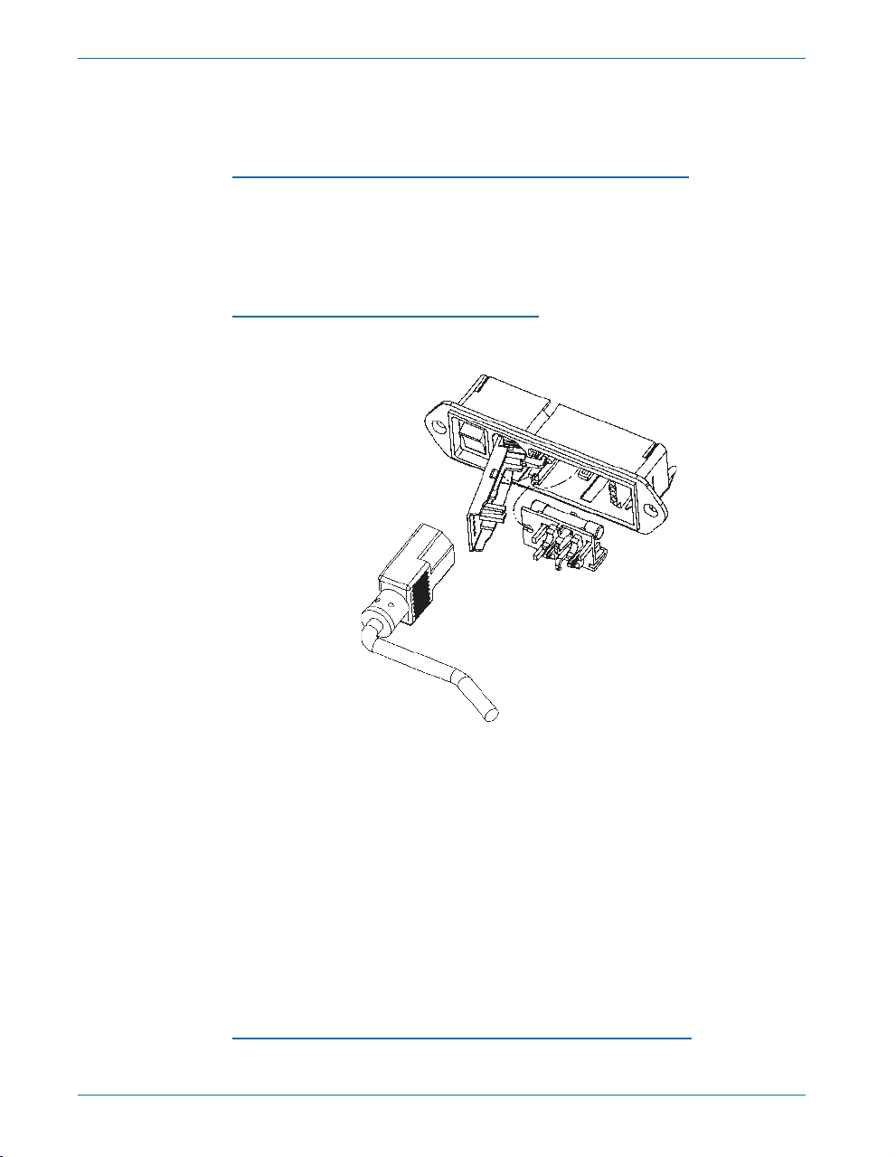
Opening the Power Entry Module
Unplug the power cord from the instrument before changing fuses or
performing any other operations described in this section.
To open the Power Entry Module, refer to Figure 3 and proceed as
follows:
§Remove the mains power supply cord from the power cord
connector.
§Locate the slot in the module cover door hinge. The hinge is a the
left side of the cover door, and the slot in the hinge is visible in the
power cord connector cavity. Insert a small screwdriver or similar tool
in the slot and pry the cover door hinge outward. The cover door will
snap out, and then can be pivoted on its hinge for access to the fuse
block assembly and voltage selector card.
Changing the Mains Supply Voltage Configuration
§Open the Power Entry Module as described above.
Chapter 2: Installation and Setup for APIB Setting Up the ATS-2 Hardware
10 Getting Started with ATS-2
Figure 3. Power entry module door and fuse block.
Other manuals for ATS-2
1
Table of contents
Other Audio Precision Test Equipment manuals

Audio Precision
Audio Precision ATS-2 User manual

Audio Precision
Audio Precision Portable One Dual Domain User manual

Audio Precision
Audio Precision ATS-1 User manual

Audio Precision
Audio Precision Portable One Plus Access User manual

Audio Precision
Audio Precision System Two User manual

Audio Precision
Audio Precision AECM206 User manual

Audio Precision
Audio Precision 2700 Series User manual


