Audio Solutions Sound Project 3 User manual

USER MANUAL
@ 2015-2020 Audio Solution
S.P.3. User Manual ver. 5.2
DJ ROTARY MIXER
S.P.3.
(Sound Project model 3)

INDICE
3 REFERENCES
4 WARNINGS
5 GENERAL
6 CONTROLS
8 ISOLATORS
9 CONNECTIONS
11 RULES OF USE
12 TECHNICAL SPECIFICATIONS
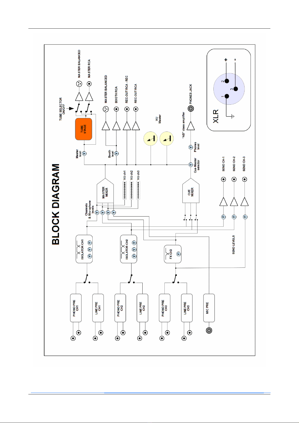
13 BLOCK DIAGRAM
14 - WARRANTY
Audio Solution - S.P.3 manuale utente 2

REFERENCES
Copyright @ AudioSolution.
All software, if present, is licensed and owned by AudioSolution.
Information in this publication supersedes the previously published manuals referred to the same product
unless specifically written.
THIS MANUAL:
First printing january 015
Revision march 0 0 – Ver. 5.
Contacting AudioSolution
AudioSolution
Via Firenze, 41
36070 – Castelgomberto (VICENZA)
Italy
Email: inf[email protected]
Web: www.audiosolution.it
Product information:
For product directly sold by AudioSolution send email to: [email protected]t
For product sold by others do contact the reseller in your area.
Audio Solution - S.P.3 manuale utente 3

WARNINGS
IT IS VERY IMPORTANT TO READ THE FOLLOWING SAFETY RULES!
SAVE THIS MANUAL FOR FUTURE USE
! - CAREFULLY set the SEELECTOR for the working voltage (110-220V) placed in the panel below, failure to
comply can damage the mixer
! - Do not use the mixer near hot sources or open flames
! - Do not use it in rain or very high humidity
! - Keep liquid substances away and prevent them from dripping onto the mixer, it is not waterproof!
! - Clean it only when switched off without cables connected
! - Make sure to leave some space around the mixer (at least 4 cm) for natural ventilation
! - The casing of the mixer is connected to the general ground for your safety, make sure that the electrical
system is up to standard to make it effective.
! - Only connect sources and accessories that have the correct requirements, specified in this manual in the
"technical specifications" section
! - DO NOT open the mixer, it is risky and there are no user parts inside, always refer to qualified personnel
when necessary
! - Turn up the volume carefully for the safety of your own and others' hearing systems
! - Read this manual before using the mixer
Audio Solution - S.P.3 manuale utente 4

GENERAL
We thank you and congratulate you on your preference, the AudioSolution team.
The SP3 is a 3-channel rotary personal mixer, the two main ones are equipped with isolator-type tone control and can
accept LINE or PHONO inputs, while the third, again with the LINE or PHONO option, has a special cut filter, which
excludes high or low frequencies in a linear way with a potentiometer.
It has a microphone input, a REC output, a “REC no mic” output and SEND-RETURN management for any external
effects with RCA connectors while the MASTER and BOOTH outputs have both RCA and balanced XLR connections.
GENERAL:
–Fully analog implementation for reference audio quality.
–“OLD STYLE” design to recall the shapes and colors of the first mixers but with a touch of Italian design.
–Powder coated metal frame with handcrafted solid wood bulkheads.
–High power headphone output made with discrete HQ components.
–“PAN-control” function to vary the listening source with headphones between the channels and the
MASTER:
–Separate linear power supply for audiophile sound.
–0 Volt or 110 Volt operation selectable.
–Separate power supplies for Audio section, vumeter section and auxiliary section (relay).
–Analog stereo Vu-meter section to independently monitor the channels in the master.
–Independent Vu-meter section for each channel.
–BNC connector for courtesy light (1 Volt).
–Compact size and weight to be easily transported.
Audio Solution - S.P.3 manuale utente 5

CONTROLS
1 - ISOLATOR 1, channel 1 (CH-1) is internally divided into 3 bands by a purely analog crossover, the potentiometers set
the level of each band (see section ISOLATORS).
- ISOLATOR , channel (CH- ) is internally divided into 3 bands by a purely analog crossover, the potentiometers set
the level of each band (see section ISOLATORS).
3 - Vumeter RH and LH, the backlight indicates that the mixer is on.
4 - BNL socket for courtesy light 1 Volt d.c. (+/- 0%) the positive is the central part of the connector, the negative is its
casing, see image on the next page.
5 - Controls for the SEND to be sent to the eventual effects box, the SENS is independent for each channel.
6 - Volume control for CH1, CH and CH3, each channel has its own independent vumeter to better manage the levels
without risking saturation; the last blue LED indicates the maximum limit, when it turns on the distortion is already
over 10%.
7 - CUE selector to send the signal of the corresponding channel (CH-1, CH- , CH-3) to the headphone amplifier, each
selector is to the left of the corresponding channel knob.
Audio Solution - S.P.3 manuale utente 6
1 2 4
11
12
13
14
5
6
7
8
9
3
10
15

8 - Potentiometer to adjust the tone control of channel 3 (CH-3), in a clockwise direction the low frequencies are
reduced proportionally by increasing the highs, while, in an anticlockwise direction, the high ones are decreased to
increase the lows. In the central position the channel does not undergo equalization.
9 - Potentiometer to select the headphone signal, anticlockwise for the direct output of the channel while clockwise
for the master output, by turning it it is possible to mix the two signals in the headphones.
10 - Potentiometer for selecting the volume in the headphones, ATTENTION: the amplifier is powerful, do not
exaggerate with the volume to safeguard your hearing system and your headphones.
11 - Potentiometer for microphone volume control.
1 - Potentiometer to dose the intensity of the external effects, it controls the input coming from the RETURN of the
eventual effects box and sends it to the output.
13 - Potentiometers to dose the volume at the MASTER and BOOTH outputs, adjust the amount of the signal to be sent
to the amplification system connected to the MASTER and BOOTH output. The TUBE section is present only in the
MASTER section and controls both the unbalanced and balanced output.
14 - Selectors to select the LINE or PHONO input for each channel (CH-1, CH- , CH-3), the input selection is available
directly from the main panel, without having to access the rear to do so, moreover switching occurs through relays to
improve the audio path and therefore the quality of the same.
15 - Output for stereo headphones (6.3mm JACK).
BNC connector for courtesy lamp
Audio Solution - S.P.3 manuale utente 7
+
-
HIGHMIDLOW
CH-2
+6dB +6dB +6dB
CH-1
+6dB +6dB +6dB
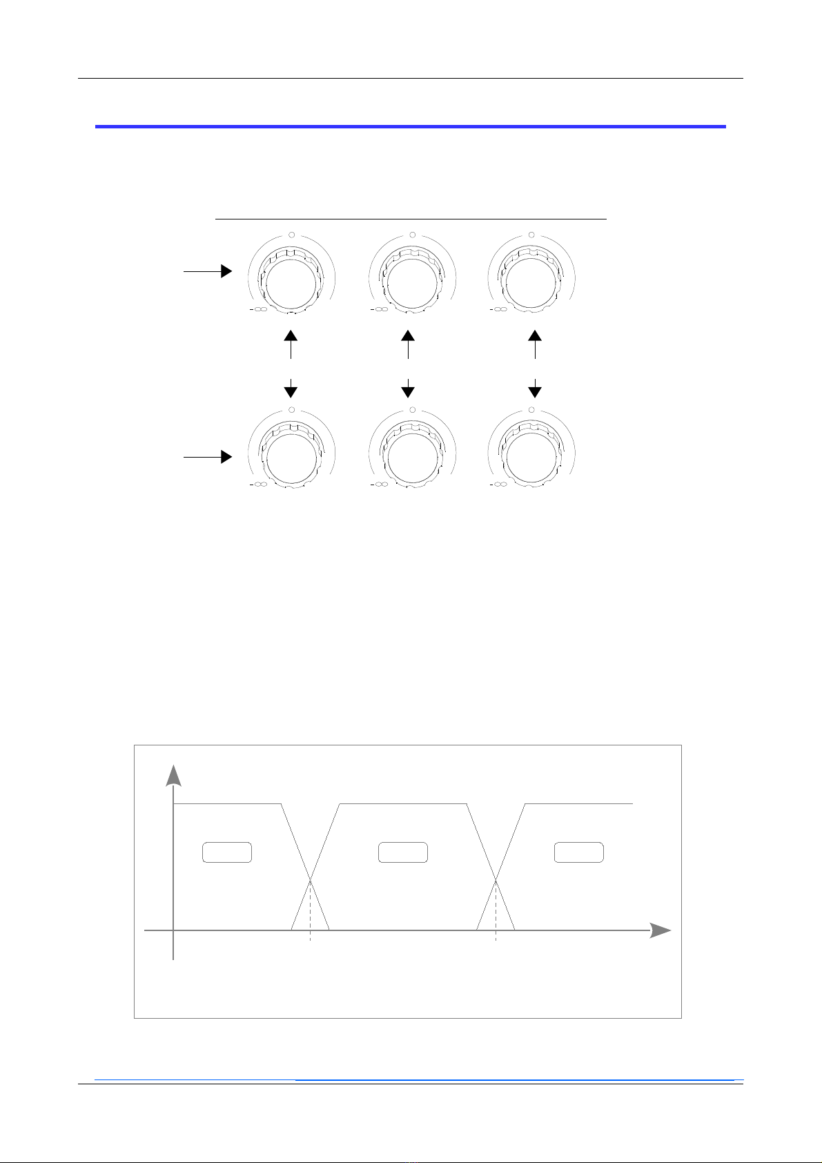
ISOLATORS
The first line of knobs at the top relates to the Channel 1 (CH-1) isolator control, while the second line of knobs at the
bottom relates to the Channel (CH- ) isolator.
The knobs on the left drive the low frequencies (LOW) and cover the 0-300Hz band, the central ones (MID) operate in
the 300-4000Hz band while those on the left (HIGH) from 4000 to 50000Hz.
The center point, indicated by “0” (zero), indicates no attenuation or emphasis of the audio band
By turning the knob counterclockwise, the portion of the band relative to the knob will be attenuated until it reaches
zero, while turning the knob clockwise will emphasize the band relative to the knob until it reaches + 8dB.
Audio Solution - S.P.3 manuale utente 8
CH-1
CH-2
Freq.
dBV
300 Hz 4000 Hz
LOW MID HIGH

CONNECTIONS
Respect the connections and use good quality cables to guarantee the best performance!
WARNING! Check the 115/230 V selector in the power supply
before connecting it to the mains
1 - Socket for power supply, to be connected to the power supply, select 115 or 30V in the lower part of the power
supply itself with selector to select the the voltage of your country then connect the 5-pole connector to the mixer as
described on the following page.
- Valve ventilation opening, do not obstruct the air passage.
The valve works at about 130V dc, DO NOT open the mixer and do not insert objects of any kind into the slots.
3 - Selector to activate / deactivate the tube stage.
This feature has been designed not to interrupt your mixing session if the valve runs out, or if you prefer to use the
mixer without the valve.
4 - Terminal for ground connection (GND) when using turntables.
Audio Solution - S.P.3 manuale utente 9
12 5 6
7
8
3
4109 11 12

5 - Unbalanced BOOTH-MASTER output with RCA connections.
6 - Balanced output with XLR connections for BOOTH and MASTER, the connections are: 1 = GND, = HOT, 3 = COLD
(see the BLOCK DIAGRAM paragraph).
7 - Microphone input.
8 - REC output for recording and “-mic” for recording without a signal coming from the microphone.
9 - SEND output and RETURN input for connecting external effects.
10 - LINE and PHONO input for channel 3
11 - LINE and PHONO input for channel
1 - LINE and PHONO input for channel 1
Power supply
Audio Solution - S.P.3 manuale utente 10
IMPORTANTE
Sostituire il fusibile con uno di identico modello:
250V 500mA - Timed
5 pole
connector,
do connect
to the mixer
Switch
ON/OFF
Light ON
115/ 30V
Socket IN
Fuse are in the bottom
side of the socket.
Unplug the cable and
open it pulling the plastic
with a flat screwdriver.

RULES OF USE
To ensure maximum performance and avoid unexpected breakdowns, it is good to read the following points:
1 - Before connecting any connector, check the position of the switch for the 115/ 30 Volt selection which is
located under the mixer.
- To switch on the audio system, follow these steps to avoid annoying noises:
–Bring the MASTER and BOOTH volumes to zero
–Turn on the MIXER
–Turn on the audio amplification system
3 - To turn off the audio system, follow these steps to avoid annoying noises:
–Bring the MASTER and BOOTH volumes to zero
–Turn off the audio amplification system
–Turn off the MIXER
4 - For a first calibration, proceed as follows:
–Turn on the mixer following the procedure described above.
–Activate a source on any of the channels.
–Turn the potentiometer of the corresponding channel until the maximum peaks of the song come to
light up all the green LEDs of the main stereo vu-meter at the top left.
–Raise the volume of the MASTER until reaching the maximum performance of the system before
distortion, then memorize the position of the potentiometer (for example 6) then reset the volume to
zero.
–Raise the volume of the BOOTH (if used) until reaching the maximum performance of the system before
the distortion, then memorize the position of the potentiometer (for example 4) then bring the volume
back to zero.
–Return all the potentiometers of the channels to zero and then the MASTER and BOOTH potentiometers
just before the position found above (in the previous example just before 6 for the MASTER and just
before 4 for the BOOTH).
–Now you can operate with the various volumes until the red LEDs of the main vu-meter light up.
Obviously it is possible to perform the same calibration with a different number of lit LEDs, if you want to
operate up to the use of the red LEDs it is possible as the mixer does not introduce distortion to the full scale of
the vu meter.
5 - Use good quality cables to ensure maximum audio performance.
Audio Solution - S.P.3 manuale utente 11
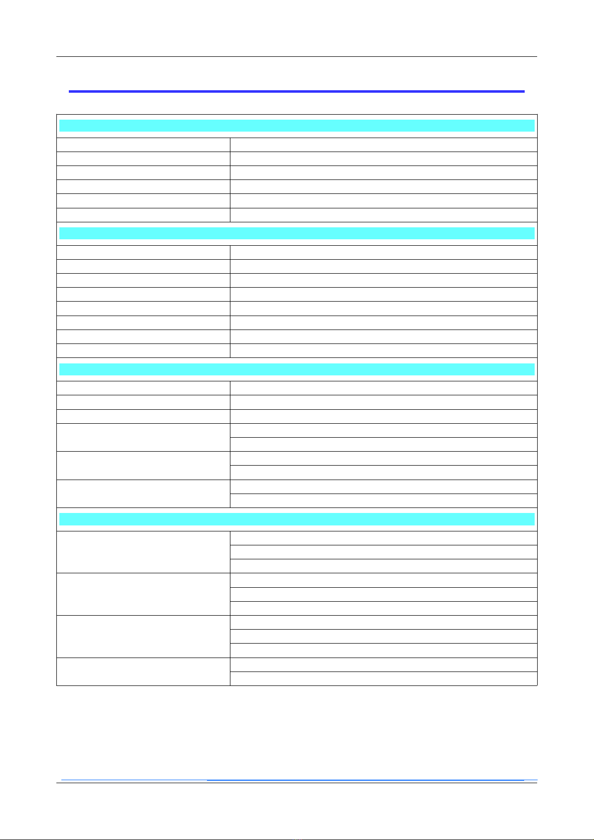
TECHNICAL SPECIFICATIONS
GENERAL
Power consumption: 40 Watt max
Operation voltage: 110 Volt o 0 Volt selectable
Working temperature: 0°C – 40°C (3 °F – 104°F)
Humidity permissible when working 5% - 80% senza condensa
Weight: 4,8 Kg without package
Dimensions: L=340mm P=300mm H=100mm
CONNECTIONS
Input CH1: PHONO o LINE selectable
Input CH2: PHONO o LINE selectable
Input CH3: PHONO o LINE selectable
Master OUT: RCA stereo e XLR stereo for balanced
BOOTH OUT: RCA stereo e XLR stereo for balanced
REC OUT: RCA stereo
MIC input: Jack 6,3mm mono + XLR
Headphone OUT: Jack 6,3mm stereo
AUDIO
Number of channels: 3 stereo + 1 mic mono
Frequency response: 18Hz -- 30000Hz (+1dB/-3dB) @ 4dBu on 1000 Ω
Distortion (THD+N): < 0,05% @ 1V @ 1000 Ω
Input PHONO:
Impedence: 47 KOhm
Standard sensitivity 10mV (-4 dBu) – minimum to reach the peak: mV (-5 dBu)
Input LINE:
Impedence: >30 KOhm
Standard sensitivity 1V ( dBu) - minimum to reach the peak: 0,3V (-8dBu)
Ingresso MICROFONO:
Impedence: 10 KOhm
Standard sensitivity 5mV (-44dBu)
OUTPUTS
MASTER:
Output impedance RCA e XLR: 100 Ohm – Nominal impedance 600 Ohm
Standard level out RCA: 1, V (+4dBu) - Standard level out XLR: ,44V (+10dBu)
Output maximum level before clip: RCA:10,5V (+ dBu) - XLR: 1V ( 8dBu)
BOOTH:
Output impedance RCA e XLR: 100 Ohm - Nominal impedance 600 Ohm
Standard level out RCA: 1, V (+4dBu) - Standard level out XLR: ,44V (+10dBu)
Output maximum level before clip: 10,5V (+ dBu)
REC-OUT:
Output impedance : 600 Ohm – Nominal impedance 10K Ohm
Standard level out: 0, V (-1 dBu)
Maximum level out: V (+8dBu)
CUFFIE:
AB class amplifier build with dicrete components
Power: >70mW @ 50 Ohm
The specifications can be different due to updates or modifications of the product.
Audio Solution - S.P.3 manuale utente 12
Audio Solution - S.P.3 manuale utente 13

WARRANTY
WARRANTY - ITALY
The S.P.3 mixer is covered by a warranty for a period of 4 months if purchased directly or through affiliated stores and if installed and operated
correctly. Audio Solution guarantees the repair or replacement with a model of comparable value at its discretion and free of charge for both spare
parts and labor, the shipping costs will be paid by the customer.
The warranty period begins and is valid from the date shown in the box below if accompanied by the stamp authenticated by the signature of the
retailer and the receipt.
WARRANTY - FOREIGN
For products sold directly by AudioSolution, the same applies as for the Italian warranty, for products sold by our resellers please refer to them for
the various and possible clauses.
The warranty is not liable if:
–Damage resulting from alterations and modifications not expressly authorized by AudioSolution, misuse of the product, lightning strikes,
incorrect or defective power sources.
–Personal damage caused by excessive volume and misuse.
–Defects or damage caused by the use of non-original parts or unauthorized labor.
–Products with the serial number removed.
Technical support: [email protected]
Audio Solution - S.P.3 manuale utente 14
STAMP
PURCHASE DATE (D/M/Y)
SERIAL NUMBER
Table of contents


