Audio Solutions AS-P-601 User manual

POWER SOLUTION 1000
Home Theater Power Center
User Guide
Model AS-P-601
© Copyright 2011 Metra Electronics
The informa on contained herein is subject to change without no ce.
This document contains proprietary informa on protected by copyright law.
No part of this document may be photocopied or reproduced without prior
wri en consent.
audiosolu ons.com

TABLE OF CONTENTS INTRODUCTION
Thank you for purchasing the Power Soluon 1000. Your new home theater power
soluon provides clean AC power to sensive home theater electrical equipment.
Four always on plus four switched outlets (eight total) provide premium digital and
analog output with surge protecon and noise ltering. Addional connecons supply
telephone/data line condioning protecon along with three pairs of DSS/coaxial
connecons for cable protecon.
Features
• Three kinds of lter circuitry isolates and protects digital, analog and high current
equipment.
• LCD display shows voltage and amperage levels.
• System provides overload protecon with a 120V/15A electrical rang.
• Remote 110V and 12V DC trigger allows remote turn on/o of switched outlets.
• Telephone/data line and DSS/coax surge protecon provided.
• A total of eight outlets includes 4 switched and 4 always on.
Safety Information
• To reduce the risk of electrical shock, unplug the Power Soluon and allow it to
cool before cleaning.
• There are no replaceable parts in the Power Soluon 1000. Do not aempt to
disassemble this unit for any reason.
• Use in an indoor, dry locaon only.
Package Contents
• Home Theater Power Soluon
• This User Manual
POWER SOLUTION 1000 Page 2Page 1 POWER SOLUTION 1000
Introducon .................................................................................................... 2
Features .............................................................................................................. 2
Safety Informaon .............................................................................................. 2
Package Contents ................................................................................................ 2
Installaon ...................................................................................................... 3
Descripons .................................................................................................... 3
Operaon........................................................................................................ 4
LCD Control Panel ............................................................................................... 4
LED Indicators ..................................................................................................... 4
Remote Trigger Operaon................................................................................... 4
Specicaons .................................................................................................. 4
INSTALLATION
Page 3 POWER SOLUTION 1000 POWER SOLUTION 1000 Page 4
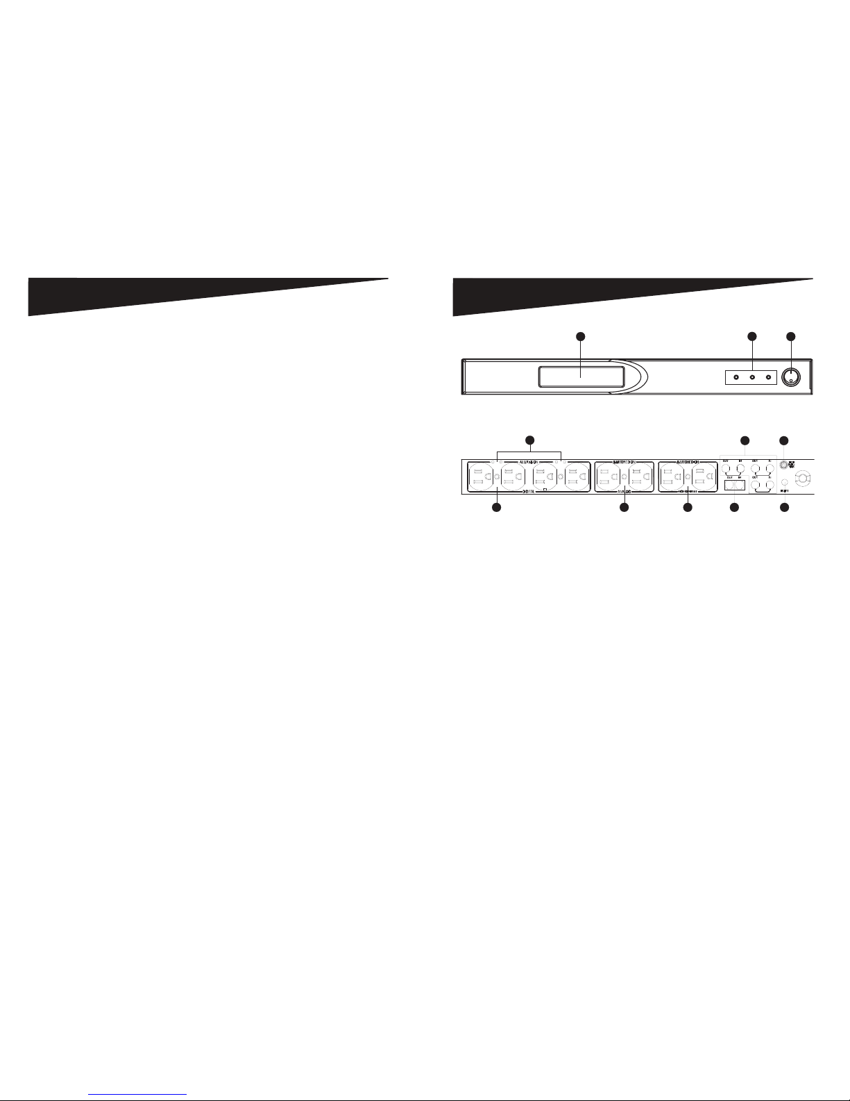
DESCRIPTIONS
1. On/O Power Push Buon – Turn power to the switched outlets on/o.
2. LCD Display – Monitor the Power Soluon’s main funcons.
3. LED Power Indicators – Monitor ground, protecon and switched power statuses.
4. Bank 1 Digital Filter – Connect digital components to reduce line noise and
interference.
5. Bank 2 Analog Filter – Connect analog components to reduce line noise and
interference.
6. Bank 3 High Current Filter – Connect audio components to reduce line noise and
interference.
7. Always On Indicator – Use the green indicators to determine when the switched
outlets are turned “on.”
8. DC IN – Control the Power Soluon using the remote trigger funcon of another
power management unit.
9. Telephone Line Input/Output – Protect your internal modem, TEL/FAX, or DSL
lines from power surges and spikes. Connect your modem, telephone line or fax
lines to these standard RJ11 phone jacks. The Power Soluon includes one IN
port and one OUT port.
10. DSS/Coax Line Input/Output – Protect coaxial cable lines from power surges and
spikes that can disturb and damage your equipment. Connect your cable TV,
satellite TV, antenna, HDTV, broadband or other coaxial cable lines.
11. 15-Amp Overload Resetable Circuit Breaker – Provides overload protecon with a
manually recoverable funcon.
1
3
2
Figure 2 - Front View Controls and Indicators
7
456911
8
10
Figure 3 - Rear View Controls
POWER SOLUTION 1000 Page 6Page 5 POWER SOLUTION 1000
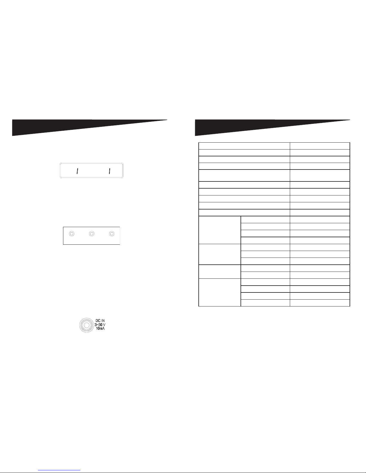
OPERATION
LCD Panel
The Power Soluon 1000 is equipped with an LCD Panel (Figure 4) that allows the user
to monitor input voltage and output current.
20
5
.
0
VOLTS CURRENT
Figure 4 - LCD Panel
• “VOLT” indicates the input voltage from the AC wall outlet.
• “AMPS” indicates the output current from the outlet banks.
LED Indicators
The LED indicators on the front panel (Figure 5) allow you to monitor important
power and safety informaon.
GROUNDED PROTECTED SWITCHED
POWER
Figure 5 - Front Panel LED Indicators
• “GROUNDED” indicates the status of the AC outlet. Green indicates that the AC
wall outlet is properly grounded.
• “PROTECTED” indicates the status of the Power Soluon surge protecon. Orange
indicates that the surge protecon is turned on.
• “SWITCHED POWER” indicates whether the “Switched” outlets are ON or OFF.
Remote Trigger Operation
This power soluon can be controlled remotely by another power soluon equipped
with a remote trigger out feature. To use remote trigger control, connect the remote
DC cable from the “DC OUT” connecon on the power soluon equipped with remote
trigger out to the “DC IN” connecon (Figure 6) on the Power Soluon 1000.
Figure 6 - DC IN Connecon
SPECIFICATIONS
Width 482.6mm
Height 44mm
Length 220.1mm
Weight 3.5kgs
Power Cord 14 AWG with 36 degree angle
(8 Feet)
Electrical Rang 120V/15A
Clamping Voltage L-N 400V, L-G 500V, N-G 500V
Surge Energy Joule Rang 2160J
Maximum Peak Spike Current 144000A
Maximum Spike Voltage 6KV
EMI/RFI Noise Filter X2 Capacitor (uF) 1.0uF*1; 0.22uF*1
Coil (T) 1mH*1
Frequency (KHz) 150KHz~100MHz
Aenuaon (dB) up to 65dB
DC Trigger Input Jack ψ 3.5
Voltage 3~30V
Current Requirement 10mA
Tel/Fax/Modem Energy (Joules) 160J
Let Through Voltage (V) <40V
DSS/COAX Cable
Protecon
Surge Arrestor Gas Tube
Breakdown Voltage <75V
Inseron Loss @10MHz <0.1dB
RF Connectors 3 Pairs, Gold nish
NOTE: Specicaons subject to change without noce.
This manual suits for next models
1
Table of contents
Popular Power Supply manuals by other brands


JFA Electronicos
JFA Electronicos BOB STORM instruction manual

Dometic
Dometic RAPS12R-U2 Installation and operating instructions

IBM
IBM CS821 Service manual

Allen-Bradley
Allen-Bradley FLEX Ex 1797-PS2E2 installation instructions

Altronix
Altronix AL400X220 Series installation guide

Hughes
Hughes Direcway DW6000 installation guide

Allen-Bradley
Allen-Bradley SLC 500 installation instructions

LEGRAND
LEGRAND E49 quick start guide

Puls
Puls QT40 Series instruction manual

PCB Piezotronics
PCB Piezotronics 8120-110A Installation and operating manual

Spellman
Spellman PTV Series instruction manual

Allen-Bradley
Allen-Bradley PowerFlex 700 AFE Migration guide