Audio Solutions TVAMSBAR3.1-35 User manual
Television Wall Mount with Integrated 3.1 Sound System with
Dolby Digital Technology
03/01/2014
Model Number TVAMSBAR3.1-35
Manufactured under license from Dolby Laboratories. Dolby and the double-D
symbol are trademarks of Dolby Laboratories.


3
TABLE OF CONTENTS
Safety Instructions ........................................................................................................................ 4
Getting Started............................................................................................................................... 6
Installation...................................................................................................................................... 8
Inputs and Controls..................................................................................................................... 21
Remote Control............................................................................................................................ 22
Remote Control LED/Sensor Location .................................................................................... 22
Remote Control Precautions ................................................................................................... 22
Remote Control (Learning)......................................................................................................... 23
Operation...................................................................................................................................... 24
LED Indicators......................................................................................................................... 24
Power On/Off........................................................................................................................... 24
Audio Input Source.................................................................................................................. 24
Hearing Impaired Mode........................................................................................................... 24
Volume Control/Mute............................................................................................................... 25
Audio Settings ......................................................................................................................... 25
Push Button Reset .................................................................................................................. 25
Menu Functions........................................................................................................................... 26
Accessing the Menu ................................................................................................................ 26
Speaker Volume Adjustment (Left, Right, Center, Subwoofer)................................................ 26
Speaker Expansion (On/Off) ................................................................................................... 26
Center Fill (On/Off) .................................................................................................................. 26
Flat (On/Off)............................................................................................................................. 27
Sound Field Selection ............................................................................................................. 27
Factory Reset .......................................................................................................................... 27
Software Version ..................................................................................................................... 27
Accessories ................................................................................................................................. 28
Maintenance................................................................................................................................. 30
Troubleshooting .......................................................................................................................... 31
Compliance .................................................................................................................................. 32
Features and Specications....................................................................................................... 33
Limited Warranty ......................................................................................................................... 34

4
Please read this enre manual carefully before
mounng the system to avoid bodily injury and/or
any property loss. If you do not understand these
direcons, or have any doubts about the safety of
the installaon, please call a qualied contractor
or contact the Audio Soluons™ customer
service department. Please check carefully to
ensure there are no missing or defecve parts.
Our customer representaves can quickly assist
you with installaon quesons and missing or
defecve parts. Replacement parts for products
purchased through authorized dealers will be
shipped to you directly. Do not aempt to use any
parts not provided by the manufacturer. Using
other screws could cause injury or property loss.
Never use defecve parts, as improper installaon
may cause damage or serious injury. Do not
use this product for any purpose not explicitly
specied by Audio Soluons™. Audio Soluons™
cannot be liable for damage or injury caused
by incorrect mounng, incorrect assembly, or
incorrect use.
• Read these instrucons – All the safety and
operang instrucons should be read before
this product is operated.
• Keep these instrucons – The safety and
operang instrucons should be retained for
future reference.
• Heed all warnings – All warnings on the
appliance and in the operang instrucons
should be adhered to.
• Follow all instrucons – All operang and
use instrucons should be followed.
• NeveraempttoinstalltheAudioMount™
^ŽƵŶĚďĂƌ^LJƐƚĞŵinahollowwall.
• Do not use this apparatus near water – The
appliance should not be used near water or
moisture –for example, in a wet basement
or near a swimming pool, and the like.
• Clean only with a dry cloth.
• Do not block any venlaon openings. Slots
and openings in the TV Audio Mount™ Soundbar
System are required for proper venlaon. Please
ensure that these openings are not blocked and
that no items are placed inside the
slots. Blocking the venlaon openings may
cause the system to overheat, which may
result in injury or property loss.
• Do not install near any heat sources such
as radiators, heat registers, stoves, or
other apparatus (including ampliers) that
produce heat.
• Do not defeat the safety purpose of the
polarized or grounding plug. A polarized
plug has two blades with one wider than
the other. A grounding plug has two blades
and a third grounding prong. The wide
blade or the third prong is provided for
your safety. If the provided plug does not t
into your outlet, consult an electrician for
replacement of the obsolete outlet.
• Protect the power cord from being walked
on or pinched parcularly at the plugs,
convenience receptacles, and at the point
where they exit from the apparatus.
• When the system is connected to a power
outlet, the power is always owing into the
system. To totally disconnect power you
must unplug the power cord.
• Only use aachments/accessories specied
by the manufacturer.
• Use only with the cart, stand, tripod,
bracket, or table
specied by the
manufacturer, or sold
with the apparatus.
When a cart or rack
is used, use cauon
when moving the cart/
apparatus combinaon
to avoid injury from p-over.
• Unplug the apparatus during lightning
storms or when unused for long periods of
me.
• Please keep the unit in a well-venlated
environment.
SAFETY INSTRUCTIONS

5
• WARNING: To reduce the risk of re or
electric shock, do not expose this apparatus
to rain or moisture. The apparatus shall not
be exposed to dripping or splashing and that
objects lled with liquids, such as vases,
shall not be placed on apparatus.
• WARNING: The wall socket plug is used as
disconnect device, the disconnect device
shall remain readily operable.
• This lightning ash with arrowhead
symbol within an equilateral triangle
is intended to alert the user to the
presence of non-insulated “dangerous
voltage” within the product’s
enclosure that may be of sucient
magnitude to constute a risk of
electric shock.
• The exclamaon point within an
equilateral triangle is intended to
alert the user to the presence of
important operang and maintenance
instrucons in the literature
accompanying the appliance.
• WARNING: To reduce the risk of electric
shock, do not remove cover (or back) as
there are no user-serviceable parts inside.
Refer servicing to qualied personnel.
• The apparatus should be connected to
an electrical wall outlet with a protecve
grounding connecon.
• Always replace a fuse with the same value
as the original fuse.
• Do not overload your extension cords or
power strips, as this can result in an electric
shock or re.
• Do not aempt to service or repair your TV
Audio Mount™ Soundbar System yourself.
Opening the cover will expose you to high
voltages and other hazards. Servicing is
required when the apparatus is damaged
in any way, such as power supply cord or plug
is damaged, liquid has been spilled or objects
have fallen into the apparatus has been
exposed to rain or moisture, does not
operate normally, or has been dropped.
If repair is required, please contact your
dealer or refer to a qualied service person.
• Do not install your TV Audio Mount™ Soundbar
System in an area subject to outside elements,
snow, moisture or high humidity. This device is
designed for indoor use only.
• If any of the following occurs, please contact
Audio Soluons™.
◦The system is exposed to rain or other
moisture.
◦The power cord is frayed.
◦The system is dropped or is damaged
in any way.
SAFETY INSTRUCTIONS

6
Introduction
Congratulaons on the purchase of your new Audio Soluons™ 3.1 TV Audio Mount™ Soundbar System. For
maximum benet, please read the enre manual before beginning installaon and operaon. With proper
usage, you will experience many years of high quality audio sound from your system.
Please register your TV Audio Mount™ Soundbar System at the following address: www.audiosoluons.com
Have your serial number and date of purchase available before you aempt to register.
For future reference, write the serial number found on the TV Audio Soluons™ Soundbar System, as well
as the purchase date, in the spaces provided below.
SN# _____________________________________
Purchase Date _____________________________
Opening the Package
The TV Audio Mount™ Soundbar System and its accompanying accessories have been carefully packed in a carton
designed to protect it from transportaon damage. Aer opening the carton, check that your system is in good
condion and that all listed contents are included.
Save the carton and packing material for future shipping.
Package Contents
• 3.1 TV Audio Mount™ Soundbar System
• Power Cord
• Remote Control
• Two AAA Baeries
• Cardboard Mounng Template
• Allen Wrench
• Mounng/Assembly Hardware
• This User Manual
Mounting Instructions
Please read all enclosed instrucons and verify hardware contents carefully before mounng.
GETTING STARTED

7
Wall Plate Mounting Hardware
#PartImage Descripon Qty
1Hex Head Lag
Bolt
6
2Plasc Insert 6
3 M8 Washer 6
TV Bracket Assembly Hardware
#PartImage Descripon Qty
A M4 x 12 Bolt 4
BM5 x 12 Bolt 4
C M6 x 12 Bolt 4
DM8 x 16 Bolt 4
EM4 x 30 Bolt 4
FM5 x 30 Bolt 4
GM6 x 35 Bolt 4
HM8 x 40 Bolt 4
IM4/M5
Spacer
4
JM8/M6
Spacer
4
KM4/M5
Washer
4
GETTING STARTED
#PartImage Descripon Qty
LM6/M8
Washer
4
M M4 Washer 4
NM5 Washer 4
OM6 Washer 4
PM8 Washer 4
Q5x5mm Allen
Wrench
1
RCardboard
Template
1

8
STEP 1
Read and understand all of the enclosed instrucons and verify that all parts are present and appear in
good working order before you begin.
NOTE: You will need at least 2 people to nish this mounng procedure. To avoid possible injury, do not
aempt to mount the TV alone.
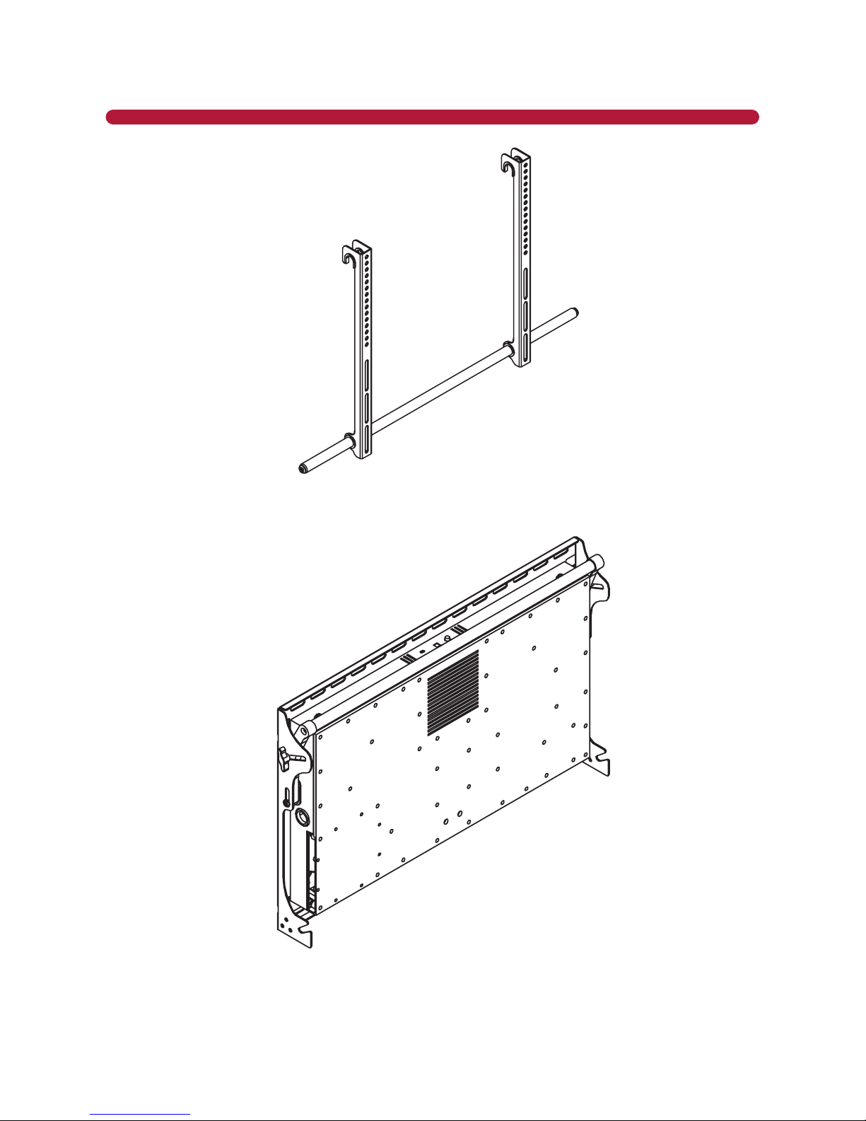
STEP 2
Use the supplied Allen wrench to loosen the socket screws (A) on each side of the lower pole (Figure 1).
You can then separate the unit into two parts: the TV bracket connecon (Figure 2) and the system wall
plate (Figure 3).
A
A
Figure 1 - Separate the TV Bracket and Wall Plate
INSTALLATION
9
Figure 2 - TV Bracket Connection
Figure 3 - Sound System Wall Plate
INSTALLATION
10
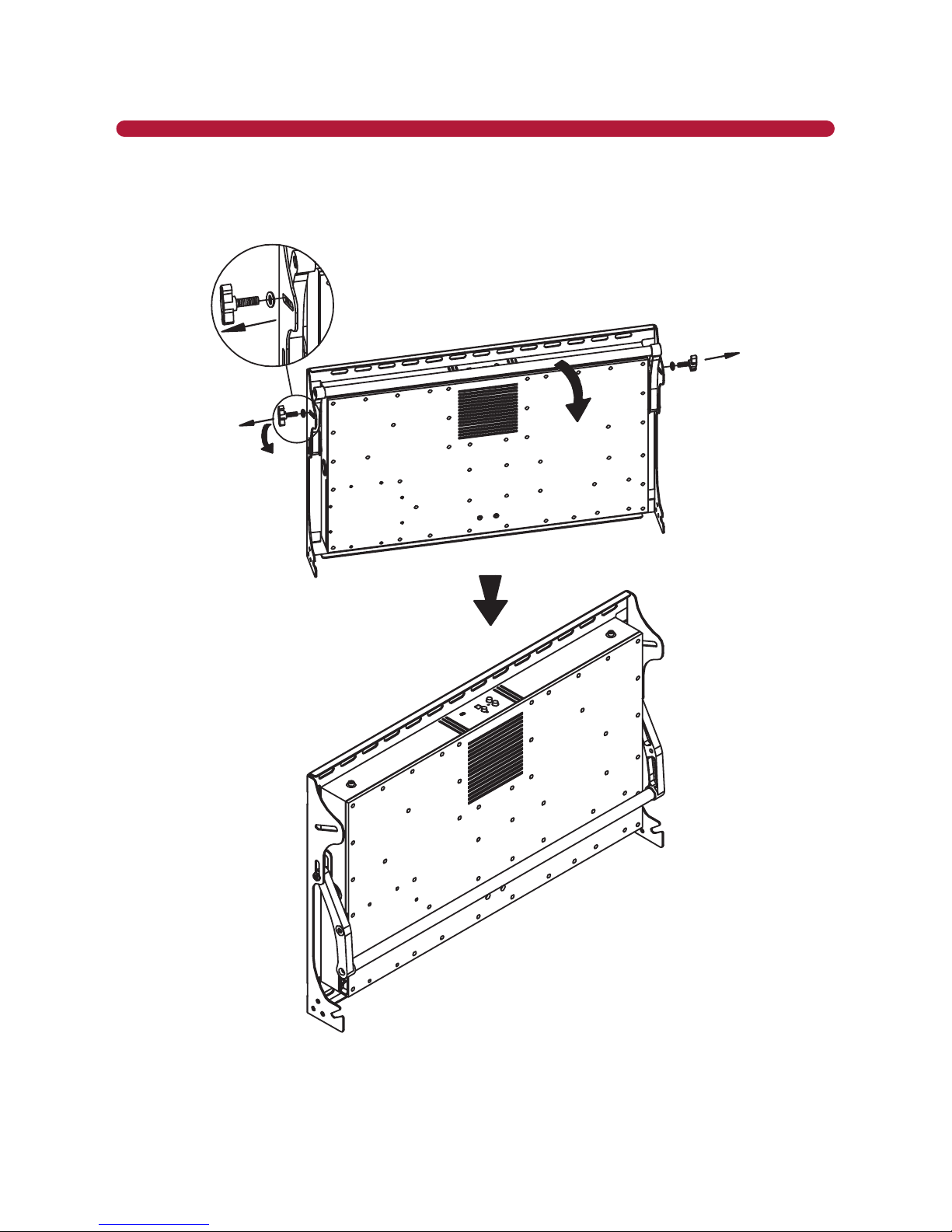
STEP 3
Remove the two T-screw handles (D) (Figure 4). Rotate the pole assembly downward to gain clear access to
the top mounng holes.
Figure 4 - Remove Handles
INSTALLATION

11
STEP 4
Place the cardboard template on the wall where you want to mount the system. Mark the center point on
the wall.
NOTE: Be sure to choose a wall area that is strong enough to support the combined weight of the TV
and Audio Mount™ Soundbar System. The locaon should be safe from hazards such as water or crushable
items. Do NOT ATTEMPT TO BOLT THIS UNIT TO THE HOLLOW PORTION OF THE WALL!
Wall with Studs
The Wall Plate must be mounted, at the top and boom, to at least 2 wooden studs, spaced a minimum
of 16” apart. Use a stud nder to locate the studs, then mark each stud. Place the template center to the
marked stud locaons. Make sure the template is level, then use masking tape to secure the template to
the wall. Mark inside holes in the template that correspond with the alignment of the studs in four places
(two top and two boom). Aer making clear marks for the holes, remove the template. Using a 3/16” drill
bit, pre-drill a 2.5” deep hole in each marked locaon.
Concrete Wall
Choose a solid wall area (avoid hollow walls or the joint of the bricks). Make sure the template is level, then
use masking tape to secure the template to the wall. Mark inside holes in the template in four places (two
top and two boom). Using a 3/8” masonry drill bit, pre-drill a 2.5” deep hole in each marked locaon.
Figure 5 - Use Mounting Template and Pre-Drill
INSTALLATION

12
STEP 5
Aach the Wall Plate to the wall.
Wood Stud Mounting
Line the TV Audio Mount™ Soundbar System bracket up with the predrilled holes and aach the Wall Plate
to the wall using the included square head screws and M8 washers.
Concrete Wall Mounting
Insert the plasc sinkers into the predrilled holes and tap securely into the hole. Aach the Wall Plate to
the wall using the included concrete bolts (Figure 6).
Figure 6 - Concrete Wall Mounting
WARNING: Use only the supplied screws intended for the selected applicaon to avoid personal injury or
property damage.
INSTALLATION

13
WARNING: DO NOT ATTEMPT TO MOUNT THIS UNIT TO A HOLLOW WALL WITHOUT BOLTING INTO
STUDS!
Hollow Wall or Decorative Cardboard
NO!
Figure 7 - Hollow Wall WARNING!
INSTALLATION

14
STEP 6
Aach the TV to the TV Bracket Connecon (Figure 8).
a. Remove the round tube (B) from the TV Bracket Connecon.
b. Choose the correct screws (the ones that work with your TV) from the supplied hardware bag to at-
tach the two brackets (C) to the back of the TV. Make sure the brackets are posioned with the tube
hole at the boom of the TV.
c. Once the brackets are connected, slide the round tube (B) back into the TV brackets.
Option 1:
Option 2:
Figure 8 - Attach TV to Bracket
NOTE: Please use the correct screws and washers for the holes on the TV back. Assembling with incorrect
screws and washers will damage the holes on the back of the TV. Some TVs without a at back may
require the use of spacers when aaching the brackets. Make sure the two TV brackets are even and
that they’re using the same mounng holes on the bracket. Uneven assembly will cause the TV screen to
slant.
INSTALLATION

15
NOTE: You will need at least 2 people to nish this mounng procedure. To avoid possible injury, do not
aempt to mount the TV alone.
NO!YES!
STEP 7
Li the upper pole and screw it back into place using the two T-screw handles (D) (Figure 9).
Figure 9 - Replace Upper Pole
INSTALLATION
16
STEP 8A (LCR Speaker Position Adjustment)
Figure 10 - LCR Speaker Position Adjustment
INSTALLATION

17
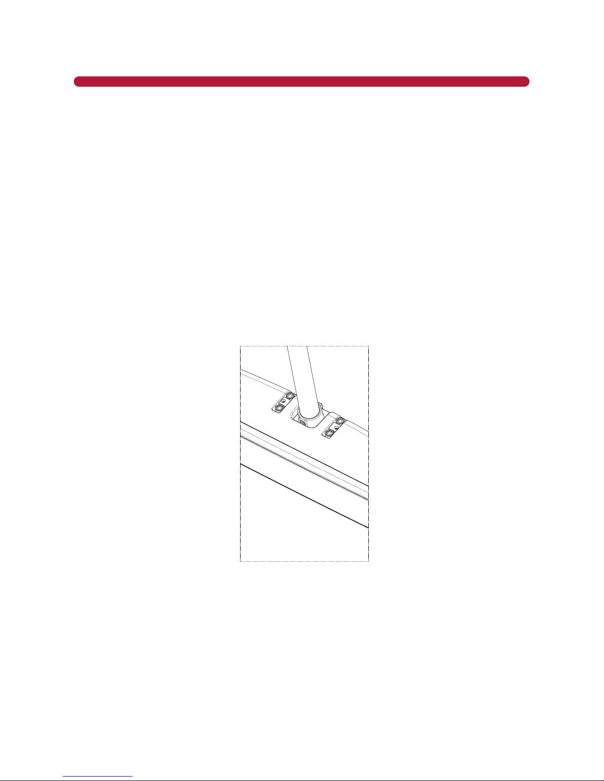
STEP 8B (Center Speaker Pole Adjustment)
Located at the boom center front of the TV Audio Mount™ Soundbar System are two adjustment screws
for the centerspeaker. Once you have aached the brackets to the back of the television in STEP 6,
perform the following steps to adjust the boom speaker, as necessary.
Figure 11 - Measure Height
Figure 12 - Adjust Center Pole
Measure the distance from the top of
the mounng hook to the boom of
the TV, as shown in Figure 11.
b. Add 1 inch to the measurement you
took in the above step 1 to obtain the
proper adjustment height.
c. Loosen the two center pole locking
screws. Do not remove screws.
d. Move the center speaker by sliding the
boom pole unl the distance from
the top support bar to the top of the
center speaker corresponds with the
required adjustment height. Do not
let go of the boom speaker while
adjusng.
e. Tighten the two center pole locking
screws, as shown in Figure 12.
Measurefromtopof
hooktoboomofTV.
INSTALLATION
CenterPoleLockingScrews
.

18
STEP 9
Hang TV and adjust speaker.
a. Hang the pre-assembled TV unit on the upper pole.
b. Clip the screws (A) into the lower channel of the Wall Plate and ghten on both sides (Figure 11).
Figure 13 - Attach TV Mount to Wall Mount
INSTALLATION

19
STEP 10
Connect the audio cables from your television to the TV Audio Mount™ Soundbar System.
The TV Audio Mount™ Soundbar System has four ways to input the audio from your TV.
• Line Level Out is located on your TV panel in the Audio Out secon. It will have two connectors
marked L (Le-White) and R (Right-Red).
• A 3.5mm Head Phone Jack is located on most TV panels in the Audio Out secon. Only use this
connecon if your TV does not have an Opcal or Coaxial connecon. When using this connecon,
you must set the volume of your TV to a level that will allow your TV Audio Mount™ Soundbar System
to detect audio. This is explained in more detail in the “TV Sengs” secon.
• Opcal output is located on most TV panels in the Audio Out secon. Look for a square connector
marked Opcal or S/PDIF.
• Coaxial output is located on your TV panel in the Audio Out secon.
Audio inputs for the TV Audio Mount™ Soundbar System are shown in Figure 14.
Figure 14 - Audio Input Options
Before connecng the TV to the TV Audio Mount™ Soundbar System, lower the TV volume to zero or use the
TV menu to turn your TV speakers OFF.
Decide which inputs to use and connect the appropriate cable from your TV Audio Out to the connector on
the TV Audio Mount™ Soundbar System.
You will now control the volume of your system with the TV Audio Mount™ Soundbar System remote controller
supplied with your system. If you have a learning remote controller, you can program it to replace the
remote controller supplied with the TV Audio Mount™ Soundbar System.
INSTALLATION
20
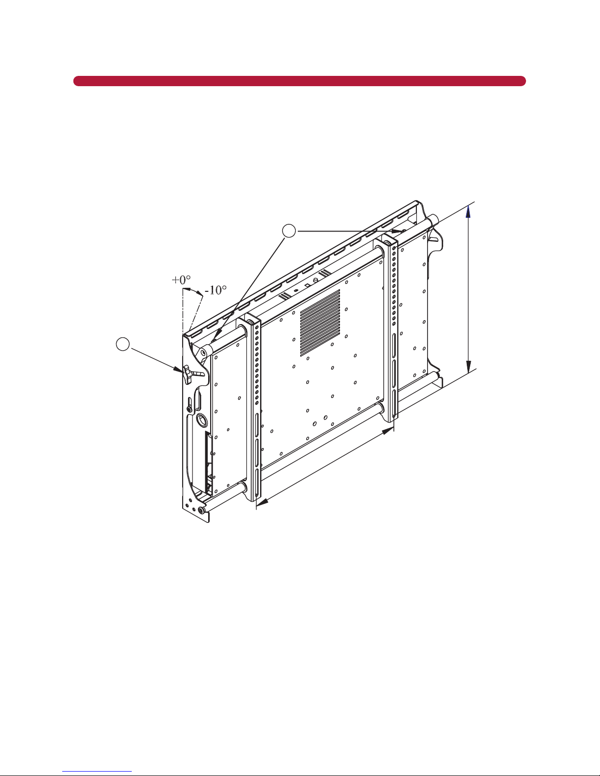
STEP 11
Adjust the angle of the TV and then ghten the T-screw handles (D) and locking screws (A) (Figure 15). You
can then adjust the width and angle of the speakers and lock the speaker screws, as described in Step 8.
NOTE: Arrange your cables to avoid the lt adjustment area. When arranging the cables, please leave
sucient slack for future angle adjustments.
A
D
Max 600mm
Max600mm
Figure 15 - Adjust Angle
INSTALLATION
Table of contents


