manuals.online logo
Brands
  1. Home
  2. •
  3. Brands
  4. •
  5. AUDIO TELEX
  6. •
  7. Amplifier
  8. •
  9. AUDIO TELEX AT120R User manual

AUDIO TELEX AT120R User manual

AMtilDilril@ ti
m
co M lvt u N I cATl o N sPrY LrD
g
o
-
a
tr
c
-
o
=
l-
(u
l-
o
AT12OR
Receiver Amplifier
&
ATl2ORC
Receiver Cassette Ampl ifier
A3
Od t
El&rrd
g
Audio Telex Communications Pty Ltd
ACN 001345482 lncorporat€d ln NSW
NSW & ACT QLD & NT
1 49 Beaconsfleld Stre€t
Prlvate Bag 149
Slherwater NSW 2128
Australla
Ph 02 9647 1411
Fax 02 9648 3698
42 Commerclal Road
PO Box 871
Fortltude Vall€y QLD 4006
Ph 07 3852 1312
Fax Ol 32521237
2U 27 7 ]llddleborou gh Road
Box HllMc 3128
PO Box 151
Blackbum South VIC 3130
Ph 03 9890 7477
Fax 03 9890 7977
7164-66 K€nt Street
PO Box 489
Cannlngton WA 6107
Ph 08 9356 2761
Fax 08 9356 2762
Electronic Concepts Pty Ltd
76 George Street
Thebarton SA 5031
PO Box 7034 Hutt Street
Adelelde SA 5000
Ph 08 8234 9411
Fax 08 8234 9441
K W tlcculloch Pty Ltd
' 5lla Albert Road
lf,oonah TAS 7009
Ph 03 6228 6373
Fax 03 6278 '1063
NewZealand
Unlt B, 'l l Plermark Orlve
PO 8ox 5'12
Albany Nz 1331
Ph 09 415 9426
Fax 09 415 9864
AT120R-1 Receiver Amplifier
ATI 20RC-l Receiver/Cassette Amplifier
Product Description
The ATl20R-l is a 120 watt, 4 channel (dual mic/line) mixer amplifier that has been optioned with ur AIvl/FM radio receiver.
Sfunilarly, the ATl2oRC-l is optioned with an Alvl/FM radio receiver and cass€tte player. The AT120R-I and ATl20RC-l o,p€rate
from 240 VAC, 50 tIz (or 110 VAC with hctory modification) and may be desk or rack mounted (via an optional rack mount kit).
Both the AT120R-1 and AT120RC-1 will deliver 120 watts into loads of4 or 8 obms, 70 m 100 volt line. Both amplifiers include a
6 zone, 100 volt line spea.ker zone select f$tur€ cmplete with all-call. The maximum recornmended load of the ATt20R-l and
ATI20RC-1 on the 100 volt line output is 80 ohms.
Front Panel Controls
Dual ilicrophonerline Gain: fne 4 dual midline input controls are labelled chl .... Ch4 and should be adjusted to
provide the required mix level for each individual channel. Start with the conhols set to Level 0 and turn the controls clockwise
until the desired mix level for each channel is reached.
Bass Tonal Control: Setting this control in the c€ntre position will give an overall flat bass response to the output of the
amplifier. Adjusting the bass control in a clockwise direction will provide up to 12 dB of bass boost @ lW Hz. Adjustin! the bass
control in a count€r-clockwise direction will provide up to 12 dB ofbass cut @ 100 IIz.
Treble Tonal Control: Setting this control in the cenne position will give an overall flat h€ble response to the output of the
amplifier. Adjusting the treble c.onhol in a clockwise direclion will provide up to l0 dB of aeble boost @ l}K Ih. Adjusting the
treble control in a counter-clockwise direction will provide up to l0 dB ofheble cut @ lOK liz.
llaster Output This confiols the ov€rall output l€vel ofthe amplifio depending or the levels set for the individual inpgt mix
channels as detailed above. Start with the control set to Leyel 0 and turn clockwise until the desired output level of the amilifier is
reached
All Call Button: When pressed this grey button will connect the 100 volt output of the amplifier ro all 6 of the switched
outputs of the amplifier. Depressing this button again will disconnect the switched output. This switch is push-on, push-off and is
nm int€docking.
Speaker Selector: These 6 black buttons are for switching the 100 volt line output of the amplifier to any combination of
the 6 available speaker zmes. The switches are push-on, push-off and are non int€docking (both with cach other and with the all-
call button). The maximum capacity of each speaker zone is 60 watts so care should be taken to ensure that no individual zones is
loaded dovn for more than 60 watts, alwals remembering that the total amplifier load is 120 watts. It is possible to safely have one
zone set for 60 watts and the other 5 zones s€t for 12 watts for o(ample.
Limit Led: This red led is designed to give the user an indication of the operating conditior of the amplifier urd is integral to
the inbuilt proteclion included in the amplifier. This led will glow red ifthe amplifer is o,perating into an q(cessive lood or if one or
more ofthe input channels is zupplying an unacceptably high level of signal. It is nonnal for this ledto flicker ol and offhowever, if
it glows steady, the amplifier will shut dorvn for a period of approximately 3 seconds and continue to cycle in this frshion until the
abnormal condition is removed-
Evac BU$On: When pressed, this orangg push-on, push-off button will activate the inbuilt evacuation tone gencrator. when
the tone is acti te4 input channels 3 & 4 are muted wiile input channels I & 2 remain active in case an em€rg€ncy message is
required.
Bell Button: When pressed this black, push-or, push-offbutton will activate the inbuilt bell tone generator. When the tone is
activate4 inputs 3 & 4 are muted while inputs I & 2 remain active.
POWef Button: This switch contols the switching of AC power to the amplifier. Rocking this switch upwards tums on AC
power to the amplifier while rocking the switch downwards hrns pow€f, offto the amplifier. When in the upward on position, the
red neon in the body ofthe switch will gtow.
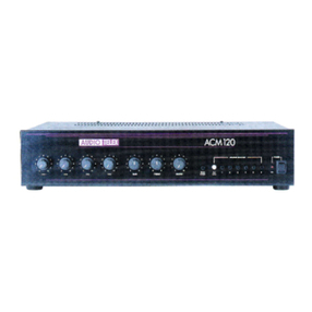
AmrFm Recelver: The receiver includes a gain control which ap€rates identically to the midline gain controls described on
the previous page (although it is cmpl€tely indep€ndent of the controls describ€d above). The gain coahol incorpdated in to the
receiver controls the input level to the amplifi€r for both the receiver and the cass€tte player (if installed). When installed and
activated, the cassette player will override the receiver so that only one ofthe receiver or cassette player may b€ operat€d at once, the
cassette play€r haying priority.
You may monitor the output of the rec€iver via an intemal monitor speaker. The volume ofthe monitor speaker is contolled by
the vertical slider contol labelled Monitor, located cenhally on the fiont panel ofthe amplifi€r. Ifyou \mnt to preview the output of
the receiver before sending it out live to the sp€akers, simply turn the amplifiers master output level control fiIly anti-clockwise to
turn offthe output ofthe amplifier. Note that ifyou do this, all output is tumed ofi, including all micophone inputs.
Five hming bands are availablg 2 x AM and 3 x FM: the receivers display panel will illuminate to display the relevant
information. To select the desired band press the button marked Alv{/FM. Each time this button is pressed a different tuning band
will be indicated on the display panel. Up to 30 preset channels may be stor€4 6 for each tuning band. To store a channel operate
the up and down arrow buttons tmtil you locate and are properly tuned to the radio station of your choice. Then, press the memory
button which will cause the channel to flash on the display panel. Press the desired storage channel (numbered i to Oy. the radio
station chos€n is th€n stored in that mernory location. You may autornatically search for radio statiom by op€rating the up and down
arrow buttons. The receiver will search fc and automatically lock on to threshold signals in the frequency band you have selected.
Continue to press the up or donm arrow buttons to resume your s€arch or to fine tune any station selected.
Cassette Player (AT120RC-1 Only): me cassette player has 3 mique controls, one each for Eject, Rewind (REw)
and Fast Forward @F). In addition, there is a gain contol located on the receiver module that controls the output level of the
cassette deck (and, when a cassette is insertod has pricity over the receiver as detailed above). The cassettJ phyer may be
mmitored and preyiewed in exactly the same fashion as the receiver.
The cassette playef will tregin playing imnediately a cass€tte is ins€fted though the slot in front ofthe cassette play€r. The REW
and FF buttons will shuttle the cassette backwards or forwards respectively. Pressing both the REW and FF buttors together will
reverse the playing direction of the cassette player and effectively change the side of the cassette bcing played. Pressing the eject
button will eject the cass€1te and switch back to the receivers output. Ifyou do not want to switch inmediately back to thi receivers
output when you eject the cassefte, make sure that the gain conhol on the receiver is turned fully munter clockwise.
Optional Accessorles
E The instrllrtion of some ofthe following optional rccessorics involves scc$s to tbc insidc of thc rmplificr. Inste[etion
should only be tttemptcd by a qurlified techniciln. A.lways turn ofi thc AC power lnd remove the AC power cord bcfore
tttempting to lccess thc inside of the rmpllficr, Pless€ conbct your ne.rest Andlo Tclcr ofncc for detrils of your nerrest
quelified technicirn.
TX3010 Vox tutlng ltodule. Wherr installed (as per the comprehensive instructions supplied with the TX3010),
channels I & 2 of the amplifier will mute channels 3 & 4 ofthe amplifier. The receiver and cass€tte player inputs will also be
muted.
ATR KBLK. 19" rack mount kit
Please see ovsr for rear panel connection details 3
Rear Panel Connections
1.9 I !l I c
, Lr lr l
@@@@
l. 3 Pin IEC AC tains Power lnlet rhe operating voltage is 240 VAC @ 50 llz t I l0 vAc @ 60 Hz. The AC
power voltage level is not ext€rnally us€r adjustable but is frctcy pre-set. The inl€t is equipped widr an inbuilt AC fuse holder
fittd with a 4 Anp fuse plus a spare. Power consumption is 225 YA. t Pbasc ensurc thlt the mths powcr cord is
disconnccted bcfore rttcmpting to check or rephce this fusc.
DlfeCt OUtpUt COnneCUOnS. Th€s€ screw terminals allow access lo the direct outputs of the amplifier and allow for
the swirching ofthe various tmes available. Reading frm left to right the terminals are:
Low Impedance Common
4 Ohms
8 Ohms
Costant Voltage Commdr
70 Volt Line
100 Volt Line
Spare
Bell +
Evacuatim +
Alert +
Pre Annotmce +
Tone Generatc Common (note that only one tme may be activated at a time)
Switched OUtpUtS. feaaing from t€ft to right these screw terminal pairs ccrespod to the switched 1@ volt line outputs
6 .... 1 as indicated m the front panel of the arnplifier. For each pair, the left hand terminal is the cmmm and the right hand
terminal is the 100 volt ontput.
Receiver Antenna Connection. As described above, the receiver can tune to both the AM and FM bands. The FM
band has dual 75 and 300 ohn impedance capability. For best FM r€sults, we recommend using the 75 ohm cornectiqr to a
rermote antenna via 75 olun cnaxial cable.
Tape Output This is a monaural RCA type connector and witl provide an output of 350 mv in to a loK ohm load. This
output is sourced befor€ the mastei gain contol and as such, the tape output level is not influenced by the operation ofthe master
gain control.
Active Balanced, XLR Sockets For The ticrophone lnputs. with an input sensitivity of 0.75mv @
200 ohms. Pin oqmcctims are: pin #l-earth; pin #2-active OiSh, +); pin #3-ac-tive ooq ). Phantom pow€r of +15 volts is
available on all microphone inputs. Reading frm left to right across the rear panel, the cannectim are for microphme inputs 4,
3,2,&lrespectively.
RCA Sockets For The onaural Line Level lnputs. Inputs #'s 1,2 & 3 have an input s€nsitivity of 75mv
@ 47K ohns. Input il4 has an input sensitivity of250 mV @ 47K ohms. Reading from left to right across the rear panel, the
connectiurs are fc inputs 4, 3, 2, & I respoctively.
3.
4.
5.
7.

This manual suits for next models

1

Other AUDIO TELEX Amplifier manuals

AUDIO TELEX SA120 User manual

AUDIO TELEX

AUDIO TELEX SA120 User manual

AUDIO TELEX PRO AUDIO TX300B User manual

AUDIO TELEX

AUDIO TELEX PRO AUDIO TX300B User manual

AUDIO TELEX ACM120 User manual

AUDIO TELEX

AUDIO TELEX ACM120 User manual

AUDIO TELEX SA120 - BROCHURE 2 User manual

AUDIO TELEX

AUDIO TELEX SA120 - BROCHURE 2 User manual

AUDIO TELEX ACM250P User manual

AUDIO TELEX

AUDIO TELEX ACM250P User manual

AUDIO TELEX 8842 User manual

AUDIO TELEX

AUDIO TELEX 8842 User manual

AUDIO TELEX SA120-1 User manual

AUDIO TELEX

AUDIO TELEX SA120-1 User manual

AUDIO TELEX 8182 B User manual

AUDIO TELEX

AUDIO TELEX 8182 B User manual

AUDIO TELEX IC30 User manual

AUDIO TELEX

AUDIO TELEX IC30 User manual

AUDIO TELEX ACM120 User manual

AUDIO TELEX

AUDIO TELEX ACM120 User manual

AUDIO TELEX ACM120R User manual

AUDIO TELEX

AUDIO TELEX ACM120R User manual

AUDIO TELEX AT120RC User guide

AUDIO TELEX

AUDIO TELEX AT120RC User guide

AUDIO TELEX AT120 User manual

AUDIO TELEX

AUDIO TELEX AT120 User manual

AUDIO TELEX DCM250 Operating and installation instructions

AUDIO TELEX

AUDIO TELEX DCM250 Operating and installation instructions

AUDIO TELEX ACM2151 User manual

AUDIO TELEX

AUDIO TELEX ACM2151 User manual

AUDIO TELEX SA60 User manual

AUDIO TELEX

AUDIO TELEX SA60 User manual

AUDIO TELEX AT250B User manual

AUDIO TELEX

AUDIO TELEX AT250B User manual

AUDIO TELEX ACM2150 User manual

AUDIO TELEX

AUDIO TELEX ACM2150 User manual

AUDIO TELEX AT120-3 User manual

AUDIO TELEX

AUDIO TELEX AT120-3 User manual

AUDIO TELEX SA250B User manual

AUDIO TELEX

AUDIO TELEX SA250B User manual

AUDIO TELEX SA120-4 User manual

AUDIO TELEX

AUDIO TELEX SA120-4 User manual

AUDIO TELEX ACM250P Operating and installation instructions

AUDIO TELEX

AUDIO TELEX ACM250P Operating and installation instructions

AUDIO TELEX DCM500 User manual

AUDIO TELEX

AUDIO TELEX DCM500 User manual

AUDIO TELEX SA120 User manual

AUDIO TELEX

AUDIO TELEX SA120 User manual

Popular Amplifier manuals by other brands

Camco D-POWER 4 user manual

Camco

Camco D-POWER 4 user manual

Elan D400 Installation manual and user's guide

Elan

Elan D400 Installation manual and user's guide

TECNARE MH-4000 owner's manual

TECNARE

TECNARE MH-4000 owner's manual

Crest Audio Ci 20 X 4 Specification sheet

Crest Audio

Crest Audio Ci 20 X 4 Specification sheet

Renegade REN1000S Mk3 user manual

Renegade

Renegade REN1000S Mk3 user manual

Pass Laboratories Pass Aleph 60 owner's manual

Pass Laboratories

Pass Laboratories Pass Aleph 60 owner's manual

LA Audio Electronic UB292 datasheet

LA Audio Electronic

LA Audio Electronic UB292 datasheet

Takstar E300W manual

Takstar

Takstar E300W manual

D.A.S. PA-500 user manual

D.A.S.

D.A.S. PA-500 user manual

EMP-Centauri P.140-M instruction manual

EMP-Centauri

EMP-Centauri P.140-M instruction manual

Precision Power Sedona 50Q owner's manual

Precision Power

Precision Power Sedona 50Q owner's manual

Pepperl+Fuchs SIL HiD282 Series manual

Pepperl+Fuchs

Pepperl+Fuchs SIL HiD282 Series manual

Kenwood KAC-8406 instruction manual

Kenwood

Kenwood KAC-8406 instruction manual

Behringer Ultracoustic ACX450 user manual

Behringer

Behringer Ultracoustic ACX450 user manual

J&M Corporation ROKKER XXR installation instructions

J&M Corporation

J&M Corporation ROKKER XXR installation instructions

Esoteric GRANDIOSO C1 owner's manual

Esoteric

Esoteric GRANDIOSO C1 owner's manual

Mackie FRS1700 Specifications

Mackie

Mackie FRS1700 Specifications

HBM CANHEAD operating manual

HBM

HBM CANHEAD operating manual

manuals.online logo
manuals.online logoBrands
  • About & Mission
  • Contact us
  • Privacy Policy
  • Terms and Conditions

Copyright 2025 Manuals.Online. All Rights Reserved.