manuals.online logo
Brands
  1. Home
  2. •
  3. Brands
  4. •
  5. AUDIO TELEX
  6. •
  7. Amplifier
  8. •
  9. AUDIO TELEX IC30 User manual

AUDIO TELEX IC30 User manual

AMrilDril@ fl{lll
c o M M u N I C AT I O N S P'rY LrD
www.audaotelex.com
lc30
Mixer Amplifier
3
adtu
En b.-a
Cor'Fdry
@ttat
Audio Telex Communications Pty Ltd
ACN 001345482 lncrporatad in NSW
NSW & ACT QLD & NT
'149 Beaconsfield Str€et
Private Bag 149
Silverwater NSW 2'128
Australia
Ph02964T 14,t.1
Fax 02 9648 3698
42 Commercial Road
PO Box 871
Fortitude Valley QLD rt006
PhoT 3A52't312
Fax 07 3252 1237
22127 7 lllddleborough Road
Box Hill VIC 3128
PO Box 151
Blackburn South VIC 3'130
Ph 03 9890 7477
Fax 03 9890 7977
299 Fitzgerald Street
West Perth WA 6005
PO Box 404
North Perth WA 6906
Phoa92284222
Fax 08 9228 4233
Electronic Concepts Pty Ltd
76 George Street
Thebarton SA 5031
PO Box 7034 Hutt Street
Adelaide SA 5000
Ph 08 8234 9444
Fax 08 8234 9441
K W itcculloch Pty Ltd
54e Albert Road
Moonah TAS 7009
Ph 03 6228 6373
Fax 03 6278 '1063
Unit B, 11 Piermark Drive
PO Box 512
Albany NZ 1331
Ph 09 415 9426
Fax 09 415 9864
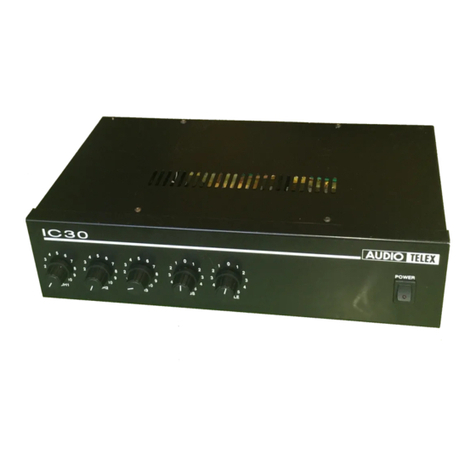
lC30 Mixer Amplifier
Product Description
The IC30 is a 30 watt mixer amplifier which operates on 240 VAC, 50 Hz (or I l0 VAC with factory modification) or 12 VDC via
an externa.l DC power supply source. The amplilier comes standard as desk mounted with rubber feet but can be rack mounted via
an optional rack mou-nt kit (IC3ORMK). The IC30 will deliver 30 \yatts into a load of .l ohms.7o or lO0 volt line. The IC30 may be
stacked to a ma\imum of four units high. An IEC 6'pe mains cord and receptacle is provided, the recepucle also houses the mains
fuse in a drawer which pulls open to expose the fuse. A single spare fuse is also located in this drawcr.
Front Pane! Controls
l. Dual Microphone/Line Gain Controlt The dual mic/line input conrrols are labelled Ch I through ro Ch 3 and
should be adjusted lo govide the required mix level for each individual channel. Start wilh the controls set to lcvel 0 and tum
the controls clockwise until the desired mix level for each channel is reached.
Bass Tonal Control: Setting this control in the centre position will give an overall flat bass response to the output of
the amplifier. Mjusting the bass control in a clockwise direction will provide up to l0 dB of bass boost @ IOO IIz. Adjusting
the bass control in a counter-clockwise direction will provide up to -10 dB ofbass cut @ 100 Hz.
Treble Tonal Control: Setting this control in the centre position will give an overall flat treble reslnnse to the output
of the amplifier. Adjusting the teble control in a clockwise direction will provide up to 9 dB of treble boost @ l}kJlz.
Adjusting the treble control in a counter-clockwise direction will provide up to -9 dB of treble cut @ lO kHz.
Power Button: This su/itch controls the switching of AC power to the amplifier. Rocking this switch upwards turns on
AC power to the amplifier while rocking the switch downwards tums porv.:r of to the amplilier. When in the upward position.
the red neon in the bodv of the witch will glow.
3.
4.
ICSO
iO;i
0r0
laUDTOTTrT
tr
liol i
0 r0
, , ,,\,
, i( ),
55
0 10 Blss
1(t
Rear Panel Connections
t. 3 Pin IEC llains Power lnlet: the operaring volrage is 240 vAC @50Hzot ll0 vAC @ 60 Hz. The AC power
voltage lcvel is not cxlemally user adjustable but is facrory pre-set at 240VAC. The inlct is equipped with an inbuilt AC fusc
holder fitted wilh a I amp fuse plus a s;nre. found within the holder. pou€r consumption is 50VA.
t Please ensure that the mains power cord is disconnected before attempting to ch€ck or r€place this fuse.
2. Direct Output Terminal Strip: rnese screw terminals allow access to rhe direct outpurs of the amplifier. Spnre
screw terminals allow for the conncction ofvarious tone module accessories. Reading from left to right the rerminals are-
o 12 Volts DC Positive (+) Power Connection
I 12 Volts DC Negative G) power Connection
' Spare
o Low Impedance Comrnon
o 4 Ohms
. Constant Voltage Common
. 70 Volts
o 100 Volts
o SPare
o Spare
. Remote Muting On/Off Connection *
+Charutels 2 and 3 are muted when these two terminals are shorted together onlv when the TX30l0 mute module is fitted.
Note: The minimum impedance at any lime on maximum load for 100 Volt line should be no less than 330 Ohms for the IC30.
3 Tape O utput: RCA style phono output connector for tine level output. Provides a maximum of 350mv into loK Ohms,
ideal for a connection to most standard ape recorden. This output is sourced before the master gain control and as such, the
tape output level is not inlluenced by the operation of the master gain control.
4 Univergal Microphone/Line lnputs: with an input sensirivity of l.5mv@ 200 ohms, pin connections for XLR
balanced microphone input connectors are: pin #l -earth; pin #2-active (high, +): pin #3-active (low, -). The RCA socket line
level input connectors havc an input sensitivit-y of 80mV @ 47K ohms. Reading from left to right actoss the rear lnnel- the
connection are for the inputs 3, 2, & I respectively. All three inputs can be used for microphone and autliary input sources. It
is also possible to connect both microphone and au\iliary inputs to one channel simultaneously. however their relative levels to
one another will be fixed, as there is one gain control for each channel on the front panel.
Optional Accessories
E The installation of sone of the following optional accessories involves access to the inside of the amplilier. Installrtion
should only be attempted by a qualified technician. Always turn off the AC power and remove the AC power cord before
dtempting to access the inside of the amplilier. Please contact your nearest Audio Telex ofFrce for details of your nearest
qualified technician,
Tone Generatorg: Four sepaftfe tones are available as an option via the ATC5488 tone generator board. This internally
mounted PCB is easily fitted and plugs directly into a socket provided on the internal circuit board PCB6I89. Please follow the
instructions supplied with the tone generator- When any tone from the ATC5488 is activated all inputs will automatically mute
except for input one.
Tones available on the ATC5488 tone genemtor board are:
Evacnation Tone (to Australian Slandard A52220.1.2)
Alen Tone (to Australian Standard AS2220.1.2)
Bell Tone
Pre Annoulce Chime
TX30l0 Vox iluting todule: When installed (as per the comprehensive instructions supplied with the Tx301o),
channel I ofthe amplifier will mute channels 2 & 3 ofthe amplifier.
lC30Rl{K: t9" rack mount kir
Fuse Sizes
llains 240 VAC: t Ampere Slow Blow
Notes
The DC ftse is locat€d on the circuit board. This is a feature of the IC series amplifren, which is equipped with a current Umiting
circuit prwenting excessive DC c'urrents, thus eliminaring the risk of blowing high tension fixes. In the unlikely event that the DC
fuse actuat€s, the outtrrt IC's should be checked, as it is probable that the amplifier has been subjected to very extreme conditions.

Other manuals for IC30

2

Other AUDIO TELEX Amplifier manuals

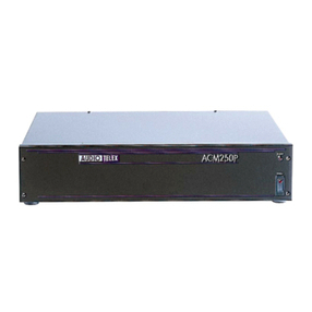
AUDIO TELEX ACM250P User manual

AUDIO TELEX

AUDIO TELEX ACM250P User manual
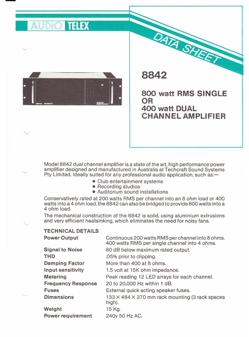
AUDIO TELEX 8842 User manual

AUDIO TELEX

AUDIO TELEX 8842 User manual
AUDIO TELEX DCM500 User manual

AUDIO TELEX

AUDIO TELEX DCM500 User manual
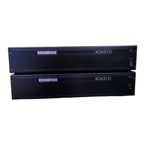
AUDIO TELEX ACM2151 User manual

AUDIO TELEX

AUDIO TELEX ACM2151 User manual
AUDIO TELEX ACM120 User manual

AUDIO TELEX

AUDIO TELEX ACM120 User manual
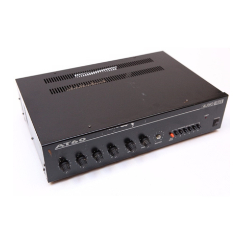
AUDIO TELEX AT User manual

AUDIO TELEX

AUDIO TELEX AT User manual
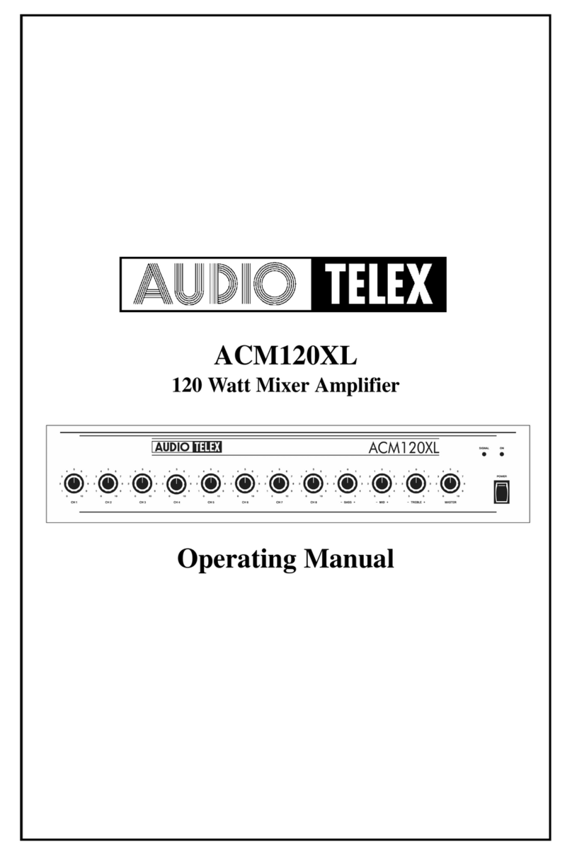
AUDIO TELEX ACM120XL User manual

AUDIO TELEX

AUDIO TELEX ACM120XL User manual

AUDIO TELEX AT120-3 User manual

AUDIO TELEX

AUDIO TELEX AT120-3 User manual
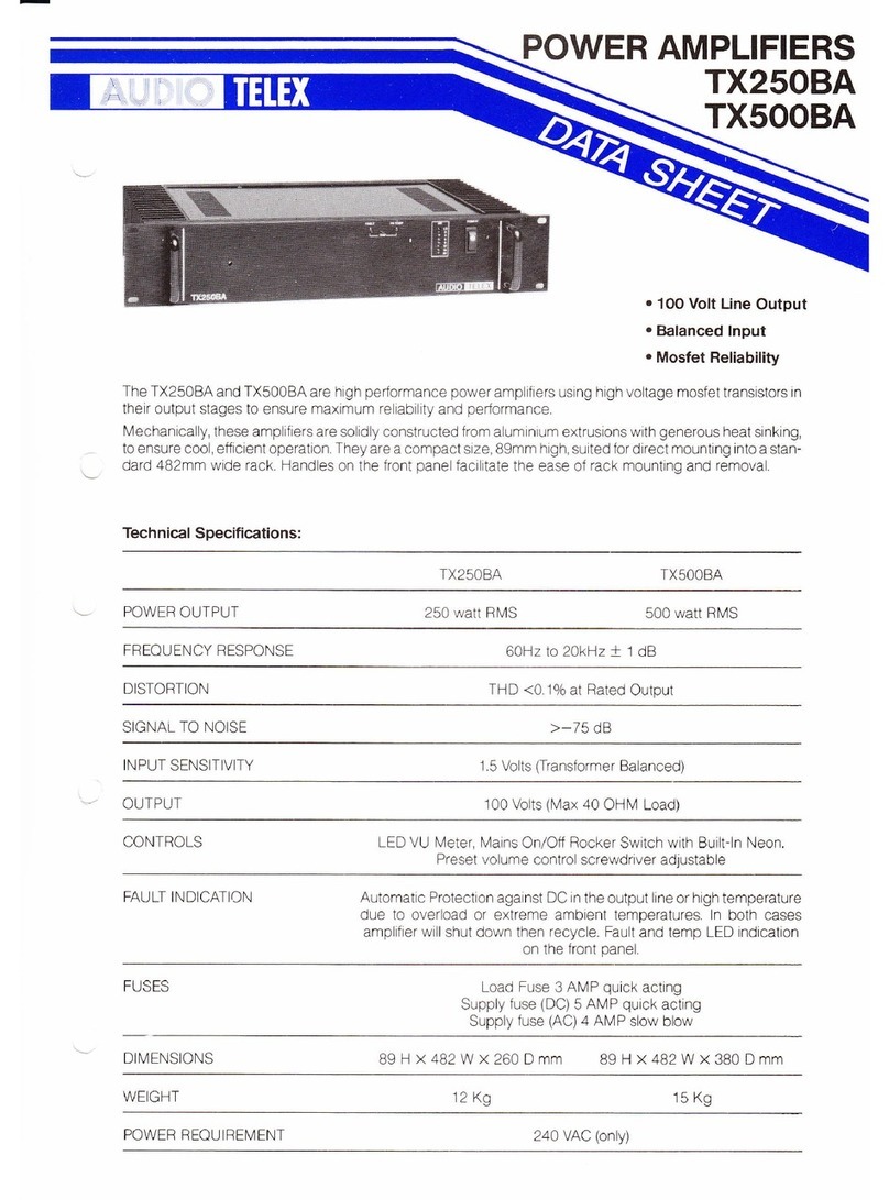
AUDIO TELEX TX250BA User manual

AUDIO TELEX

AUDIO TELEX TX250BA User manual

AUDIO TELEX ACM250P Operating and installation instructions
AUDIO TELEX

AUDIO TELEX ACM250P Operating and installation instructions

AUDIO TELEX DCM250 User manual

AUDIO TELEX

AUDIO TELEX DCM250 User manual

AUDIO TELEX SA120-1 User manual

AUDIO TELEX

AUDIO TELEX SA120-1 User manual
AUDIO TELEX AT120R User manual

AUDIO TELEX

AUDIO TELEX AT120R User manual
AUDIO TELEX DI 100 User manual

AUDIO TELEX

AUDIO TELEX DI 100 User manual
AUDIO TELEX TX30 User manual

AUDIO TELEX

AUDIO TELEX TX30 User manual
AUDIO TELEX SA250B User manual

AUDIO TELEX

AUDIO TELEX SA250B User manual
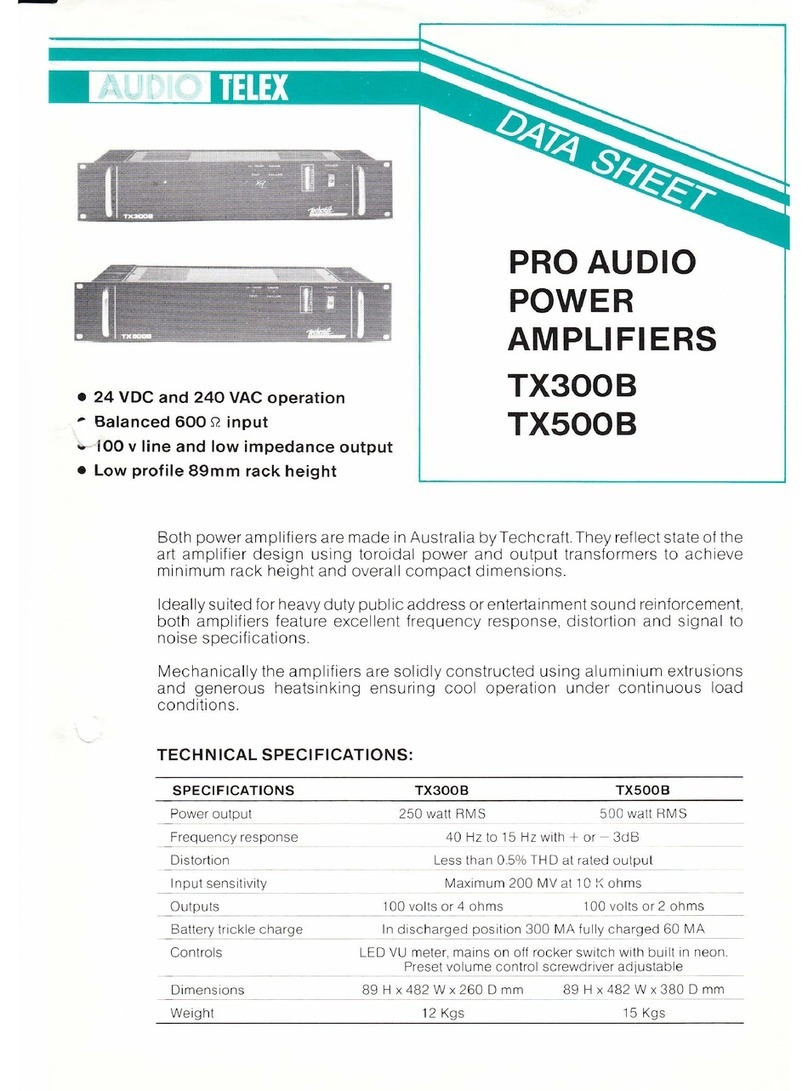
AUDIO TELEX PRO AUDIO TX300B User manual

AUDIO TELEX

AUDIO TELEX PRO AUDIO TX300B User manual

AUDIO TELEX 8182 B User manual

AUDIO TELEX

AUDIO TELEX 8182 B User manual
AUDIO TELEX ACM250 User manual

AUDIO TELEX

AUDIO TELEX ACM250 User manual
AUDIO TELEX TX3028 Operating and installation instructions

AUDIO TELEX

AUDIO TELEX TX3028 Operating and installation instructions

AUDIO TELEX IC30 Operating and installation instructions

AUDIO TELEX

AUDIO TELEX IC30 Operating and installation instructions

AUDIO TELEX ACM120R User manual

AUDIO TELEX

AUDIO TELEX ACM120R User manual

AUDIO TELEX DCM120 User manual

AUDIO TELEX

AUDIO TELEX DCM120 User manual

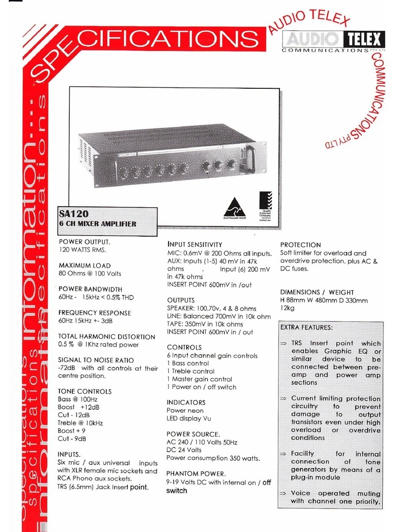
AUDIO TELEX SA120 User manual

AUDIO TELEX

AUDIO TELEX SA120 User manual

Popular Amplifier manuals by other brands
Waudio EPX Series user manual

Waudio

Waudio EPX Series user manual

Micromega M.ONE M-150 user manual

Micromega

Micromega M.ONE M-150 user manual

EMPHASER EA2500D Installation & operating manual

EMPHASER

EMPHASER EA2500D Installation & operating manual

AVPro Edge AC-DA14-AUHD user manual

AVPro Edge

AVPro Edge AC-DA14-AUHD user manual

MB QUART Q4.150 installation manual

MB QUART

MB QUART Q4.150 installation manual

Mark Bass LITTLE MARCUS owner's manual

Mark Bass

Mark Bass LITTLE MARCUS owner's manual

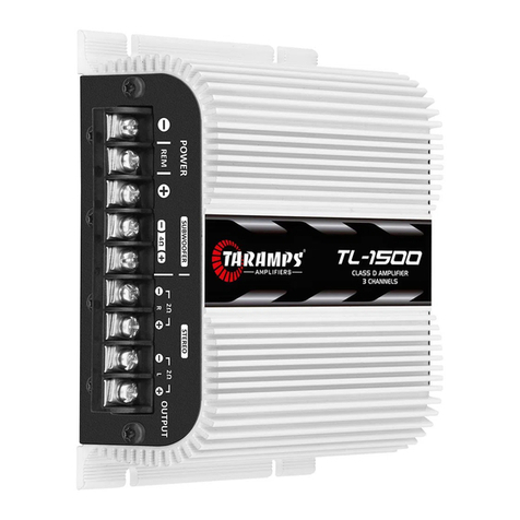
Taramp's TL-1500 instruction manual

Taramp's

Taramp's TL-1500 instruction manual

One Forall SV-9540 instruction manual

One Forall

One Forall SV-9540 instruction manual

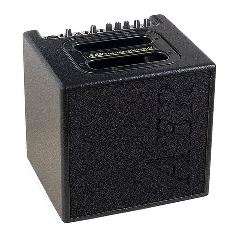
AER Alpha user manual

AER

AER Alpha user manual

Power bass XL-805DMX owner's manual

Power bass

Power bass XL-805DMX owner's manual

UNI electronic UMA 5460M user manual

UNI electronic

UNI electronic UMA 5460M user manual

Inakustik 00415004 user manual

Inakustik

Inakustik 00415004 user manual

Fezz Audio GAIA user manual

Fezz Audio

Fezz Audio GAIA user manual
Taramp's MD 800.1 instruction manual

Taramp's

Taramp's MD 800.1 instruction manual

Clear One SLX300 SpeakerLinX Installation and setup guide
Clear One

Clear One SLX300 SpeakerLinX Installation and setup guide

Power Max PM4-15 Installation & maintenance instructions

Power Max

Power Max PM4-15 Installation & maintenance instructions

MB QUART PAB 2100 Installation and operation
MB QUART

MB QUART PAB 2100 Installation and operation

EMPHASER EA-MT1 Installation & operating manual

EMPHASER

EMPHASER EA-MT1 Installation & operating manual

manuals.online logo
manuals.online logoBrands
  • About & Mission
  • Contact us
  • Privacy Policy
  • Terms and Conditions

Copyright 2025 Manuals.Online. All Rights Reserved.