Audiolab LIVE 16XL User manual

USER MANUAL / MANUAL DE USUARIO
PLEASE READ THE INSTRUCTIONS CAREFULLY BEFORE USE
POR FAVOR LEA LAS INSTRUCCIÓNES ANTES DE USAR
LIVE 16XL

p. 2LIVE 16XL
ENGLISH VERSION
p. 2LIVE 16XL
ENGLISH VERSION

Important Safety Instructions
• This are mixers for professional use. They can be used
in following electromagnetic environment: residential,
commercial and light industrial, urban outdoors.
• They are the apparatus not intended for rack mounting.
• The peak inrush currents equal to 8.33 A.
• This device complies with part 15 of the FCC Rules. Op-
eration is subject to the following two conditions: (1)this
device may not cause harmful interference,and (2)this
device must accept any interference received, includ-
ing interference that may cause undesired operation.
Changesormodicationsnotexpresslyapprovedbythe
party responsible for compliance could void the user’s
authority to operate the equipment.
NOTE: This equipment has been tested and found to com-
ply with the limits for a Class B digital device, pursuant to
Part 15 of the FCC Rules. These limits are designed to pro-
vide reasonable protection against harmful interference in a
residential installation. This equipment generates, uses and
can radiate radio frequency energy and, if not installed and
used in accordance with the instructions, may cause harmful
interference to radio communications. However, there is no
guarantee that interference will not occur in a particular in-
stallation. If this equipment does cause harmful interference
to radio or television reception, which can be determined by
turningtheequipmentoandon,theuserisencouragedto
try to correct the interference by one or more of the following
measures:
• Reorient or relocate the receiving antenna.
• Increase the separation between the equipment and re-
ceiver.
• Connecttheequipmentintoanoutletonacircuitdier-
ent from that to which the receiver is connected.
• Consult the dealer or an experienced radio/TV techni-
cian for help.
p. 3LIVE 16XL
ENGLISH VERSION

Index
p. 4LIVE 16XL
ENGLISH VERSION

Table of contents
p. 5LIVE 16XL
ENGLISH VERSION

1. Introduction
Thank you for purchasing the LIVE 16XL digital mixer.
With 20 line-level inputs, 16 microphone preampliers and
playback engine; processing with 31-band GEQ, compressor,
gate,delay,polarity;DSPeects;auxbuses;subgroups;sen-
sitive LED metering; load/save/copy mixer setting; remote
control, USB in and more, the LIVE 16XL helps you creating a
wonderful show. It is easy to operate though it has powerful
function. We suggest that you use this manual to familiarize
yourself with the features and applications for your LIVE 16XL
before using.
2. Summary of Features
• 16microphonepreamplierswithdedicatedtrimcontrol
20 line-level inputs
• 4 Aux sends and 4 subgroups, or 8 Aux sends
• 2 internal FX
• 1 stereo main out
• All channels Control Room outputs
• 2 headphones output
• USB Stereo recording
• 100mm precision motor fader
• 7 inch color LCD touch screen for graphical view and setup
• 24-bit/48KHz sampling rate
• Program, save, load & copy functions
• Digital noise gate
• Digital compressor/limiter
• Digital 4-band full parametric EQ
• PAN
• Phase reverse
• Time delay
• 6 DCA for Digital Control Audio or MUTE
• Lock and unlock function
• Change the password
• Remote Control: Ethernet or USB
• iPad App 20.4i editor for wireless control
• Expand socket for option module: Multi-track USB audio
recording module or
• CobraNet module or Dante module etc
3. Useful Data
4. Soware update
WewillalwaysupdatetheLIVE16XLsoware,please
download the latest version from below sites: WWW.AUDIO-
LAB-WEB.COM.
Since function of LIVE 16XL will also change when you
updatethesoware,thismanualcanhelpyoufamiliarwith
the basic function, for the precision, please refer to the real
LIVE 16XL digital mixer.
Note:Whenyouupdatethermware,alltheparametersyou
had saved in the mixer may be destroyed.
p. 6LIVE 16XL
ENGLISH VERSION

Control
5.1 Function buttons and knobs
1. Main input channel select buttons
There are 18 select buttons Ch1-20 as you can see on the panel.
Press this button will route its channel to add DSP setting
and assign its output. It will illuminate as has been pressed
and enabled. In DCA window, you can select group channels
by this button.
2. Main input channel knobs
The knob Ch1-16 control the gain level of the channel’s input.
Note: It is very important to properly set the level of the input
gain to minimize noise and avoid overload distortion.
The knob Ch17-20 control input level of the channels.
3. Main input signal clip indication
These LEDs beside input channel knobs indicate the input
level of Channel1-20.
4. LED meters
The LED meters show the signal status, including the output
level.
p. 7LIVE 16XL
ENGLISH VERSION

Control
• SUB1-4 or AUX5-8 & Main
Indicate the output level of SUB1-4 or AUX5-8 & Main. Please
be aware only SUB1-4 and Main button engaged can light the
corresponding meters.
• SUB1-4 or AUX5-8 button
Whenthebuttonsareo,themetersabovethemwon’tlight,
while illuminated can light the meters.
• Solo/Main meters
Indicate the output level of Solo/Main.
• Solo Meter button
Whenthebuttoniso,metersaboveitindicateoutputlevel
of main, while illuminated indicate output level of Solo.
5. Solo clear button
Press this button to clear the solo function for all of the so-
loed buses or channels.
6. Mixer/Long Faders button
Press this button twice, it will switch between Mixer and Long
Faders function.
• Mixer
Press this button, you will see mixer page on LCD screen,
where you can control all the input and output channels’
level, solo and mute, as well as DCA group level control, the
window is as below. For the detail operation, please refer to
the introduction in section 6.
p. 8LIVE 16XL
ENGLISH VERSION

Control
Long Faders
Press this button again, you will see Long Faders page on LCD
screen, where you can control all the input and output chan-
nels’ level, solo, mute, pan and rename the channel, as below
pictures show.
For the detail operation, please refer to the introduction in
section 5.
- Page of input channel 1-8
p. 9LIVE 16XL
ENGLISH VERSION

Control
- Page of output channel AUX1-4/SUB1-4
p. 10LIVE 16XL
ENGLISH VERSION

Control
7. Assign/Channel button
Press this button twice, it will switch between Assign and
Channel function.
Press this button to enter assign page, signal from a selected
input channel can
be assigned to Main, AUX1-4, Sub1-4 or AUX5-8 and FX1-2.
The window is as below. For the detail operation, please refer
to introduction in section 6.
Channel
Press this button again, you will see Channel page on LCD
screen. It gives you a preview of other function such as Polar-
ity, Delay, Link, Assign, Gate, EQ, Compressor etc.
You can also adjust corresponding parameters that show on
the screen. But for Gate here, you can only adjust threshold;
For Compressor, you can only adjust threshold; For EQ, you
can adjust nothing here.
For the detail operation, please refer to introduction in sec-
tion 6.
p. 11LIVE 16XL
ENGLISH VERSION
Control
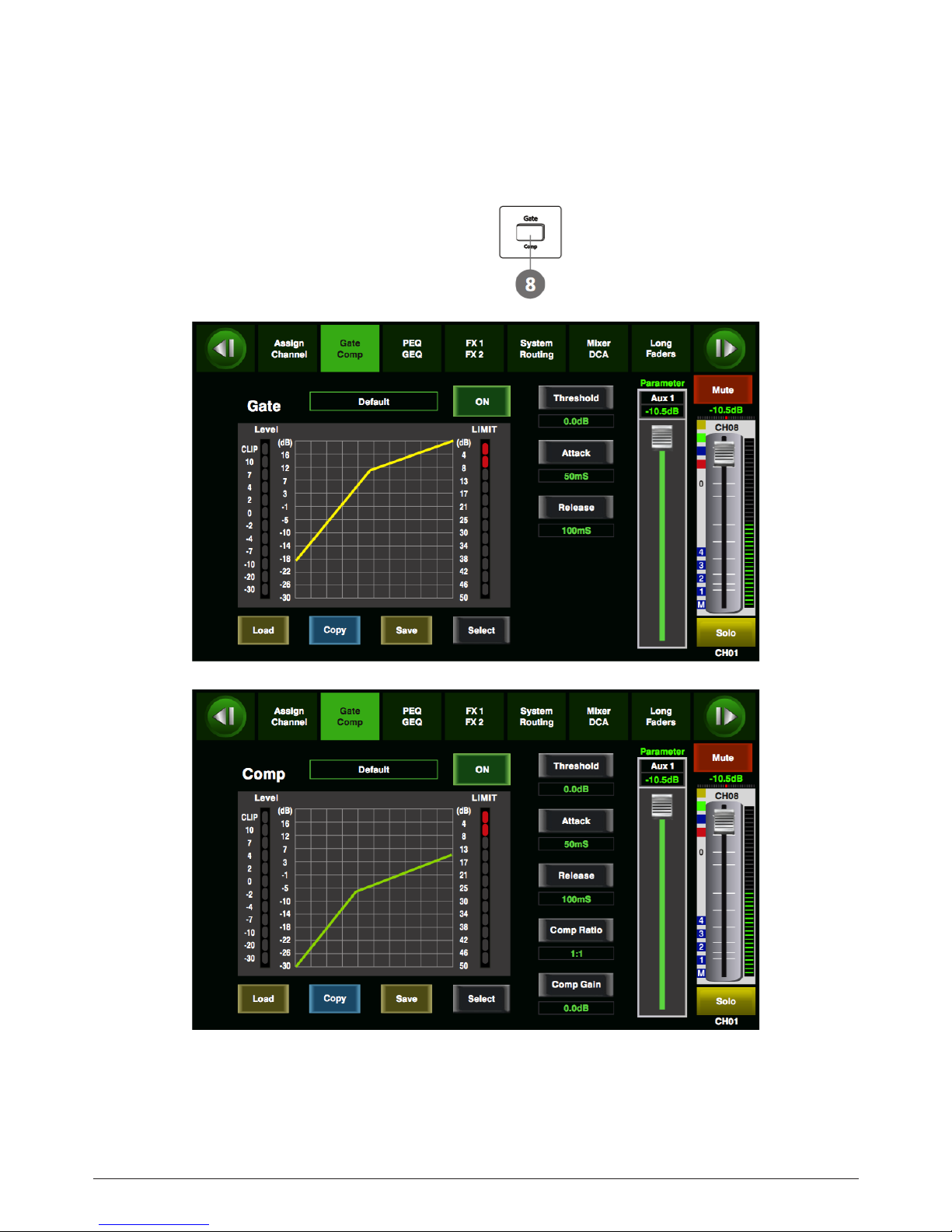
8. Gate/Comp button
Press this button twice, it will switch between Gate and COMP
function.
Gate
Noise gate attenuates signals that below the threshold and
allows signals to pass through only when they are above a
threshold setting. The window is as below. For the detail op-
eration, please refer to introduction in section 6.
Comp
A compressor reduces the level of an audio signal if its amplitude
exceeds a certain threshold. The window is as below.
For the detail operation, please refer to introduction in section 6.
p. 12LIVE 16XL
ENGLISH VERSION
Control
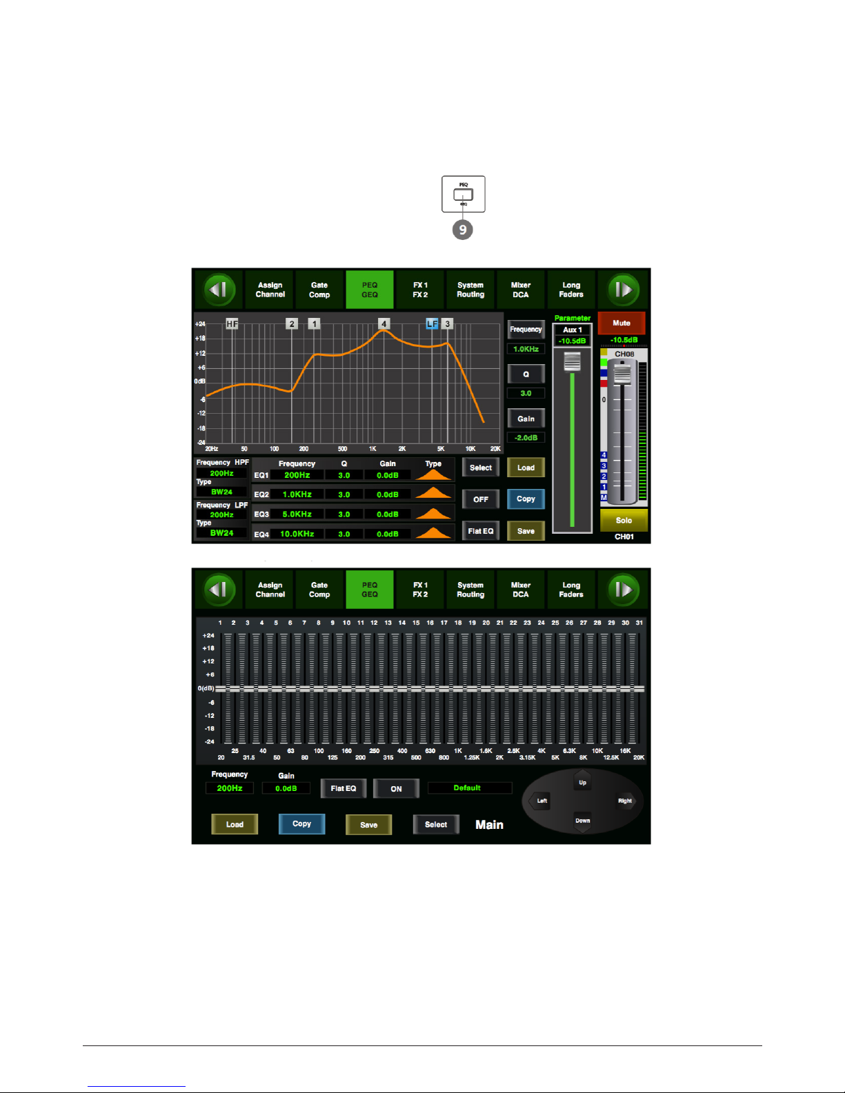
9. EQ button
Press this button twice, it will switch between PEQ and GEQ
function.
PEQ
Anequalizerisalterthatallowsyoutoadjusttheleveloffre-
quency in the range of 20Hz-20KHz. The window is as below.
For the detail operation, please refer to introduction in section 6.
GEQ
In GEQ page you can set the 31-band EQ. The window is as
below. For the detail operation, please refer to introduction
in section 6.
p. 13LIVE 16XL
ENGLISH VERSION

Control
10. FX1-2 button
Press this button twice, it will switch between FX1 and FX2
function.
Thispagecanshowandeditorthesettingofinternaleects.
EachoftheFXowns12programeects.Thewindowisasbe-
low.
For the detail operation, please refer to introduction in sec-
tion 6.
11. Digital In/Out button
Press this button twice, it will switch between Digital In and
Digital Out function. This button engages and disengages
the digital channel when you have an optional input/output
module inserted.
Digital In
The button will illuminate to indicate that current channel has
been selected as digital input. The window is as below.
For the detail operation, please refer to introduction in section 6.
p. 14LIVE 16XL
ENGLISH VERSION

Control
Digital OUT
The button will illuminate to indicate that current channel
has been selected as digital output. The window is as below.
For the detail operation, please refer to introduction in sec-
tion 6.
When the button illuminated, please pay attention to which
channel is Digital Input and which channel is Digital Output
during operation.
12. 48V Phantom button
Every microphone input equips with an individual phantom
power which is controlled by the 48V phantom power button.
When you want to turn on phantom power of some channel,
the screen will show warning to ask you and make sure. It will
illuminate when phantom power is activated.
Please notice that only the condenser microphone needs
phantom power.
Note: Please do not supply phantom power to any device
which do not need phantom power otherwise the device and
T20 may be damaged.
p. 15LIVE 16XL
ENGLISH VERSION

Control
13. Link button
Input channels, aux buses, and subgroups can be linked as
a stereo pair. It will illuminate if the stereo link button has
beenpressedandenabled.Thestereopairsarepredened
and cannot be changed. They are as follows:
Channels 1 and 2 Channels 13 and 14
Channels 3 and 4 Channels 15 and 16
Channels 5 and 6 Aux 1 and Aux 2
Channels 7 and 8 Aux 3 and Aux 4
Channels 9 and 10 Subgroups 1 and 2 or Aux 5 and 6
Channels 11 and 12 Subgroups 3 and 4 or Aux 7 and 8
A stereo link can be enabled when either channel in the
pair is selected by pressing the Link button. When the Link
button is illuminated which indicates the Stereo Link func-
tion enabled, all DSP setting, subgroup assignments, solo
status and main assignments are passed to the other chan-
nel in the pair.
Link & DCA:Aerlink,thechannelscanalsobegroupedto
DCA as stereo channel, but not able to cancel the link in DCA.
On the contrary, if the channel has been grouped to DCA, it
can not link at all, but its paired channel can link. For exam-
ple, channel 5 is linked with channel 6, then both channel
5 and 6 can be grouped to DCA. But if channel 5 has been
groupedtoDCArst,itcannotlinktochannel6,butchannel
6 can link to channel 5.
Link & Routing: The two linked channels can route as stereo
channel, while routed channels can also link later.
Please note that this is a nondestructive passing, the other
channel’sprevioussettingwillberestoredaertheLinkbut-
ton is disengaged. For example, when Channel 6 has been se-
lected, then press Stereo Link button, all of Channel 6’s setting
will be copied onto Channel 5. The Channel 5’s own setting will
restoreaertheLinkbuttonhasbeendisengaged.
14. Solo button
Press this button will send its channels or buses to the con-
trol room outputs. It will illuminate as has been pressed
and enabled.
15. Mute button
Press this button will mute selected channel and all of its as-
signed outputs. 15
It will illuminate when the button has been pressed and en-
abled.
16. Pan button
Press this button to select the Pan function, then rotate Pa-
rameter Adjust encoder to control signal level from le to
right for the selected input or output bus. If you have adjust-
ed a channel pan, please just touch 2 times on the screen and
make it back to the centre position. The LCD display shows
the setting in real time. If two channels have been linked as
stereo pair, the LCD display will automatically change to ste-
reo pan.
17. Main & SUB1-4 buttons
The selected channel can be assigned to SUB group outputs
1-4 and Main Outputs by pressing the corresponding button.
But if SUB mode is switched to AUX mode, the SUB1-4 button
can not active.
The main 20 inputs, USB In, and FX1-2 can be assigned to any or
all of the output Subgroups, Aux Sends and the main outputs.
Subgroups can only be assigned to the main outs. The 4 aux
sends cannot be assigned to a subgroup or to the main outputs.
p. 16LIVE 16XL
ENGLISH VERSION

Control
18. SUB1-4 Output Level Control knobs
These knobs here control the output level for SUB1-4 or
AUX5-8.
19. Motor Fader
There is only one motor fader to control all digital Channel’s
level, including 20 main input channels, 1 USB in, 4 AUX out-
puts, 4 Sub Group outputs, FX1-2 and 1 Main output channel
20. DCA button
Digital Control Audio(DCA) can realize group assignment.
DCA volume control will always leave the same ratio between
the channel fader levels, independent of the volume con-
trol.Pressthisbutton,itwillashuntilsomechannelshave
been selected, then press it again to save the settings and
turnothebutton.Thecorrespondingwindowisasbelow
picture show.
6.11 DCA Set interface
For the detail operation, please refer to introduction in
section 5.
p. 17LIVE 16XL
ENGLISH VERSION

Control
21. DCA1-6 buttons
Press these buttons to select which channels you want to be
assigned to the group.
22. AUX1-4 select buttons
This button function is similar to input channel select but-
tons. Press this button will route its channel to add DSP
setting and assign its output. It will illuminate as has been
pressed and enabled. In DCA window, you can select group
channels by this button.
23. FX1-2 select buttons
This button function is also similar to input channel select
buttons and AUX1-4 select buttons. For the details, please re-
fer to point 22 or 1.
24. AUX-FX Mode button
Press this button, it will illuminate as has been enabled. Sig-
nal from 20 main input channels will be assigned to AUX1-4
or AUX5-8(SUB1-4) and FX1-2, you can rotate the Parameter
Adjust knob to adjust signal’s level. When the button is OFF,
it is AUX/FX Out function, which means the AUX1-8 and FX1-2
will not enabled in Assign status.
25. Meters button
Press this button to enter meters check page, as below pic-
ture show, for the details, please refer to corresponding in-
troduction in section 6.
p. 18LIVE 16XL
ENGLISH VERSION

Control
26. FX Bypass button
ThisbuttonisforFXfunction,whenpressit,eectsofFX1-2
will be mute synchronously, which is similar to MUTE button.
27. System/Routing button
Press this button twice, it will switch between System and
Routing function.
System
Press this button to go to System page, as well as show and
edit parameters of the system, as below picture show. For the
detail operation, please refer to the introduction in section 6.
p. 19LIVE 16XL
ENGLISH VERSION

Control
Routing
Press this button again, user can select one or several chan-
nels in below windows to assign the signal to corresponding
outputs. For the detail operation, please refer to introduction
in section 6.
Page of routing input channels to AUX1 (the same with AUX2-4)
p. 20LIVE 16XL
ENGLISH VERSION
Table of contents
Languages:
Other Audiolab Music Mixer manuals


