Audiolab LIVE 24 XL User manual

P. 1
- AUDIOLAB Live 24 XL
LIVE 24 XL
24-Channel Digital Mixer
with 13 motorized faders
USER MANUAL

P. 2
AUDIOLAB Live 24 XL -
Live 24XL
24-Channel Digital Mixer with 13 motorized faders
LIVE 24XL is a powerful & intuitive 24 channel
digital mixer. The controller sports a 7" color
LCD touch screen with a unique visual interface,
in order to easily control the mix. LIVE 24XL has
parametric equalization, compressor, gate, delay,
phase inverter and DSP eects per channel. This
innovative mixer has 24 mic/line preamps with
dedicated trim control, 8 auxiliar outputs and
13 motorized 100 mm. faders, organized in two
pages. LIVE 24XL can be also controlled wirelessly
by its own app, where the user can control every
aspect of the mix with the tip of its ngers.
Specications
General
• 24 microphone/line preampliers with dedi-
cated trim control
• 13 100 mm. motorized faders
• Control room output
• Headphone output
• 7” color LCD touch screen
• 24-bit/48KHz sampling rate
• +48V phantom power
• 2 internal FX
• 8 Aux sends
• 12 DCAs
• USB Stereo recording/playback
• USB and Ethernet ports for rware update or
remote control (via iPad app)
• Digital noise gate
• Digital compressor/limiter
• Digital 4-band full parametric equalization
• Phase reverse
• Time delay
• Program, save, load & copy functions
• Automix, RTA & Talkback
• DCA for Digital Control Audio or MUTE
• Expand socket for option module: Multi-track
USB audio recording module or CobraNet
module or Dante module etc
Connectors
• 24 XLR Input connectors
• 24 TRS 1/4" Input connectors
• 8 XLR Aux send connectors
• 8 TRS 1/4" Aux send connectors
• 2 XLR Main L/R output connectors
• 2 TRS 1/4" Main L/R output connectors
• 2 TRS 1/4" Control output connectors
• 1 Input/Output USB port
• 1 Ethernet RJ-45 port
• 1 USB Remote control port
Microphone inputs
• Electronically balanced inputs
• Frequency Response to direct Output:
22Hz~20KHz at 0 dBu +/- 1.5 dBu
• Distortion (THD&N) to Main Output: <0.01%
at 0dBu 1KHz
• Signal-to-Noise Ratio: 111dB
• Maximum Input Level: +20dBu +/- 0.5 dBu
• Phantom Power: +48VDC
Line inputs
• Electronically balanced inputs
• Frequency Response to direct Output:
22Hz~22KHz at 0 dBu +/- 1.5 dB
• Distortion (THD&N) to Main Output: <0.01% at
0dBu 1KHz
• Gain: -20dBu~+30dBu
• Maximum Input Level: +20dBu +/- 0.5 dBu
1. OVERVIEW
English version

P. 3
- AUDIOLAB Live 24 XL
USB stereo inputs
• Frequency Response to Main Output:
22Hz~22KHz at 0dBu +/- 1.5dBu
• Distortion(THD&N) to Main Output: <0.01% at
0dBu 1KHz
• Maximum Input Level: 10dBu +/- 0.5dBu
Outputs
• Main max output level: +20dBu +/- 0.5dBu
• Aux send (XLR) max output level: +20dBu +/-
0.5dBu
• Aux send (1/4 TRS) max output level: +20dBu
+/- 0.5dBu
• Control room max output level: +20dBu +/-
0.5dBu
• Headphones max output level: +15dBu +/-
0.5dBu
Noise Gate
• Threshold Range: -84dBu ~ +20dB
• Attack time: 0.5mS ~ 200mS
• Relesae time: 10mS~1S
Compressor
• Threshold Range: -30dBu -+20dB
• Attack time: 10mS ~ 150mS
• Release time: 10mS ~ 1S
• Ratio: 1:1 to Limit
• Gain: 0dBu - +24dB
Digital Audio
• ADC Dynamic Range: 114dB
• DAC Dynamic Range: 114dB
• Internal Processor: 32-bit , oating point
• ADC,DAC bit depth: 24-bit
Equalization
• Low (LowPass o LowShelf): 21Hz~19.2KHz +/-
24dB
• Low-Mid: 21Hz~19.2KHz +/- 24dB
• Mid-High: 21Hz~19.2KHz +/- 24dB
• High (HighPass o HighShelf):
21Hz~19.2KHz +/- 24dB
System Crosstalk
• Input to Output (at + 0dBu 1KHz): -88dBu
• Adjacent Channels (at + 0dBu 1KHz): -87dBu
Impedances
• Mic input: 6.8 kOhm
• Line input: 75 kOhm
• Stereo input: 27 kOhm
• Other outputs: 240 kOhm
Physical
• Dimensions: 540x540x210
mm./21.2x21.2x8.3 in.
• Weight: 12 Kg/26.4 Lb.
English version
P. 4
AUDIOLAB Live 24 XL - English version
2. SAFETY RELATED SYMBOLS
To reduce the risk of electric shock please do
not remove the cover or the back panel of this
equipment.
There are no parts needed by user inside the
equipment. For service, please contact quali-
ed service centers.
This symbol, wherever used, alerts you
to the presence of un-insulated and
dangerous voltages within the product
enclosure. These are voltages that may be suf-
ecient to constitute the risk of electric shock or
death.
This symbol, wherever used, alerts you
to important operating and mainte-
nance instructions.
Protective Ground Terminal.
AC mains (Alternating Current)
Hazardous Live Terminal
ON: Denotes the product is turned on.
OFF: Denotes the product is turned o.
Caution
Describes precautions that should be observed to
prevent damage to the product.
1. Read this Manual carefully before operation.
2. Keep this Manual.
3. Be aware of all wamings reported with this
symbol.
4. Keep this Equipment away from water and
moisture.
5. Clean it only whith dry doth. Do not use sol-
vent or other chemicals.
6. Do not damp or cover any cooling opening.
Install the equipment only in accordance
with the Manufacturer's instructions.
7. Power Cords are designed for your safety.
Do not remove Ground connections! If the
plug does not t your AC outlet, seek advice
from a qualied electrician. Protect the pow-
er cord and plug from any physical stress
to avoid risk of electric shock. Do not place
heavy objects on the power. This could cause
electric shock or re.
8. Unplug this equipment when unused for
long periods of time or during a storm.
9. Refer all service to qualied service person-
nel only. Do not perform any servicing other
than those instructions contained whithin
the User's Manual.
10. To prevent re and damage to the product,
use only the recommended fuse type as
indicated in this manual. Do not short-circuit
the fuse holder.
Warning
To reduce the risk of electric shock and re,
do not expose this equipment to moisture or
rain.
Dispose of this product should not be placed
in municipal waste and should be separate
collection.
Before replacing the fuse, make sure that the
RISK OF ELECTRIC SHOCK
DO NOT OPEN.
CAUTION!
P. 5
- AUDIOLAB Live 24 XL
English version
product is OFF and disconnected from the AC
outlet.
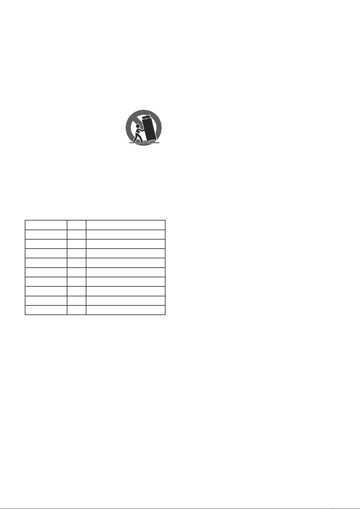
11. Move this Equipment only with a cart,
stand, tripod, or bracket,
specied by the manufac-
turer, or sold with the Equip-
ment. When a cart is used, use
caution when mobing the cart/
equipment combination to
avoid possible injury from tip-over.
12. Permanent hearing loss may be caused by
exposure to extremely high noise levels. The
US Government's Occupational Safety and
Health Administration (OSHA) has specied
the permissible exposure to noise level.
These are shown in the following chart:
According to OSHA, an exposure to high SPL in
excess of these limits may result in the loss of heat.
To avoid the potential damage of heat, it is recom-
mended that Personnel exposed to equipment
capable of generating high SPL use hearing protec-
tion while such equipment is under operation.
The apparatus shall be connected to a mains sock-
et outlet with a protective earthing connection.
The mains plug or an appliance coupler is used as
the disconnect device, the disconnect device shall
remain readily operable.
Hours x day SPL Example
890 Small gig
692 Train
495 Subway train
397 High level desktop monitors
2100 Classic music concert
1.5 102
1105
0.5 110
0.25 or less 115 Rock Concert
P. 6
AUDIOLAB Live 24 XL - English version
3. INDEX
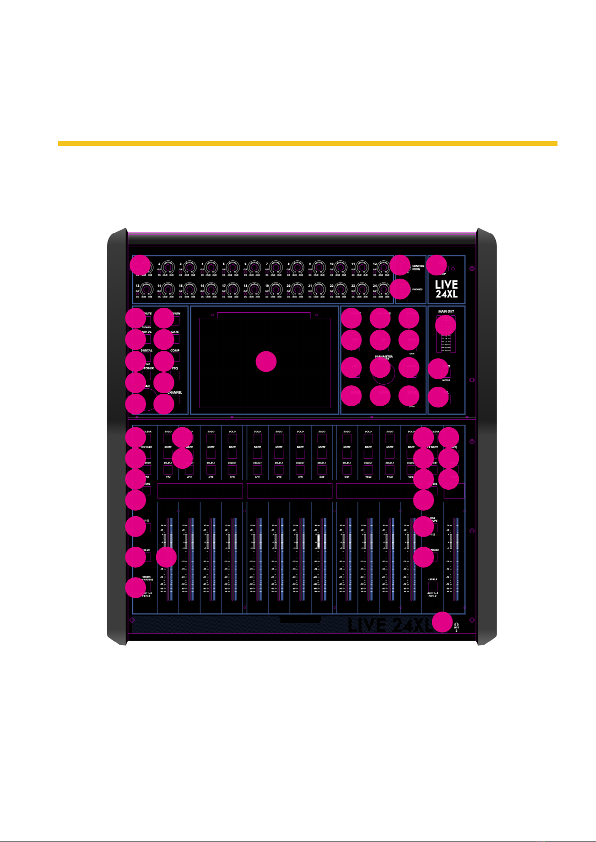
Front panel
1
4
5
6
7
8
9
10
11
12
14
15
21
19
16
21
22
21
17 41
18
21 42
20 43
31
32
33
34
36
35
44
37
38
39
13
27
28
29
30
25
25
16
26
23
24
240
3
45
P. 7
- AUDIOLAB Live 24 XL
English version
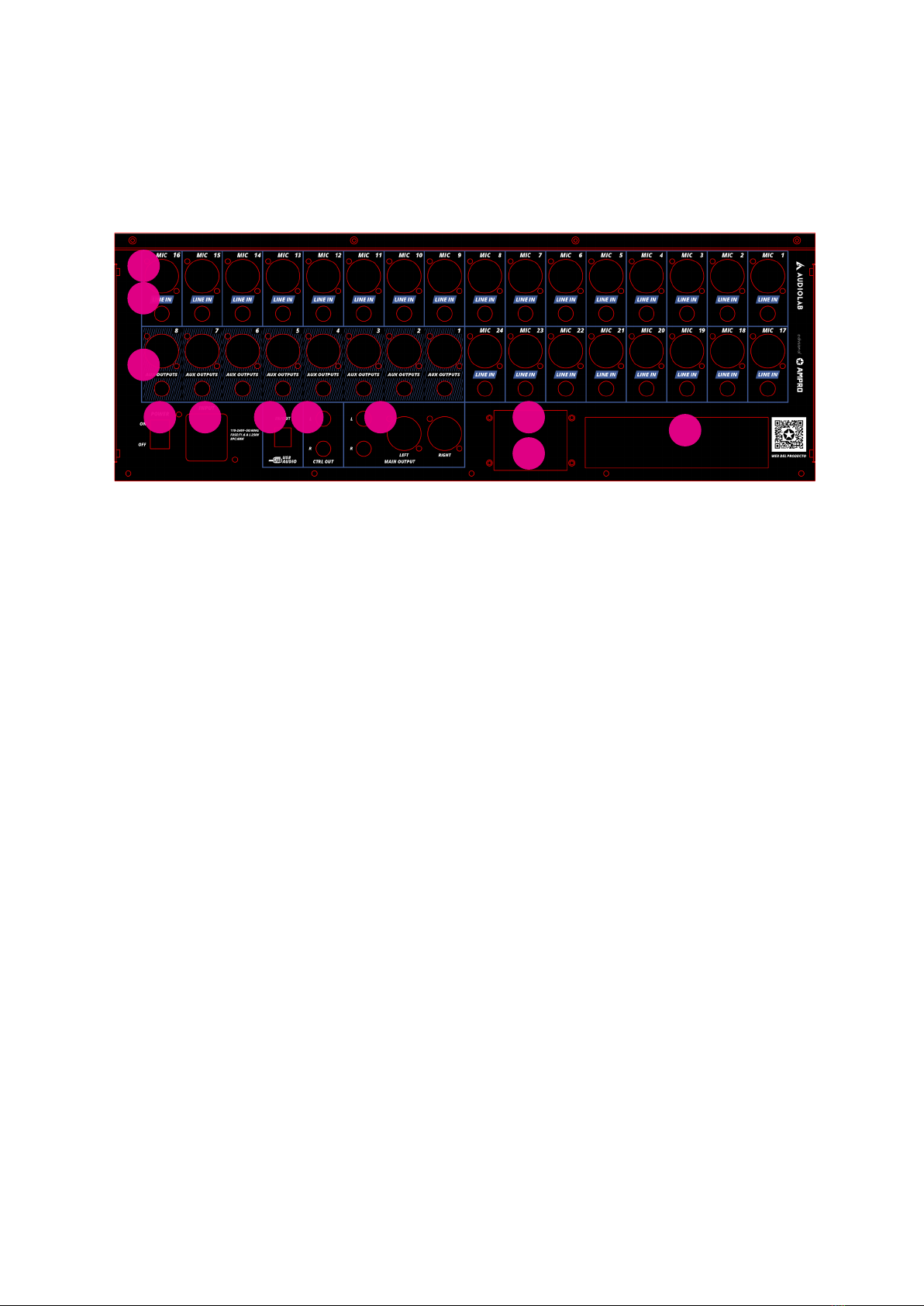
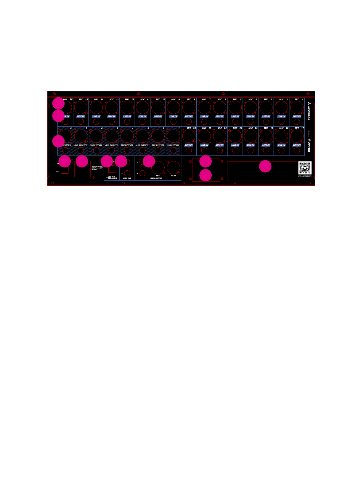
Rear panel
Under the EM disturbance, the ratio of sig-
nal-noise may be changed above 3dB.
• The mixer for professional use. They can be
used in following electromagnetic environ-
ment: residential, commercial and light indus-
trial, urban outdoors. They are the apparatus
not intended for rack mounting.
• The peak inrush currents equal to 8.33 A.
• This device complies with part 15 of the FCC
Rules. Operation is subject to the following
two conditions: (1)this device may not cause
harmful interference, and (2)this device must
accept any interference received, including
interference that may cause undesired oper-
ation. Changes or modications not expressly
approved by the party responsible for compli-
ance could void the user's authority to oper-
ate the equipment.
• Note: This equipment has been tested and
found to comply with the limits for a Class B
digital device, pursuant to Part 15 of the FCC
Rules. These limits are designed to provide
reasonable protection against harmful in-
terference in a residential installation. This
equipment generates, uses and can radiate
radio frequency energy and, if not installed
and used in accordance with the instructions,
may cause harmful interference to radio com-
munications. However, there is no guarantee
that interference will not occur in a particu-
lar installation. If this equipment does cause
harmful interference to radio or television
reception, which can be determined by
turning the equipment o and on, the user is
encouraged to try to correct the interference
by one or more of the following measures:
• Reorient or relocate the receiving antenna.
• Increase the separation between the
equipment and receiver.
• Connect the equipment into an outlet on
a circuit dierent from that to which the
receiver is connected.
• Consult the dealer or an experienced
radio/TV technician for help.
1
2
3
11 10 9 8 7 5
64

P. 8
AUDIOLAB Live 24 XL - English version
4. CONTROL
Function Buttons and Knobs
1. Ch1-24 input gain control knob The knob
Ch1-24 control the gain level of the channel's
input. Note: It is very important to properly
set the level of the input gain to minimize
noise and avoid overload distortion. When the
signal> + 18dB, this Clip LED lights green, in-
dicating the relevant channel signal overload.
When the signal> -30dB, this Sig LED lights
green, indicating the status of the relevant
channel input signal.
2. Control Room Knob This knob controls the
overall output level for control room.
3. Phones Knob This knob controls the overall
output level for headphones.
4. Route to Main Press the input channel but-
ton, then press this button, can quickly route
the input channel to main (including CH1-24,
AUX1-8 and FX1-2).
5. DC48V Phantom Power button Every micro-
phone input equips with an individual phantom
power which is controlled by the 48V phantom
power button. It will illuminate when phantom
power is activated. Note: Please notice that only
the condenser microphone needs phantom
power. Please do not supply phantom power to
any device which don’t need phantom power
otherwise the device may be damaged.
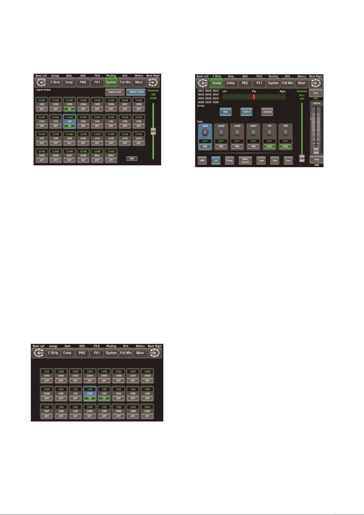
6. Digital In/Out Press this button, it will switch
between Digital In and Digital Out function.
This button engages and disengages the digi-
tal channel when you have an optional input/
output module inserted.
• Digital In: The button will illuminate to
indicate that current channel has been
selected as digital input. The window is as
below. For the detail operation, please re-
fer to introduction of DSP Control section.
• Digital Out: The button will illuminate to
indicate that current channel has been
selected as digital output. The window is
as below. For the detail operation, please
refer to introduction of DSP Control
section. When the button illuminated,
please pay attention to which channel is
Digital Input and which channel is Digital
Output during operation.
1 2
3
DC48V
Digital In
P. 9
- AUDIOLAB Live 24 XL
English version
7. Automix Press this button to activate the
Automix function. The Automix automatically
reduces the level of a microphone when it is
not being used. Consequently it lowers the
rumble, reverberation and other extraneous
noise that occur when several microphones
operate simultaneously.
8. Pan Knob The encoder controls signal level
from left to right for the selected input chan-
nel. The LCD display shows the setting in real
time. If two channels have been linked as
stereo pair, the LCD display will automatically
change to stereo pan.
9. Assign Press this button to enter assign page,
signal from a selected input channel can be
assigned to Main, AUX1-8, and FX1-2. The
window is as below. For the detail operation,
please refer to introduction of DSP Control
section.
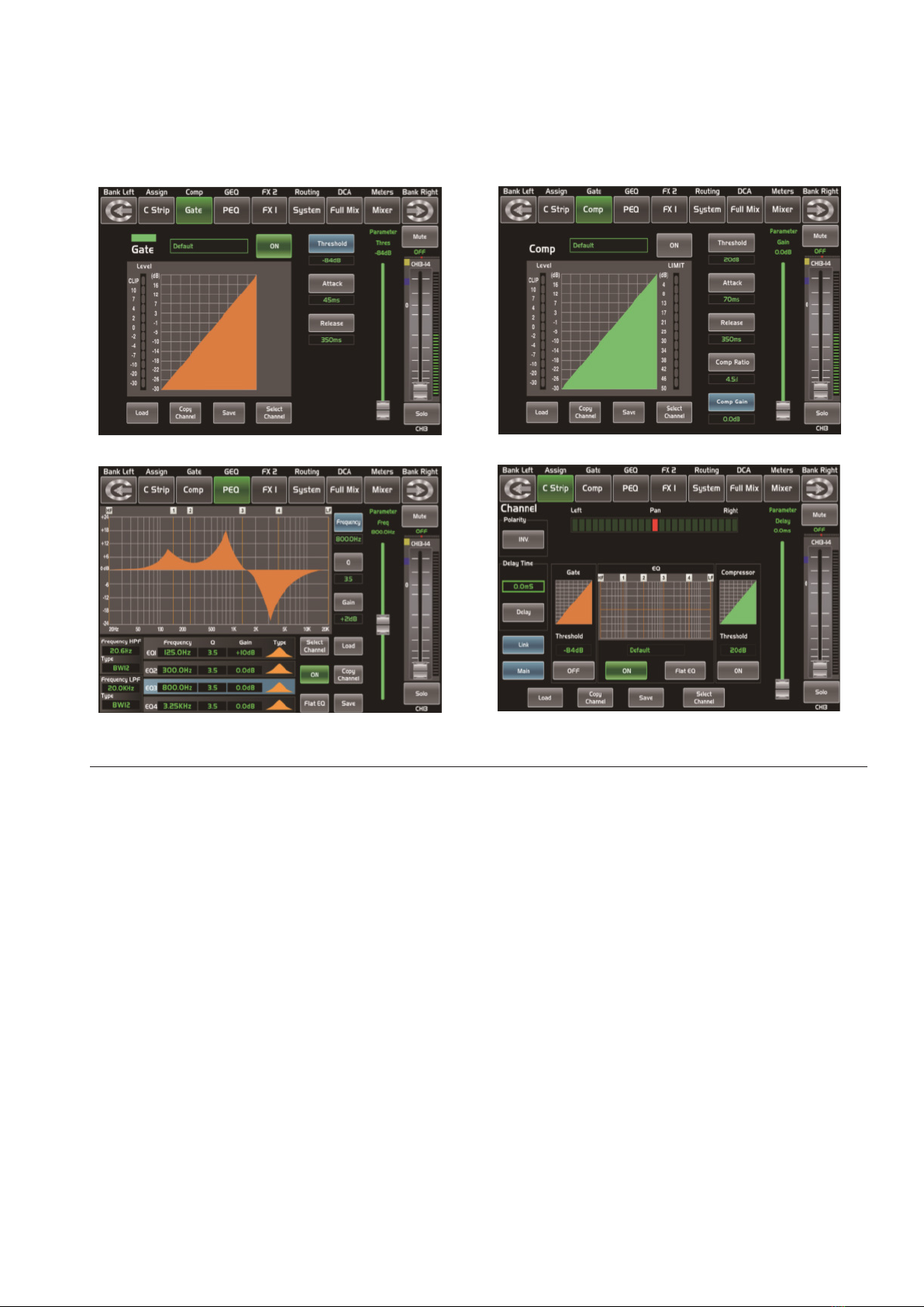
10. Gate Noise gate attenuates signals that be-
low the threshold and allows signals to pass
through only when they are above a thresh-
old setting. The window is as below. For the
detail operation, please refer to introduction
of DSP Control section.
11. Comp A compressor reduces the level of an
audio signal if its amplitude exceeds a cer-
tain threshold. The window is as below. For
the detail operation, please refer to intro-
duction of DSP Control section.
12. PEQ An equalizer is a lter that allows you to
adjust the level of frequency in the range of
20Hz-20KHz. The window is as below. For the
detail operation, please refer to introduction
of DSP Control section.
13. Channel Press this button, you will see
Channel page on LCD screen. It gives you a
preview of other function such as Polarity,
Delay, Link, Gate, EQ, Compressor etc. You
can also adjust corresponding parameters
that show on the screen. But for Gate here,
you can only adjust threshold; For Compres-
sor, you can only adjust threshold; For EQ,
you can adjust nothing here. For the detail
operation, please refer to introduction of
DSP Control section.
Automix
Digital Out Assign
P. 1 0
AUDIOLAB Live 24 XL - English version
14. FX Edit Press this button can show and editor
the setting of internal eects. Each of the FX
owns 12 program eects. The window is as
below. For the detail operation, please refer
to introduction of DSP Control section.
15. Copy Press this button and select a chan-
nel to copy the setting parameters of this
channel to other channels. For the detail
operation, please refer to introduction of DSP
Control section.
16. Routing & Sends on Faders AUX1-8/FX1-2
Press this button, users can select one or
several channels to assign the signal to corre-
sponding outputs. Routing: Press this button
to enter the assign page, select the channel
to be assigned (AUX1-8, FX1-2 and Main) and
click Enter to conrm. Sends on Faders AUX1-
8/FX1-2: The function is the same as the
Routing button. Press this button and it will
ash, then select the channel to be assigned.
For the detail operation, please refer to intro-
duction of DSP Control section.
17. System Press this button to go to System
page, as well as show and edit parameters of
the system, as below picture show. For the
detail operation, please refer to introduction
of DSP Control section.
Gate Comp
PEQ Channel

P. 11
- AUDIOLAB Live 24 XL
English version
18. Save/Load Save Used to save the current
settings (Scene, DSP, GEQ, FX). Load: used to
load presets (Scene, DSP, GEQ, FX). By press-
ing this button to achieve the switching of
save and load.
FX Edit Copy
System
Routing & Sends on Faders AUX1-8/FX1-2
Save Load

P. 12
AUDIOLAB Live 24 XL - English version
19. Mixer Press this button, you will see mixer
page on LCD screen, where you can control
all the input and output channels’ level, solo
and mute, as well as DCA group level control,
the window is as below. For the detail opera-
tion, please refer to the introduction of DSP
Control section.
20. Enter(TAP) This button can activate two
types of function.
• Enter: Conrm the edited parameter val-
ues. When there is a conrmation mes-
sage jump out on the screen, press Enter
button to answer “yes”.
• TAP: In the FX1 and FX2 page, it will
switch to TAP function, you can use this
button to enter a delay time in tempo
with the music being played. As the func-
tion of this button will be a little bit dier-
ent in dierent function, please notice the
notes that are shown on the screen when
operating.
21. UP & Down & Left & Right button These
buttons move the cursor around the display
page, or select and delete parameters and
options. Sometimes, Up button function is
the same as Left button, while Down button
function is the same as Right button. But in
GEQ, Up and Down adjust gain level, while
Left and Right adjust frequency. As the func-
tion of this button will be a little bit dierent
in dierent function, please notice the notes
that are shown on the screen when operating.
22. Adjust Parameter Knob This Encoder
adjusts the parameter values of selected
control that are shown on the LCD display.
Turning it clockwise increases the value and
counterclockwise decreases the value. As
the function of this button will be a little bit
dierent in dierent function, please notice
the notes that are shown on the screen when
operating.
23. Solo Press this button will send its channels
or buses to the control room outputs. It will
illuminate as has been pressed and enabled.
24. Mute Press this button will mute selected
channel and all of its assigned outputs. It will
illuminate when the button has been pressed
and enabled.
25. Select Button There are 12 select buttons as
you can see on the panel. Press this button
will route its channel to add DSP setting and
assign its output. It will illuminate as has
been pressed and enabled. Press ”1-12” but-
ton, which means CH1-12 correspondingly,
press “13-24” button, which means CH13-24
correspondingly, and press ”Levels” button,
which means AUX1-8 and FX1-2 correspond-
ingly. In DCA window, you can select group
channels by this button.
26. Volume Fader There are 13 faders on the
panel which is used for level adjustment of
the corresponding channel, including 12 fad-
ers for CH1-24 and 1 for Main.
27. S Clear Press this button to clear the solo func-
tion for all of the soloed buses or channels.
28. M Clear Press this button to clear the mute
function for all of the muted buses or channels.
29. Stereo Link Press this button to select the
Pan function, then rotate Parameter Adjust
encode to control signal level from left to
right for the selected input or output bus. If
you have adjusted a channel pan, please just
touch 2 times on the screen and make it back
to the centre position. The LCD display shows
the setting in real time. If two channels have
been linked as stereo pair, the LCD display
Mixer

P. 13
- AUDIOLAB Live 24 XL
English version
will automatically change to stereo pan. 22.
Link button Input channels, aux buses, can
be linked as a stereo pair. It will illuminate if
the stereo link button has been pressed and
enabled. The stereo pairs are predened
and cannot be changed. They are as follows:
Channels 1 - 2 / Channels 3 - 4 / Channels 5
- 6 / Channels 7 - 8 / Channels 9 - 10 / Chan-
nels 11 - 12 / Channels 13 – 14 / Channels
15 - 16 / Channels 17 - 18 / Channels 19 - 20
Channels 21 - 22 / Channels 23 - 24 / Aux 1 - 2
/ Aux 3 - 4 / Aux5 - 6 / Aux7 - 8. A stereo link
can be enabled when either channel in the
pair is selected by pressing the Link button.
When the Link button is illuminated which
indicates the Stereo Link function enabled, all
DSP setting, solo status and main assignments
are passed to the other channel in the pair.
• Link & DCA: After link, the channels can
also be grouped to DCA as stereo chan-
nel, but not able to cancel the link in DCA.
On the contrary, if the channel has been
grouped to DCA, it can not link at all, but
its paired channel can link. For example,
channel 5 is linked with channel 6, then
both channel 5 and 6 can be grouped to
DCA. But if channel 5 has been grouped
to DCA rst, it can not link to channel 6,
but channel 6 can link to channel 5.
• Link & Routing: The two linked channels
can route as stereo channel, while routed
channels can also link later. Please note
that this is a nondestructive passing, the
other channel's previous setting will be
restored after the Link button is disen-
gaged. For example, when Channel 6 has
been selected, then press Stereo Link
button, all of Channel 6's setting will be
copied onto Channel 5. The Channel 5's
own setting will restore after the Link
button has been disengaged.
30. Name Press this button to rename the chan-
nel. Operation: Press Name button--- Select
the channel which need to be named--- Edit
the name--- Enter.
31. DCA Clear Press this button to clear the
corresponding DCA group. Operation: Press
DCA Set button--- Select the DCA group
which need to be cleared--- Press DCA Clear
button--- Yes.
32. FX Mute This button is for FX function, when
press it, eects of FX1-2 will be mute syn-
chronously, which is similar to MUTE button.
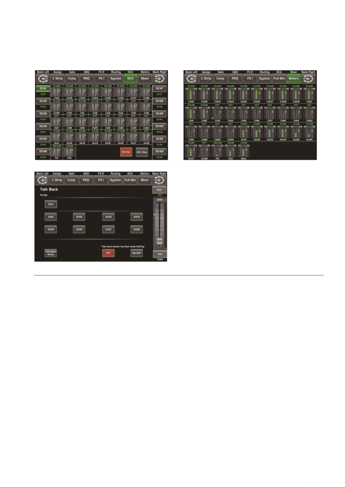
33. DCA set Digital Control Audio (DCA) can re-
alize group assignment. DCA volume control
will always leave the same ratio between
the channel fader levels, independent of
the volume control. Press this button, it will
ash until some channels have been select-
ed, then press it again to save the settings
and turn o the button. For example, if you
want to set CH1 & CH2 as DCA1, the steps
are: Press DCA Set to enable DCA setting ---
Press DCA1, then select CH1 & CH2 --- Press
DCA Set again to conrm. The corresponding
window is as below picture show. For the
detail operation, please refer to introduction
of DSP Control section.
34. Meters Press this button to enter meters
check page, as below picture show, for the
details, please refer to corresponding intro-
duction of DSP Control section.
35. Talkback Insert the microphone on the rear
panel CH24 Mic input jack. Press this button
enter the Talkback interface and the button
will be illuminated at the same time. Touch
the Talkback Active box on the screen to
enable the Talkback function. CH24 can be
assigned to Main and AUX1-8. There are two
modes: PTT mode: Select PTT mode, you
must always press the Talkback button to
speak, and release to end the speaking. ON/
OFF mode: Select ON/OFF mode, press the
Talkback button to speak.
P. 14
AUDIOLAB Live 24 XL - English version
DCA set Meters
Talkback
36. DCA Groups1-12 Press this button to activate
the DCA level adjustment function. Slide the
corresponding fader to adjust the level of
the pre-dened DCA group. If it has not been
DCA grouped, the screen will prompt "This
DCA group is not dened".
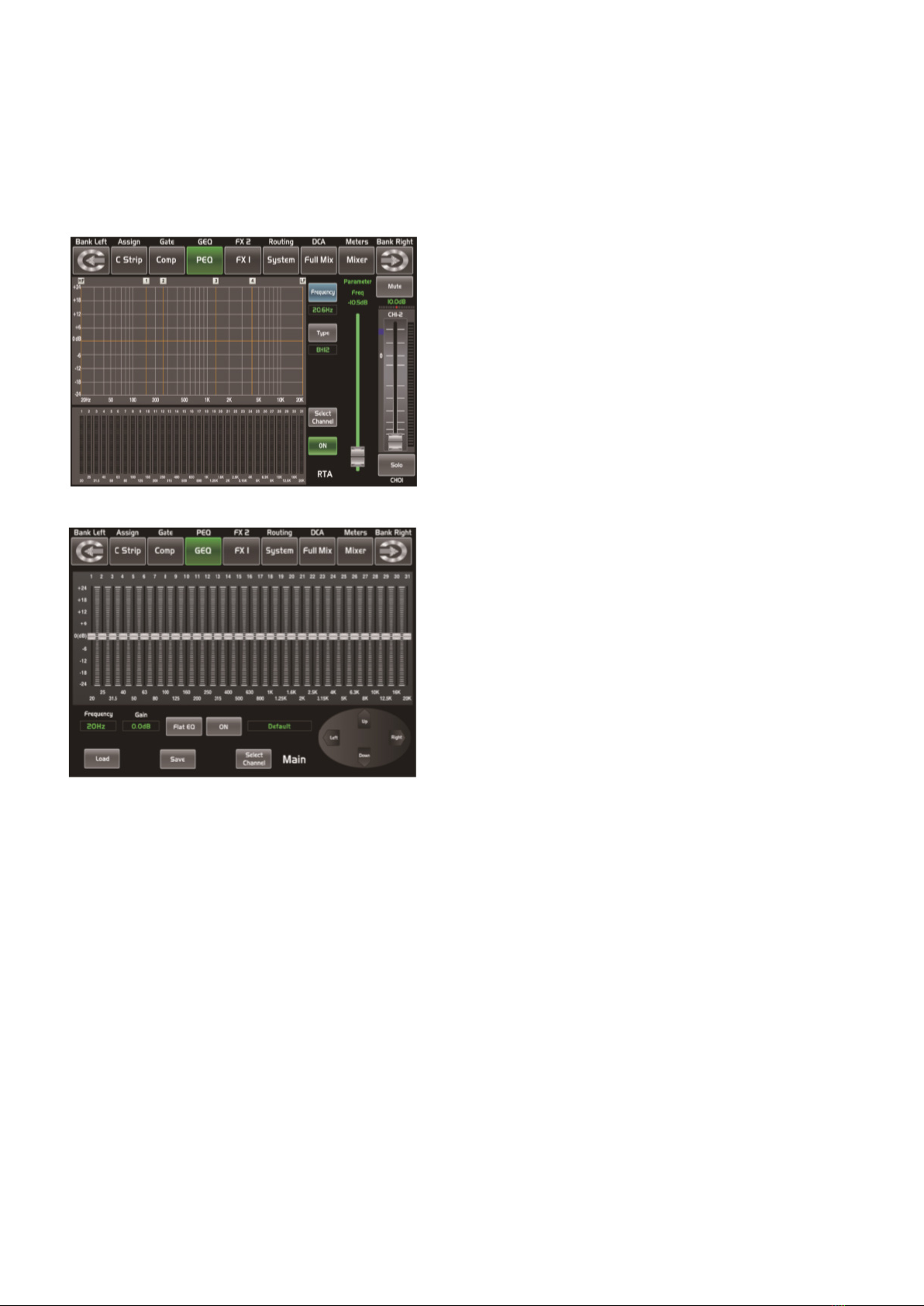
37. RTA RTA: Real-Time Analysis. Press this button
to activate the RTA function. With 31 frequency
points analysis, each frequency corresponds to
a level value, the level of each frequency can be
seen on the screen in real time.
38. GEQ Press this button to activate GEQ func-
tion (note: only for output channel). In GEQ
page you can set the 31-band EQ. The win-
dow is as below. For the detail operation,
please refer to introduction of DSP Control
section.
39. Select Main It is used for selecting Main
channel. Enter main channel interface by
pressing this button.
40. USB Lamp Connector This connector can
connect with a 5V-500mA lamp which can
help you use the digital mixer whether in
dark situation or not conveniently.
41. LED Level Indicator It indicates the level of
the MAIN channel or SOLO channel. By de-
fault, it is used to indicate the MAIN channel
level when the SOLO METER button is not
pressed.
42. Solo Meters When the button is o, meters
above it indicate input level of main, while
illuminated indicate input level of Solo.
43. PFL The default setting for the Solo bus is
After-Fader Listen (AFL); by pressing PFL,
Pre-Fader Listen is enabled. In either mode,
press Solo on any channel or bus to route
that channel to the Solo bus and has no ef-
fect on the main.
P. 15
- AUDIOLAB Live 24 XL
English version
44. HP1 This jack is used for connecting head-
phones.
45. LCD The digital mixer equips an 800*480
large LCD screen (for displaying the current
operation interface) and 13 128*64 LCD
screens (for displaying channels, channel
names, and level values).
RTA
GEQ
P. 1 6
AUDIOLAB Live 24 XL -
Rear Panel
1. MIC Input Jack This Digital Mixer equips 24
microphone preampliers for use with all
types of microphones. The preamplier has
a Class A input buer which followed by a
dual-servo gain stage. This arrangement will
bring ultra-low noise and wide gain control
which help to boost signals without increas-
ing unwanted background noise.
2. Line Input Connector This Digital Mixer is
equipped with 1/4 "balanced TRS connectors
for line input. Note: Please notice that there
will be a momentary spike in the output
when plugging in a microphone or a line-level
input device, or turning phantom power on
or o. So it should be better to mute or turn
down the channel fader before changing con-
nections or turning phantom power on or o.
3. Aux Outputs These are balanced mono
outputs for each auxiliary. The Aux mixing
will be output from these 8 Aux channels.
Aux mixing can be used for monitoring and
eects processing.
4. Optional module Select our optional module
that you want for extra function. Please con-
tact with distributor to get more information
about the optional modules.
5. USB This port is for remote control or rm-
ware update.
6. Ethernet This port is for Ethernet control or
rmware update.
7. Main Output This Digital Mixer features
both XLR and TRS main outputs.
8. Ctrl Out These are the balanced con-
trol-room outputs. The level is controlled
by the knob in the Control Room on the top
panel.
9. USB Audio In/Out This port is for USB audio
input and output. You can connect it to WIN-
DOWS/MAC system without any USB driver.
10. Power Input The provided power cable can
be plugged in.
11. Power Switch Push the top part of the switch
to turn on and the bottom part to turn o.
1
2
3
11 10 9 8 7 5
64
English version

P. 17
- AUDIOLAB Live 24 XL
5. SOFTWARE UPDATE
6. HOOKUP DIAGRAM
We will always update the Live 24XL software,
please download the latest version from below
sites: www.amproweb.com. Since function of the
Live 24XL will also change when you update the
software, this manual can help you familiar with
the basic function, for the precision, please refer
to the real digital mixer.
Note: When you update the rmware, all the
parameters you had saved in the mixer may be
destroyed.
Vocal Mics Guitar Bass
D/I Box D/I Box
Keyboards Drum
Vocal
Monitor
Keyboard
Monitor
Guitar
Monitor
Bass
Monitor
Remote Control
Through PC
English version
P. 18
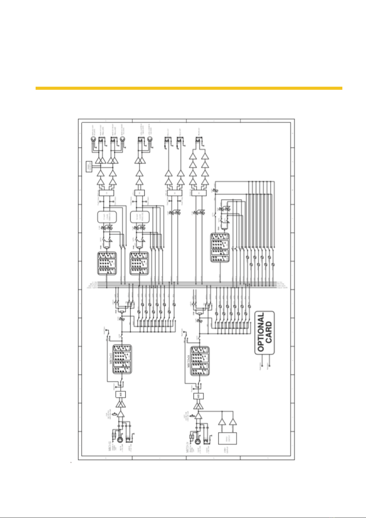
AUDIOLAB Live 24 XL -
7. BLOCK DIAGRAM
English version

P. 1 9
- AUDIOLAB Live 24 XL
8. DSP CONTROL
In addition to control directly on the machine, the
Digital Mixer can also achieve remote operation
via the app, which greatly facilitates the users.
Mixer interface
Once you turn on the mixer switch, the Mixer inter-
face will come to your eyes at rst if you have pre-
set, now let’s see what you can get in this interface.
Touch a channel, for example, CH02,
the background and corresponding CH2
button will illuminate synchronously,
you can control the output signal level
by Parameter Adjust knob. The meter on
the left indicates the level of the input
signal, and the meter on the right indicates the
level of the main channel.
Meter beside the fader indicates the input
signal level activity .This long fader can
control level of all input and output chan-
nels in this screen, but for one selected
channel at one time, all its control will
change synchronized with the selected
channel.
Meter beside the fader indicates signal
activity. The number indicates current
channel level.
The pan icon shows real pan of select-
ed channel audio signal, rotate the pan button
on the panel to adjust it.
Touch the icon to monitor selected
channel audio signal, it will illuminate
synchronized with Solo button on the panel.
Touch the icon to silence selected
channel audio signal, it will illuminate
synchronized with Mute button on the panel.
This letter shows the real current
channel. You can also rename the channel by
touching it and holding for a while, a virtual key
will come into your vision then please tap the
keyboard and give a new name to this channel
as you like.
Slide the fader, you can increase
or decrease corresponding chan-
nel’s level.
English version

P. 2 0
AUDIOLAB Live 24 XL -
Long Faders interface
Touch this icon to switch
channels and enter cor-
responding Long Faders
page, in which you can adjust channels’
basic function like pan, solo, mute, level
and rename the channel, etc.
Functions on this icon (like mute, level
number, pan, long fader, solo and chan-
nel name) are the same with that in
Mixer interface.
Assign interface
The 24 main inputs and internal FX returns can be
assigned to any or all of the outputs, Aux sends
and main outputs. Aux 1-4 and AUX5-8 can switch
to each other by touching a switch icon in this
page. First, let’s see the Aux1-4 mode as below
picture show.
Touch Main, AUX1-4 or AUX5-8 on the LCD
screen or corresponding button on the panel
to assign input channel audio to these channels
or buses. They will illuminate synchronizing
with buttons in Assign area on the panel after
pressed. To adjust output level of the channel
audio, you can rotate Parameter Adjust knob or
corresponding Main, AUX1-4 or AUX5-8 knobs on
the panel.
Touch AUX1-4 and FX1-2 on the LCD screen or
press corresponding button on the panel to
assign input channel audio to these channels
or buses. To adjust output level of the channel
audio, you can rotate Parameter Adjust knob
on the panel. Touch PRE on the screen, it will
switch to POST, the AUX & FX send will derive
its signals from all channels post-fader. If the
icon has not been pressed and not illuminate, by
default, the AUX & FX Send will derive its signal
from all channels pre-fader and all unaected by
the sending channel’s fader position. In a word,
touch PRE and switch it to POST, then you can
adjust its level by sliding fader. Otherwise, the
fader wouldn’t function on level adjustment.
Slide the fader to change selected input
channel audio. The fader function is the
same with Fader on the panel, which
can control input signal’s level, they will
change synchronously. Meter beside it
indicates the signal level activity. Pan
above fader indicates value of pan set-
ting. Solo can monitor selected channel
audio. Mute can silence selected channel
audio. Long press the name box can
rename the selected channel.
English version
Table of contents
Languages:
Other Audiolab Music Mixer manuals


