Audiotec Fischer Match PP 52DSP User manual
BY
AUDIOTEC
FISCHER
PP
52DSP
PLUG
&
PLAY
5-Kanal VersUirker
mit
integriertem
DSP
5-Channe/
Amplifier
with
integrated
DSP
I..L
CD
c
.....
en
(")
:::J"
--
CD
::J
co
en
:::J"
Dear Customer,
Congratulations
on
your purchase
of
this high-qua-
lity MATCH product.
With the
PP
52DSP, MATCH is setting new stan-
dards
in
the evolving plug & play market.
General
installation
instructions
for
MATCH
components
To
prevent damage to the unit and possible injury,
read this manual carefully and follow all installati-
on
instructions. This product has been checked for
proper function prior to shipping and
is
guaranteed
against manufacturing defects.
Before
starting
your
installation,
disconnect
the
battery's negative
terminal
to
prevent
damage
to
the
unit, fire
and/or
risk
of
injury. For
a proper performance and to ensure full warranty
coverage, we strongly recommend to get this pro-
duct installed by
an
authorized MATCH dealer.
Install your
PP
52DSP
in
a dry location with suf-
ficient air circulation for proper cooling
of
the
equipment. The amplifier should be secured to
a solid mounting surface using proper mounting
hardware. Before mounting, carefully examine the
area around and behind the proposed installati-
on location to insure that there are no electrical
cables or components, hydraulic brake lines or any
part
of
the fuel tank located behind the mounting
surface. Failure to do so may result
in
unpredictable
damage to these components and possible costly
repairs to the vehicle.
We
wish you many hours
of
enjoyment with your
new MATCH
PP
52DSP.
Yours,
AUDIOTEC FISCHER
General
instruction
for
connecting
the
PP
52DSP
amplifier
The
PP
52DSP may only
be
installed
in
vehicles
which have a negative ground electrical system.
Any other system may cause damage to the
amplifier and the electrical system
of
the vehicle.
Use
only
the
provided
MATCH cable
for
con-
nection
of
the
PP
52DSP. The use
of
other
cables can
result
in
damage
of
the
ampli-
fier,
the
head
unit
I radio
or
the connected
loudspeakers!
Prior to installation, plan the wire routing to
avoid any possible damage to the wire harness.
All cabling should
be
protected against possible
crushing or pinching hazards. Also avoid routing
cables close to potential noise sources such
as
electric motors, high power accessories and other
vehicle harnesses.
The fuse
may
only
be replaced
by
an
identically
rated
fuse
(20 A)
to
avoid damage
of
the
amplifier.
13

Connectors and control units
CD
®
®
®
0
®
14
Subwoofer Output
Connector for a passive MATCH
PP subwoofer.
AUX Input
3,5 mm jack for an external audio source like
a MP3-player navigation device, etc
..
This in-
put can either be activated automatically or
via
an
optional cable remote control.
USB Input (slave only)
Connects the
PP
52DSP to your pc.
Status LED
This LED indicates the operating mode
of
the
amplifier and which setup has been chosen.
Control pushbutton
Use this button to either switch between the
setups
or
initiate a reset
of
the device.
MicroSD card reader
MicroSD Card reader to copy vehicle specific
setups to the PP 52DSP.
®
@
@
System Connector
Connector for the MATCH cable harness.
Make sure that you only use the original ca-
ble that comes with the amplifier to connect
the PP 52DSP with your car radio.
Remote Output
The remote output has to be used to turn on/
off external amplifiers that are connected to
the RCA line outputs.
Control Input
Multifunction interface for e.g. the optional
remote control URC
2A
or other accessory.
MODE Switch
Allows modifying amplifier gain and subwoo-
fer gain as well as functionality
of
the optional
remote control URC 2A.
Line Output
Line outputs for connecting external ampli-
fiers. Make sure that the ,Remote Output" is
used to turn on these devices.

CD
Subwoofer
Output
This output provides for the connection
of
a passive
Plug & Play subwoofer like the MATCH PP 7E-D
or
PP 7S-D. The car-specific setups on our website
always mention the recommended subwoofer type.
When using a subwoofer, we strongly recommend
to connect the PP 52DSP directly to a 12 Volt sour-
ce. Refer to connection instructions
in
section 3b,
page 19.
@
AUX
Input
This input automatically detects input signals
of
ex-
ternal devices like MP3-players, navigation devices,
etc. and switches to "AUX mode". If there is no si-
gnal for more than 2 seconds on the AUX input, the
amplifier automatically switches back to the radio
signal.
If
the MODE switch no. 5 is set to "on" position, the
automatic input detection will be deactivated.
In
this
case it is possible to manually switch to AUX input
using the optionally available remote control URC
2A.
@
System
Connector
Please use this terminal only in combination with
the cable harness that
is
included in the delivery
of
the amplifier. Never ever use any other harnesses
to connect the MATCH PP 52DSP to your car radio.
Caution:
The use
of
other harnesses than the
one that is supplied with the amplifier may cause
severe harm to the amplifier, your car radio and your
loudspeakers.
In
any case the warranty will be void!
@
Remote
Output
We strongly recommend to use this output for tur-
ning on/off additional amplifiers that are connected
to the line outputs
of
the PP 52DSP. This is essential
to avoid any undesired pop noises during DSP boot
or
software update process. Additionally this output
will be turned offwhen the "Power Save Mode" (see
page 17)
of
the amplifier is active.
@ USB
Input
Connect your personal computer to the PP 52DSP
using the provided USB cable. The required PC
software to configure this amplifier can be downloa-
ded from the Audiotec Fischer website.
Please note:
It is not possible to connect any USB
storage devices etc.
@
Status LED
The status LED indicates the operation mode
of
the
amplifier. Green means that setup 1 (af1) is loaded,
orange means that setup 2 (af2) is loaded.
If it lights up red constantly, either the undervoltage
protection is active or an overheating is detected.
A flashing red light indicates that no setup is loaded.
In
that case please load a new setup via the PC tool
software or the internal microSD card reader.
(j)
Control
pushbutton
The control pushbutton allows the user to toggle
between two loaded setups ,af1" and ,af2".
To
switch between the setups, the button has to be
pressed and held for approx. 1 second. Switching
is indicated by a singular red flash
of
the Status
LED. Pressing the button for 5 seconds completely
erases the internal memory. This is indicated by a
constant flashing
of
the Status LED.
Attention:
After erasing the setups from memory
the PP 52DSP will not reproduce any audio output
until a new setup is loaded.
®
MicroSD card reader
The microSD card reader allows the user to easily
copy car-specific setups to the amplifier. First you
have to download a sound setup (e.g. from our
website www.audiotec-fischer.com) and copy it to
a microSD card. After having inserted the microSD
card into the card slot
of
the PP 52DSP, the file will
be automatically copied to the internal memory
of
the amplifier. While the copy is
in
progress, the sta-
tus LED flashes red.
It
changes to green or orange
once the process is finished. Now the microSD card
can be safely removed.
Attention: Never remove the MicroSD Card while
the copy process is
in
progress.
The PP 52DSP can manage two different setup
files. They are marked with the file extensions ,.af1"
I
,ac1" (stored
in
memory 1
of
the amplifier) or,.af2"
I
,ac2" (stored
in
memory 2
of
the amplifier). Please
note: Do not store more than one "af1" or ,ac1" and
one "af2" or ,ac2" setup file on the microSD card
at a time.
You
can download the car-specific setup files to a
microSD card on www.audiotec-fischer.com.
Please be aware that it is not possible to modify the-
se setups with the PC-tool software! 15
® Control Input
This multi-functional connector
is
designed for
MATCH accessory products like the cable remote
control URC
2A.
With this remote it is possible to
control several features
of
the amplifier. It consists
of
two rotary controls and one toggle switch.
Note that it
is
necessary to activate a connected
URC 2Aeither by setting MODE switch no.6 to "ON"
position or by the appropriate command
in
the De-
vice Configuration Menu" ofthe PC-tool software.
As long as car-specific setups are used, the func-
tions of the remote control are defined as follows
and cannot
be
changed:
CONTROL
I:
Adjusting the volume
of
the AUX input
-eliminates the need to adjust the volume
on
the
external source
CONTROL
II:
Adjusting the volume of the subwoo-
fer channels.
MODE switch: Toggling between the original sound
system
without any DSP processing and the optimized car
specific DSP sound setup for demonstration purpo-
ses.
Ifthe MODE switch
no.
5
is
set to ,ON" position, the
function
of
the switch
on
the URC 2Awill change.
In
this case it
is
possible to manually activate the
AUX input.
Ifyou create a DSP setup ofyour own then it will be
possible to change the remote's functionality with
the PC-tool software.
16
@)
MODE Switches I DIP Schalter
The six MODE switches allow adjusting the ampli-
fier gain and the functionality ofthe optional remote
control, which is especially important
in
combination
with car-specific setups where the PC-tool software
cannot
be
used.
MODE switch nos. 1 and 2 adjust the overall gain
of
all amplifier channels including line outputs.
MODE switch nos. 3 and 4 adjust the gain of the
subwoofer channels
MODE switch
no.
5 defines the function
of
the tog-
gle switch
on
the remote control
MODE switch
no.
6 activates/deactivates the remo-
te control.
® Line Output
The two Line Outputs A and B are floating-ground
low-level outputs (max 3 Vrms) for connecting ad-
ditional power amplifiers. Specially designed ,Ba-
lanced Dual Audio Transformers" avoid any ground-
loops that may cause undesired alternator noise.
Please make sure that you always turn on/off exter-
nal amplifiers using the "Remote Output"
of
the PP
52DSP. Never directly control the external amps by
a signal from the ignition switch
of
your car!

MODE Switches
Affects all seven output channels!
Onyl affects subwoofer channels!
Unique Features
of
the PP 52DSP
Power Save Mode
The Power Save Mode is incorporated
in
all car-
specific setups as well as
in
the basic setup
of
the
PC-tool software. It allows to significantly reduce
the power consumption
of
the PP 52DSP (or any
additional connected amplifier) once there's no in-
put signal for more than 60 seconds. Please note
that in many up-to-date cars with "CAN"
or
any
other internal bus structures it may happen that the
radio (and therefore the
PP
52DSP as well) remains
"invisibly" turned on for up to 45 min. after leaving
the car!
Once the "Power Save Mode is active the output
stages
of
the PP 52DSP and its "Remote Output"
will be turned off, thus reducing current draw to less
than 250 mA. The amp will turn again to full operati-
on within 2 sec. if a music signal is applied.
It is possible to either modify the turn-off time
of
60 sec. or completely deactivate the "Power Save
made" via the PC-tool
S
witch
no.
5
Mode
switch
URC
2A
OFF Mode switch on remote· control bypasses
MATCH sound optimization if pressed
ON Mode
sw
itch on
tr
emote control activates
AUX
input if pressed
MODE Switch no. 5 has no function
if
remote control is
deactivated via MODE switch no.6
Please note:
It is possible to deactivate I reactivate both Mode swit-
ches no.5 and 6 via the PC-tool software.
MCM power supply technology
This technology delivers a perfectly stabilized supp-
ly voltage for the internal amplifier stages indepen-
dent on any fluctuation
of
the battery voltage, even
during cranking the car's engine.
Like all other MATCH amplifiers the
PP
52DSP is
perfectly prepared for cars with start-/stop feature.
Please note:
Nevertheless the PP 52DSP has an undervoltage
protection. If the supply voltage drops below 9.6
volts for more than 5 seconds the amplifier goes to
"Protect mode" (Status LED lights up red).
MicroSD
The microSD card reader allows to easily configure
the DSP inside the amplifier without the need
of
directly connecting a personal computer. A large
number
of
car-specific setups is available for free
on www.audiotec-fischer.com. Simply download
your desired setup and copy it to any microSD card.
Finally insert the microSD card into the PP 52DSP
and the copy process will start automatically. After
that the amplifier is perfectly programmed to drama-
tically upgrade the sound quality
of
your car factory
audio system.
17
Installation
of
car specific sound setup files
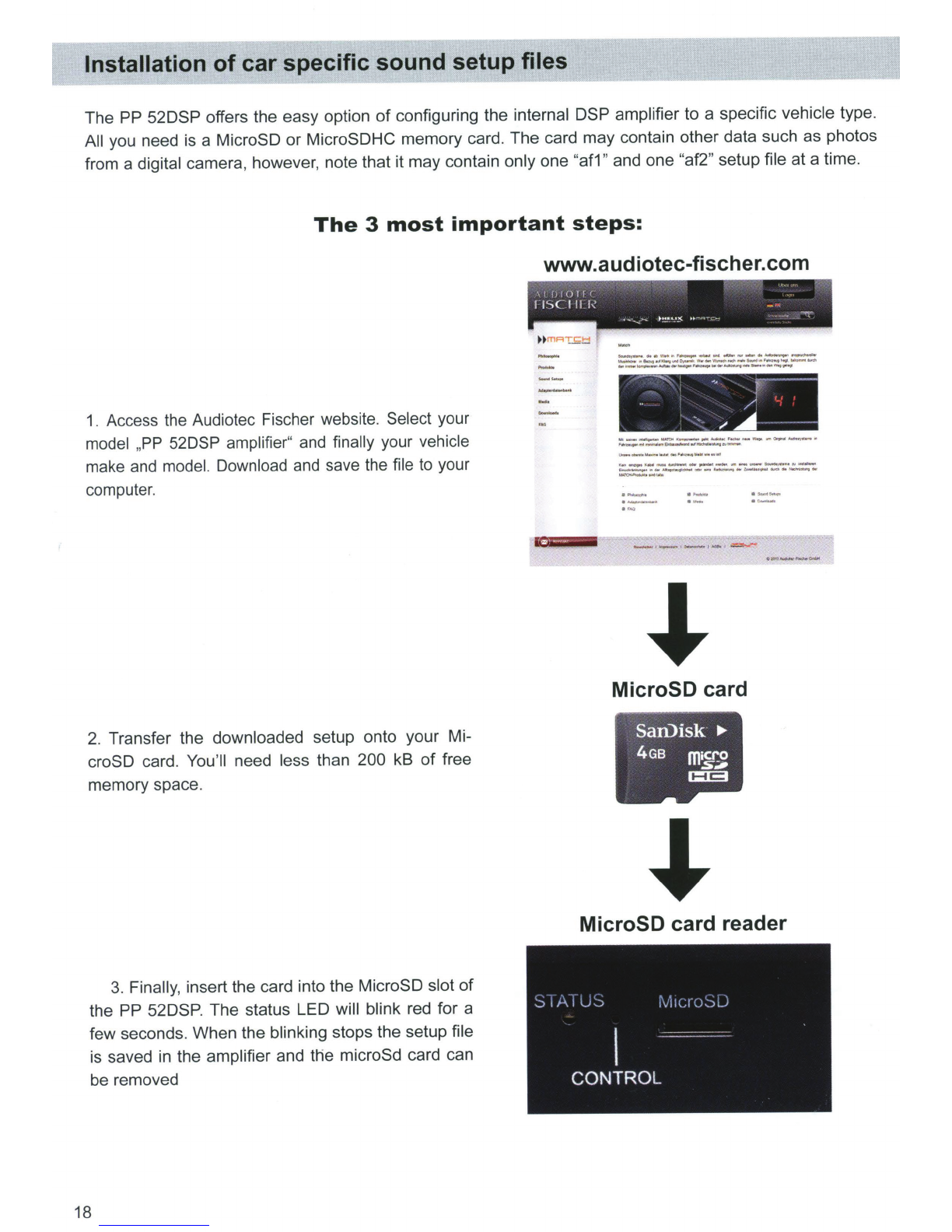
The PP 52DSP offers the easy option
of
configuring the internal DSP amplifier to a specific vehicle type.
All you need is a MicroSD or MicroSDHC memory card. The card may contain other data such as photos
from a digital camera, however, note that it may contain only one "af1" and one "af2" setup file at a time.
The
3
most
important
steps:
www.audiotec-fischer.com
1. Access the Audiotec Fischer website. Select your
model ,
PP
52DSP amplifier" and finally your vehicle
make and model. Download and save the file to your
computer.
2. Transfer the downloaded setup onto your Mi-
croSD card. You'
ll
need less than 200 kB
of
free
memory space.
3. Finally, insert the card into the MicroSD slot
of
the PP 52DSP. The status LED will blink red for a
few seconds. When the blinking stops the setup file
is saved in the amplifier and the microSd card can
be removed
18
I
I
f)
I
0
I f (
fiSC
I
II
1-i
- "
~
-
·---
•
!!."''-'~
u -
,--,_,
-~
•
-.ow-
...
_ .. ,
____
------...-
-
..
._
.........
o.o-
-----~-·-...
.....
--
...
_........_
__
......,.,
____
,.,._.
___
.......
.....,
-"'
,
--
r
..
/'
'·
·,
....
~
..
•-.......-MMOO_.,.._,
__
w.,.
...
~__,._.
,..._
..
____
........,.
..
_
MicroSD card
San.)isk
..,_
4GB
ffiiCro
,Sj#
1:13
MicroSD card reader

The MATCH
PP
52DSP
must
be connected
to
the
head
unit
(radio) as
follows:
Caution: Carrying out the following steps will
require special tools and technical knowledge.
In
order to avoid connection mistakes and/or dama-
ge, ask your dealer for assistance if you have any
questions and follow all instructions
in
this manual
(see page 13).
1.
After removing the radio from the dash using
appropriate tools, disconnect the vehicle harness
from the radio. Next, connect the vehicle harness
to the male connector
of
the MATCH cable harness,
see fig. 3
G)
Depending
on
your car
an
additional car-specific
adaptor may be required.
A list
of
all cars and the respective adaptors can be
found on www.audiotec-fischer.com.
2. Connect the female connector
of
the MATCH
cable harness or the car-specific adaptor to the ra-
dio, see fig. 3
®.
3. There are two alternatives which are described
in
sections
3a
and 3b to connect the
PP
52DSP
to power. As long as a subwoofer is connected to
the PP 52DSP, we recommend to use alternative
3b (depending
on
wire gauge and fuse rating
of
the
vehicle's harness).
Short interrupts
in
music reproduction at high liste-
ning levels are an indicator for significant voltage
drops
on
the power supply due to insufficient vehi-
cle cable harness dimension.
3a. Power supply via vehicle cable harness:
In
this case the PP 52DSP will be directly powered
from the vehicles radio harness. Carefully check
its wire gauge and fuse rating first. Iffuse rating is
significantly lowerthan 20Athen we strongly recom-
mend
option 3b.
Depending on the vehicle type, the connections for
switched (ACC+) positive terminal and constant po-
sitive terminal can be different. The PP 52DSP must
not be powered using the switched positive terminal
as this might result
in
da-mage to the vehicle's elec-
tronic circuits. Verification
of
the right terminal must
be made prior to activation
of
the unit at connec-
tions
®
(yellow) and
®
(blue) with a voltmeter.
The constant positive wire is identified by a reading
of
12V even when the vehicle is turned off. After
measuring, connect cable
@to
the constant posi-
tive terminal (compare fig.
4).
If
you
are unable
to
identify
the
appropriate
wires, please
ask
your
dealer
for
help.
3b. Direct power supply via the battery:
Ifthe power supply
of
the PP 52DSP cannot be pro-
vided via the vehicle cable harness (max. 20A), you
have to connect it directly to the car battery.
To
do
so, disconnect
joints®
(ground) and
Q)
(+12V)
of
the MATCH harness (refer
to
fig.
5).
Next, the
ground cable (min. AWG14 I 2.5 mm2) should be
connected to a common ground reference point
(this is located where the negative terminal
of
the
battery is grounded to the metal body
of
the vehi-
cle), or to a prepared metal location
on
the vehi-
cle chassis, i.e.
an
area which has been cleaned
of
all paint residues.
Always
disconnect
the
car
battery's negative terminal before
you
execute
the
following
steps. Connect the +12V power ca-
ble (min.
AWG14/2.5
mm2) to the positive terminal
of
the battery. The positive wire from the battery to
the PP 52DSP harness connection needs to have
an inline fuse (20 A) at a distance
of
no more than
12
inches
(30 em)
from
the battery. Insulate the
now unused connections
of
the MATCH harness
with tape or other appropriate material.
You
can
now reconnect the car battery. If one
of
the cable
extensions PP-EC
11,
PP-EC25 or PP-EC40 will
be used, the separate power supply has to be con-
nected to the extension cable.
4.
Connect the MATCH harness to the MATCH PP
52DSP, see fig. 3
@.
Optimizing
the
amplifier
gain setting:
Turn the car radio
on
and the volume up gradual-
ly.
Maximum volume has been reached when lou-
dspeaker distortion becomes audible.
To
increase
volume range
of
the radio use the MODE switches
nos. 1 and 2 (refer to page 17) to reduce the overall
gain
of
the
PP
52DSP. If your radio is at maximum
volume without any distortion being audible, you
can use the MODE switches to increase the am-
plifier overall gain by +2 dB. Be careful when using
this function.
19

Caution:
The PP 52DSP
amplifier
typically
has
a
higher
power
output
than
the
car
radio
itself.
Most
of
the
OE
speakers
in
the
car
will
be
able
to
handle
this
extra
power
easily.
Nevertheless
please
take
care
when
you
crank
up
the
volume.
If
you
hear
strong
distortion,
please
reduce
the
volu-
me
to
an
appropriate
level
in
order
to
avoid
da-
maging
your
speakers.
Fig. 3 Connection
of
the amplifier to the car radio
Note
-Cars
equipped
with
MOST
bus:
In
cars
equipped
with
MOST
bus
structure
it
is
mandatory
to
unplug
the
fiber-optic
cable
from
the
original
radio
connector
and
insert
it
into
the
radio
connector
of
the
MATCH
cable
harness,
which
has
a
dedicated
recess
for
this.
Female
connec-
tor
for
original
cable
harness
Male
and
female
connector
for
original
cable
harness
or
car-specific
adaptor
G)
The ISO female connector will either be plugged into the vehicle harness that has been dis-
20
connected from the car radio or a car-specific adaptor.
~
The
ISO male connector will either be plugged into the car radio
or
into a car-specific adaptor.
The 20-pole connector will be plugged into the MATCH PP 52DSP amplifier.
Optional: car-specific
adaptor-
such an adaptor may be required ifthe ISO connectors
of
the
provided PP 52DSP cable harness does not fit into your car radio.
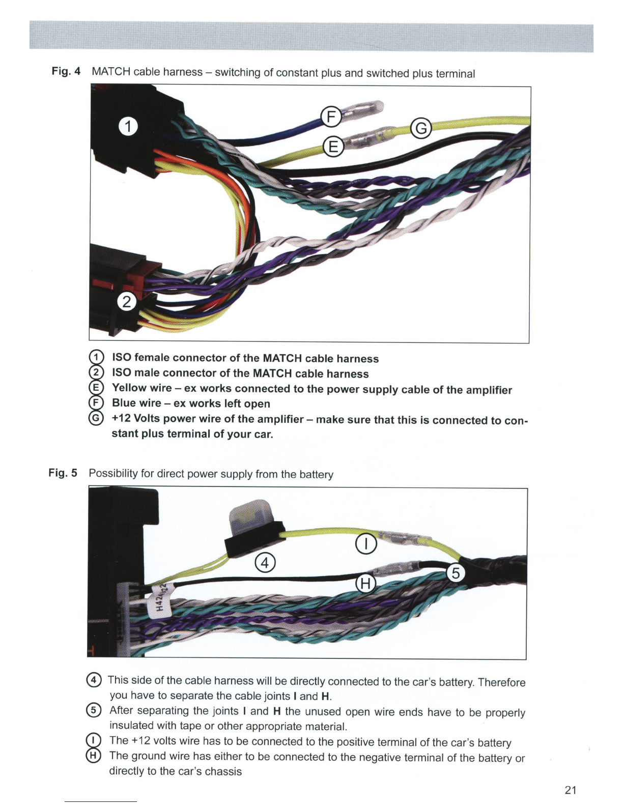
Fig. 4 MATCH cable
harness-
switching
of
constant plus and switched plus terminal
ISO female connector
of
the MATCH cable harness
ISO male connector
of
the MATCH cable harness
Yellow
wire-
ex works connected
to
the power supply cable
of
the amplifier
Blue wire -
ex
works left open
+12 Volts power wire
of
the
amplifier-
make sure that this
is
connected to con-
stant plus terminal
of
your car.
Fig. 5 Possibility for direct power supply from the battery
0 This side
of
the cable harness will be directly connected to the car's battery.Therefore
you have to separate the cable joints I and
H.
®
After separating the joints I and H the unused open wire ends have to be properly
insulated with tape
or
other appropriate material.
The +12 volts wire has to be connected to the positive terminal ofthe car's battery
The ground wi
re
has either to be connected to the negative terminal of the battery or
directly to the car's chassis
21

Connection to a PC
It is possible to freely configure the PP 52DSP with
our DSP PC-tool software.The user interface is de-
signed for easy handling
of
all functions and allows
to individually adjust all seven DSP channels.
Priorto connecting theamplifierto your PC, visit our
website and download the latest version
of
the PC-
tool software. Check from time to time for software
updates in order so that your amplifier is always up-
to-date.
You
will find the software and the respective user
manual on www.audiotec-fischer.com.
We strongly recommend to carefully read the user
manual before using the software forthe first time in
order to avoid any complications and failures.
Make sure that the amplifier is not connected to
your computer before the software and USB driver
is installed!
To
install the software follow the next steps:
1. Download the PC-tool software from the web-
site www.audiotec-fischer.com
2. Install the software on your computer. During
that process the required USB driver will be au-
tomatically installed as well.
3.
After the software installation processed is
completed you can nowconnect the amplifier to
your PC using the provided USB cable.
4.
Turn the amplifier on and then start the soft-
ware.
If
the firmware
of
the amplifier is not the
latest version itwill automatically be updated on
the currently selected memory position.
5.
You are now ready to configure the PP 52DSP
according to your demands.
ATF DSP PC-Tool
Channel
configuration
Highpass filter
Low pass filter
Equalizer
22
Device
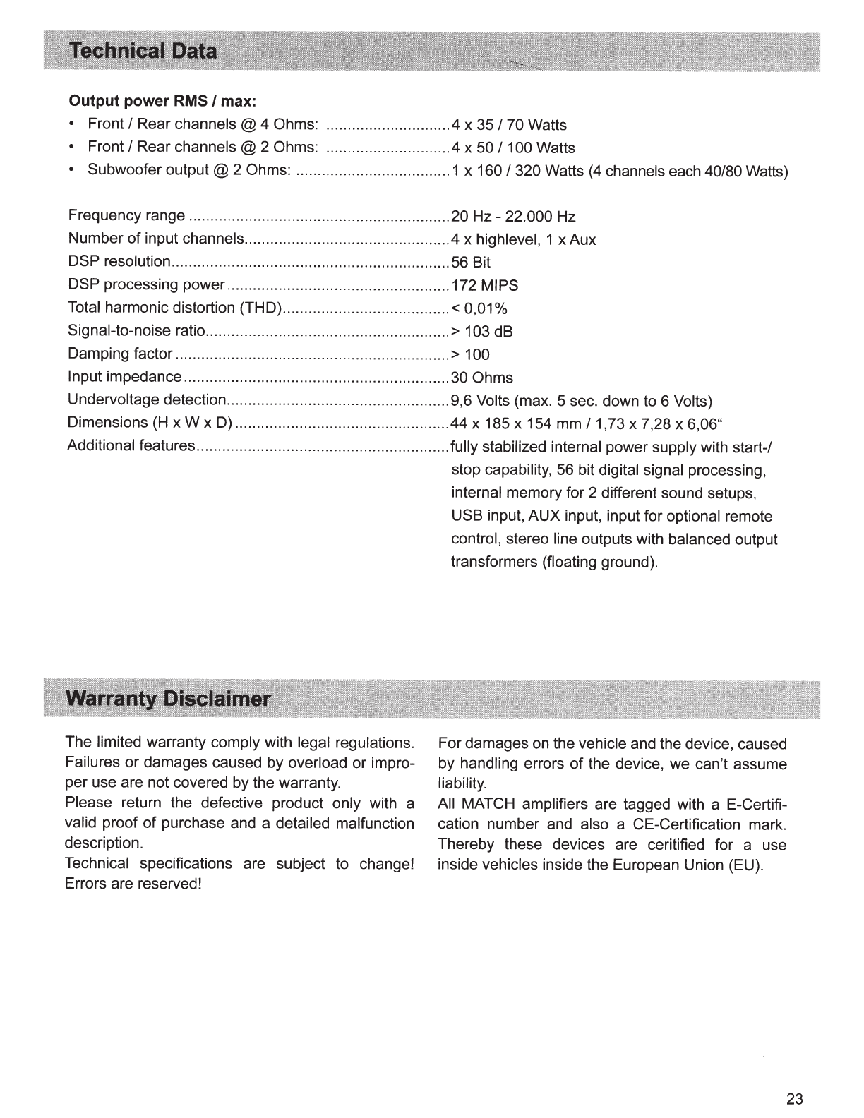
Output power RMS
I
max:
• Front I Rear channels @ 4 Ohms: .............................4 x 35 I 70 Watts
• Front I Rear channels @ 2 Ohms: .............................4 x 50 I 100 Watts
• Subwoofer
output@
2 Ohms: ....................................1 x 160 I 320 Watts
(4
channels each 40/80 Watts)
Frequency range .............................................................
20Hz-
22.000 Hz
Number of input channels................................................4 x highlevel, 1 x Aux
DSP resolution.................................................................56 Bit
DSP processing power....................................................172 MIPS
Total harmonic distortion (THO).......................................<
0,01
o/o
Signal-to-noise ratio.........................................................
>
103 dB
Damping factor ................................................................> 100
Input impedance..............................................................30 Ohms
Undervoltage detection....................................................9,6 Volts (max. 5 sec. down to 6 Volts)
Dimensions
(H
x W x
D)
..................................................44 x 185 x 154
mm
I 1,73 x 7,28 x 6,06"
Additional features...........................................................fully stabilized internal power supply with start-/
stop capability, 56 bit digital signal processing,
internal memory for 2 different sound setups,
USB input, AUX input, input for optional remote
control, stereo line outputs with balanced output
transformers (floating ground).
The limited warranty comply with legal regulations.
Failures or damages caused by overload or impro-
per use are not covered by the warranty.
Please return the defective product only with a
valid proof
of
purchase and a detailed malfunction
description.
Technical specifications are subject
to
change!
Errors are reserved!
For damages
on
the vehicle and the device, caused
by handling errors of the device, we can't assume
liability.
All MATCH amplifiers are tagged with a E-Certifi-
cation number and also a CE-Certification mark.
Thereby these devices are ceritified for a use
inside vehicles inside the European Union (EU).
23

AUDIOTEC
FISCHER
Audiotec Fischer GmbH
Gewerbegebiet Lake
II
· Hunegraben 26 · D-57392 Schmallenberg
Tel.: +49 2972 9788 0 · Fax: +49 2972 9788 88
E-mail: [email protected] · Internet: www.audiotec-fischer.com
Other manuals for Match PP 52DSP
1
Table of contents
Other Audiotec Fischer Car Stereo System manuals


Popular Car Stereo System manuals by other brands


Sony
Sony CDX-GT630UI - Cd Receiver Mp3/wma/aac Player Installation/connections

J&M Corporation
J&M Corporation JMDM-IPBT-GL18 Installation & operation instructions
 operating instructions")
Sony
Sony CDX-GT08 (CDXGT08) operating instructions

Sony
Sony DVX-11A - Car Mp3/dvd/cd Single Player operating instructions

Axis
Axis AX1505BT installation manual

Bosch
Bosch Blaupunkt Coburg MR 23 Service manual