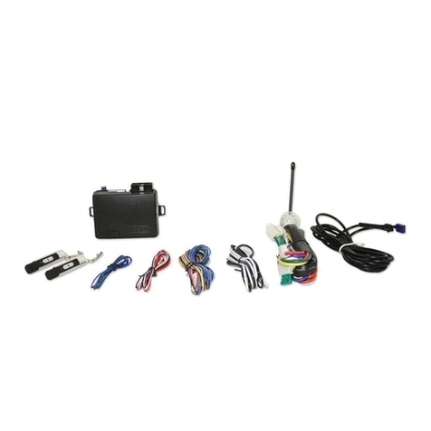
ThePRO-9675FT4RemoteStart/AlarmSystemisdesignedtobeusedwithAutomatic Transmission
Vehicles Only! The unit provides a selectable ignition control that allows a number of selectable timed
outputs for glow plug pre-heat which may be required for certain diesel vehicles, (see selectable feature #9). If
the diesel engine has a instant fire, (no glow plug pre-heat system), feature #9 should remain in the
defaultGasolinemodesetting.Fordieselapplications,consultyourdealerforthe type of ignition system
used in your particular vehicle. Regardless of the vehicle, Gasoline or Diesel, for every installation, the
vehicle MUST HAVE a Tach Signal Input, and an Automatic Transmission.
INSTALLATION OF THE MAJOR COMPONENTS:
CONTROLMODULE:
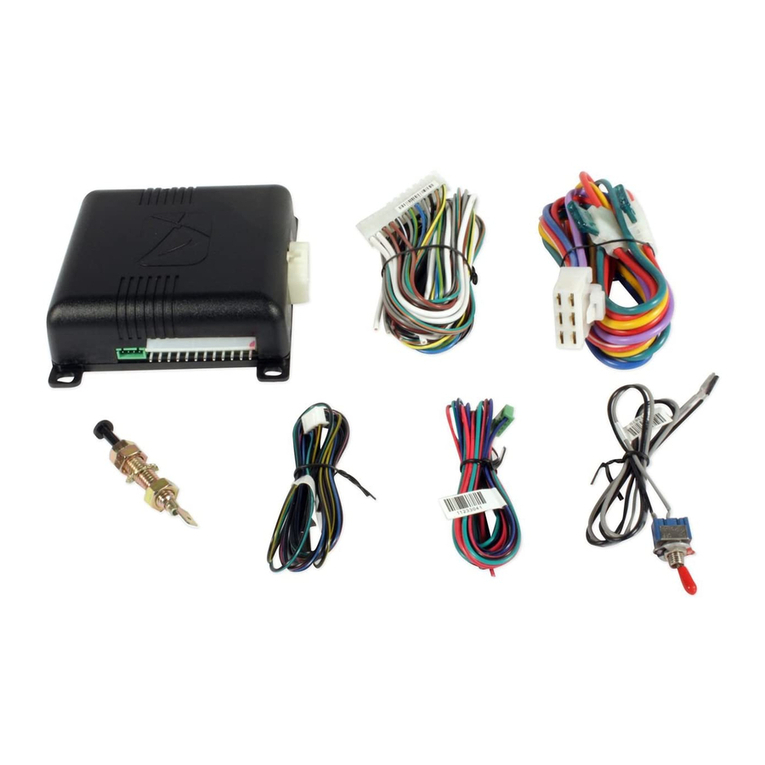
Selecta mounting locationinsidethe passenger compartment(upbehind the dashboard). Themounting
locationselectedmustbewithin24"oftheignitionswitch wiring harness to allow connection of the 6 pin
mainwiring harness.
Becertain that the chosen location will notinterferewithproper operation of the vehicle. Avoid mounting
the module to or routing the wiring around the steering shaft/column, as the module or wiring may wrap
around or block the steering wheel preventing proper control of the vehicle. Secure the module in the
chosen location using cable ties or screws as necessary.
DoNotMountTheModuleIn The Engine Compartment, as it is not waterproof.
SIREN:
Selectalocationintheenginecompartmentthatisnot accessible from below the vehicle. The selected
locationmustbe clear of hot or moving parts within the enginecompartment Thesirenmust be pointed
downwardto prevent waterretentionandthe flared endmustbepointed away fromandoutof the engine
compartment for maximum sound distribution. Before securing the siren, check behind your chosen
locationto assure that the mounting screws will notpenetrateanyfactorywiring or fluid lines. Secure the
sirenmountingbracket using #8 self taping screws or by first using themountingbracketas a template,
scribeormarkthethreebracketmountingholes. Drill the marked holes using a 1/8" drill bit, then mount
the siren using #8 sheet metal screws.
HOODAND TRUNK PIN SWITCHES:
The pin switches included in this package are intended for protecting the hood and trunk areas of the
vehicle. In all cases, the switch must be mounted to a grounded metal surface. When the pin switch is
activated,(hood/trunk open), it will supplyagroundto the input wireactivatingthealarm. In addition, the
hoodswitch is requiredforthesafety shut downoftheremote start unit. Ifthevehicleis being workedon,
this hood switch prevents the remote start activation even if the RF command to start is issued. This
switch must be installed in all applications, failure to do so may result in personal injury or property
damage.Mounttheswitchesinthehoodandtrunklocationsaway from water drain paths. If necessary,
the included brackets may be used to move the switch away from rain gutters or allow mounting to the
firewallbehind the hood seal. In both casesthe switch must be set uptoallow the hood or trunk doorto
depress the switch at least 1/4 inch when the hood or trunk is closed and fully extended when the hood
or trunk is opened. For direct mounting, a 1/4 inch hole must be drilled. Carefully check behind the
chosen location to insure the drill will not penetrate any existing factory wiring or fluid lines. Drill a 1/4"
hole in the desired location and thread the pin switch into it using a 7/16" nut driver or deep well socket.
Ifusing the mounting bracket, first secure the brackettothedesiredlocationand secure the pin switch in
thepre-threaded mounting bracket hole.
DASHMOUNTEDLED:
ThesmallRedLEDincludedinthekit willserveasavisualindicatorofthealarm's statusandprovidea
visual deterrent to a potential thief. The LED also provides important feed back information during the
transmitterand featureprogrammodes. The LED shouldbeinstalled inthedash in anareahighly visible
so that it may be seen from the driver's seat as well as from outside the vehicle. Inspect behind the
chosenlocation to insure thatthedrillwill not penetrate anyexistingfactorywiring or fluid lines. Carefully
2
