Auer Signal Ex ResistTel MB User manual
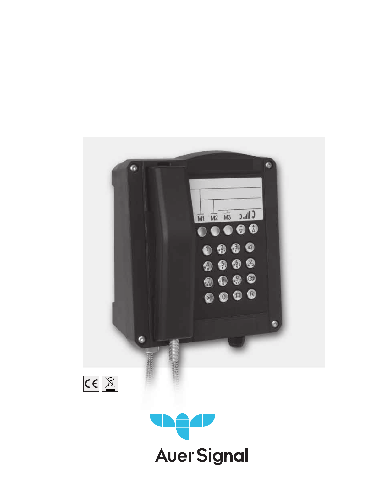
Explosion-proof telephone
Operating instructions
ExSafeTel MB
dST1MB 2.0_E

2
Foreword
Our explosion-proof, weatherpoof phone offers precision, comfort,
extended service life and reliability. It is programmable and it can
withstand harsh environmental conditions. T he phone can be used
under seve re conditions including seawater, high humidity, dust and it
withstands strong mechanical shock in connection with explosion
protection. It is fitted with an indestructible keypad made of V4A steel
and an extremely robust body made of shock and impact-resistant
compress ion moulded plastic. All components used for making this
phone are resistant against lye and lubricants. T he 21 -part keypad
optimised for "use with gloves" and made of V4A steel is easy to
operate and thus meets all requirements for a modern and reliable
communications device. T he E xSafeT el MB phone offers a reliable
communication channel when connected to the public network or to
PB X systems.

3
Table of contents
General operating conditions............................................................. 5
Device Overview ................................................................................
6
Keyboard ............................................................................................ 9
Packaging Contents ........................................................................... 9
Explosion Protection - Device Description ......................................... 10
Explosion Protection - Device Construction....................................... 11
Explosion Protection - Indicators........................................................ 14
Explosion Protection - Identification................................................... 15
Assembly and Installation................................................................ .. 16
Connection Plan................................................................................. 17
Loop Bracket ..................................................................................... 17
Hole Pattern ...................................................................................... 18
Commissioning .................................................................................. 18
Maintenance....................................................................................... 18
Receiver Operation ........................................................................... 19
Open listening ................................................................................... 19
Handsfree ......................................................................................... 19
Working with the headset ................................................................ .. 20
Operation ......................................................................................... 21
Receiving calls ............................................................................ 21
Call somebody ............................................................................ 21
Redial .......................................................................................... 21
Execute queries .......................................................................... 21
Change telephone configuration................................................. 22
Signaltones ................................................................................ 22
Configuration.................................................................................... 23
Set ring tone volume ................................................................... 23
Select ring tone melody .............................................................. 23
Set receiver volume .................................................................... 23
Set speaker volume for speakers ................................................. 23
Set speake r volume for hands free ............................................. 23
Set headset volume .................................................................... 23
Save or delete telephone numbers for speed dialling buttons .... 24
Determine dialling behaviour ...................................................... 24
Save or delete line access code ................................................. 24
Determine duration of the break after dialling the line access code
24
Determine duration of the loop current disruption (flash duration)
25
Enable/disable change block ...................................................... 25
Enter PIN .................................................................................... 25
Enable/disable external speaker ................................................. 26
Restore state of delivery ............................................................. 26
State of delivery ............................................................................... 27
Technical data ................................................................................. 28

4
Directives and guidelines ................................................................ .. 31
Service ............................................................................................. 32
Care and maintenance...................................................................... 32
Disposal ........................................................................................... 32
Warning and safety notes ................................................................ 32
CE certificate ..................................................................................... 34
EU Declaration of Conformity .......................................................... 35

5
General operating conditions
1 . T he ExResistTel MB weatherproof phone can be connected to the
telephone lines of analogue exchanges.
2. T he handset is fittedwith a stray field coil for connecting hearing aid
devices. Persons wearing a hearing aid device with an inductive
receiver can directly receive the signal of the earphone.
3. T he optional external speaker can be used in ringer, open listening
and hands-free modes. T he volume of the internal speaker is
reduced when the external speaker is turned on.
4. T he phone has a receiver mount with a reed contact hook switch.
T he handset must be placed back on the mount to end the call. A
conversation is ended and a new call is started by pressing the
disconnect button on the keypad (see page 9).
5. If the you do not make a selection within 2 minutes, the exchange
can cut offthe power supply. T hen you will stop hearing the dial
tone. In this case, please place back the handset, wait for 2 seconds
and lift t
he handset again.
6. An acknowledgement tone confirms that the settings have been
stored.
7. When you receive a call, the ExSafeTelMB phone rings with the
selected volume.
8. Changing the settings can be prevented by setting a PIN number.
Forgettingthe PIN number is similar to losing a key. If you forgot the
PIN number, please contact our technical support service.
9. T here is a warranty period of 36 months from the date of purchase.
In case of any problems please contact our technical support
service in Austria, Vienna:
Telefon 0043 1 813 82 20 · Telefax 0043 1 815 99 54
http://www.auersignal.com · e-mail: offi[email protected]

6
In case of issues which cannot be solved by phone, please send the
complete device with a copy of the sales receipt to the following
address:
Auer Signal GmbH
Support E xSafeTelMB
A-1230 Vienna
If no errors are found during the inspection, we shall issue an
invoice for the processing fee.
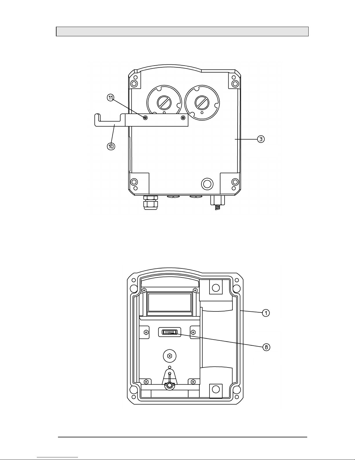
Overview of the device
(Cover screws)
(T op part of
t
he phone)
(Screws)
(Snap-in hook)
Perfektastrasse 102
7
Overview of the device
Exterior view of the lower part of the phone
Interior view of the upper part of the phone
(Screws)
(Hook)
(Top part of
the phone)
(Top part of
the phone)
(Pin
header)

8
Overview of the device
Interior view of the lower part of the phone
…
No images needed here .
Keypad
(Speaker cable)
(Reed contact
cable)
(Sealing plug)
(Cable gland)
(Sealing plug)
(Screws)
(Lower part
of the phone)
(Keypad
connector)
(Programming
interface)

9
Keypad
Package contents
T he package contains:
- T elephones E xSafeTelMB
- Operating manual
- 2 sticky label panels
- MB sticker
Label field
Volume settings buttons
for setting the volume of the
handset, speaker (hands
-
free and open conversation)
and headset during the
conversation
Speed dialling
button
Loudspeaker
button
Disconnect
button
Redial button
Second call
button
Numeric keys
1 0
E xplosion protection - device description
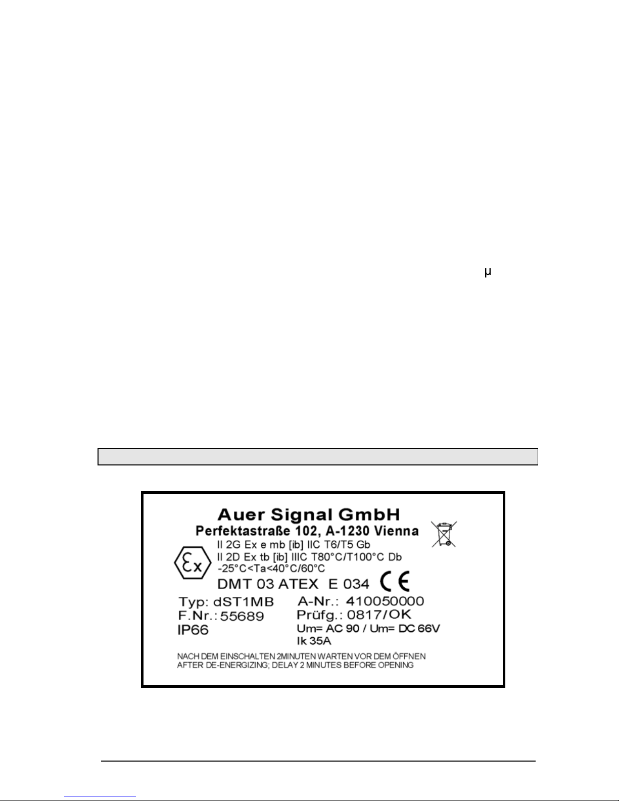
T he E xSafeT el MB serves for making calls within operating facilities in
danger of explosion in the zones : Zone 1 , Zone 2, Zone 21 and Zone
22.
T he telephone is to be realized in the following ignition protection types:
II 2G E x e mb [ib] IIC T 5 Gb E x e mb [ib] IIC T 5 Gb
II 2D E x tb [ib] IlIC T 100 °C Db E x tb [ib] IlIC T 100 °C Db
-25°C T a 60°C -25°C T a60°C
II 2G E x e mb [ib] IIC T 6 Gb E x e mb [ib] IIC T 6 Gb
II 2D E x tb [ib] IlIC T 80°C Db E x tb [ib] IlIC T 80°C Db
-25°C T a40°C -25°C T a40°C
DMT 03 ATEX E 034
T he E xSafeTel MB telephone is designated to analogue telephone
networks.
T he non-secure voltage of the telephone network is led into increased
security on the clamps 13 and 14 (A, B). In the call state, this voltage is
switched through to the clamps 15 and 16 (Bell shunt1 , Bell shunt) with
increased security. T he clamps 15 and 16 (Bell shunt1 , Bell shunt) are
designated for the connection of passive loads, e.g. a passive external,
explosion protected second alarm.
Furthermore, from the non-secure voltage of the analogue telephone
network:
a secure listener current with clamps within the telephone casing,
for the receiver connected with the telephone casing, as well as
secure circuits with clamps within the telephone casing to connect a
secure headset or optionally a secure second receiver, as well as
a secure circuit with clamps within the telephone casing for the
connection to a secure speaker.
T he headset, second receiver, external speaker and external secondary
alarm accessories are not a component of the ExSafeTel MB
telephone, but rather can be connected as an option.

1 1
E xplosion Protection – Device Construction
T he E xSafeTelMB telephone has an unpainted casing made of
electrical-static, conductive press plant material and a stainless steel
keyboard.
T he casing consists of a box shaped lower part, in which a tub is
integrated to hold the electronic system, as well as a curved cover with
a keyboard.
T he cover is pressed under the medium layer of a surrounding seal with
four screws on the casing lower part and forms the non-secure and
secure connection space. T he electronic system conductor board is
located in the tub from the casing lower part, which is completely
embedded in the compound.
Non-secure connection clamps with increased security:
From the casting, a 4-pin connection clamp series (See connection plan
on page 18 ) comes out in increased security, to connect the non-secure
telephone network (A, B), clamp 13 and 14 as well as for the connection
for an optional, external, explosion protected second alarm (Bell shunt1 ,
Bell shunt), clamp 15 an 16 .

12
Secure connection clamps:
From the casting, a 12 -pin, secure connection clamp series (see
connection plan on page 18) comes out to connect the receiver
integrated in the telephone casing, clamps 1 to 4, as well as the secure
accessories, clamps 5 to 12.
The clamps 7 and 8 are intended for the connection of dynamic
earphones, as used in second receiver and headsets. This output is
therefore optionally used to connect a second receive or a headset, this
means second receivers and headsets cannot be connected
simultaneously as accessories.
Clamp Note Usage
1
Dynamic earphone connection 1
Earphone ear piece
2
Dynamic earphone connection 2
3
Electret microphone connection (+)
Earpiece microphone
4
Electret microphone connection (-)
5
Electret microphone connection (+)
Headset microphone
6
Electret microphone connection (-)
7
Dynamic earphone connection 1
Headset or second
receiver earphone
8
Dynamic earphone connection 2
9
Bridges between the clamps 9 and
10 r ecognize the telephone as a
connected headset
Headset recognition
10
11
Dynamic volume connection 1
External speaker
12
Dynamic speaker connection 2
To connect the accessory, the blank plugs installed in the telephone
casing are to be exchanged through suitable explosion protected cable
and line guides (M20x1.5).
Before the connection of the secure accessories, an evaluation of the
security should be executed by the raiser corresponding with the PTB
report "interconnection of nonlinear and linear security circuits", PTB-
ThEx-10, November 1999 (ISBN 3-89701-440-8), provided no system
certificate is provided for the designated interconnection.
The technical data for the evaluation of the security should be taken
from the section "explosion protection parameters“.
Further information see EN60079 -14 "electrical operating equipment for
gas explosion endangered areas" as well as EN50281 -1 -1 "electrical
operating equipment for usage in areas with flammable dust". When
operating the device in explosion dangerous areas with flammable dust,
the operator must observe EN50281 -1 -2 (IEC61241-1-2).

13
In order to hang up the secure accessories of the second receiver or
headset, a metal clamp is designated, which is only delivered together
with the headset. In order to mount the metal clamp to the telephone,
two screw sockets are placed in the ground of the casing. The metal
clamp has corresponding bores, which allows for a mounting on the
bottom of the casing through counter sunk bolts (see device overview
on page 7). Thus, the raiser must first mount this on the bottom of the
casing when using the metal clamp. After this, the wall assembly occurs.
Secure program interface
From the cast, an 8-pin, secure connecting plug comes out (14) (see
device overview on page 8). It is only used by the manufacturer for
programming purposes. The connecting plug is to be left blank.
Programming through the raiser is not permissible.
Secure strand connection tothe installed speaker
From the casting, a secure 2-pin strand line (16) (see device overview
on page 8), guided to the installed speaker. It is soldered under casting
and on the speaker.
Secure strand connection tothe reed contact
From the casting, a secure 2-pin strand line (17) (see device overview
on page 8) led to a board, on which a magnet contact (reed contact) is
found. It is soldered under casting and on the conductor board with the
magnet contact.
Secure keyboard connection
From the casting, a secure 14 -pin flat band line with connector is guided
through (7)(see device overview on page
This connector should be placed on the 14 pin pin in the casing cover
before the device is screwed down.

14
Explosion protection – parameters
1. Non - secure power circuits
1.1 Telephone network
(Clamps A/B no.: 1 3 – 14)
Maximum input voltage Um(call voltage) AC 90 V
Permissible frequency range 16...54 Hz
or
Maximum input voltage Um(supply voltage) DC 66 V
Maximum input rated current 100 mA
Maximum input short circuit current IK
35 A
(In the input of this device is a fuse
with a disconnect threshold of 35 A.)
1.2 External secondalarm: only for the connection to passive
conductors
(Clamps Bell shunt1, Bell shunt no.: 15 –16)
Maximum call voltage AC 90 V
Frequency range 16...54 Hz
or
Maximum supply voltage DC 66 V
2. Secured Circuits
2.1 Headset (microphone)
(Clamp pair HSM no.: 5 – 6)
Maximum output voltage Uo17 V
Maximum output current Io90 mA
Maximum output rating Po80 mW
Maximum external capacity Co375 nF
Maximum external inductance L o1,2 mH
2.2 Headset (earphone) or second receiver
(Clamp pair HSR No.: 7 – 8)
Maximum output voltage Uo17 V
Maximum output current Io110 mA
Maximum output rating Po190 mW
Maximum external capacity Co375 nF
Maximum external inductance L o1,2 mH
1 5
2.3 Headset (recognition)
(Clamp pair HSS No.: 9 – 10 )
Maximum output voltage Uo1 7 V
Maximum output current Io8 mA
Maximum output rating Po33 mW
Maximum external capacity Co375 nF
Maximum external inductance L o10 0 mH
2.4 E xternal speaker
(Clamp pair SPK No.: 11 – 12 )
Maximum output voltage Uo6,6 V
Maximum output current Io250 mA
Maximum output rating Po370 mW
Maximum external capacity Co22 F
Maximum external inductance L o0,3 mH
2.5 All secure output circuits have a linear
output response curve.
3. A mbient temperature range Ex e mb [ib] IIC T5 Gb
Ex tb [ib] IIIC T100°C Db
-25°C ≤ Ta ≤ 60°C
Ex e mb [ib] IIC T6 Gb
Ex tb [ib] IIIC T80°C Db
-25°C ≤ Ta ≤ T40°C
-25°C < T a < 60°C for the temperature class T 5
-25°C < T a < 40°C for the temperature class T 6
E xplosion protection identification
Figure identification plate
T elephone type E xR esistT el MB

16
Assembly and installation
The device can be installed only on a solid and vertical wall. Loosen the
screws of the cover (2) (see the overview of the device on page 6 to 8) and
take offthe top part of the phone (1). When using the optional accessories:
headset or second headset, mount the hook (10) with two screws (11 ) on
the rear side of the lower part of the phone (In case of the above
accessories, the hook and the screws and also in case of all optional
accessories the cable gland is included in the respective package). Insert
four screws with a head diameter of 10 to 13 cm in the opening (20) and
mount the lower partof the phone (3) on the wall or a panel.
Insert the phone wire through the cable gland (4)and connect it to the
clamps 13 and 14 (A, B) according to the wiring plan. Only use wires with
an outer diameter of 5 to 9 mm, the IP66 rating of the device cannot be
otherwise guaranteed.
Connecting the secondary sounder (for W conductor) (optional
accessory)
Remove the sealing plug (5) and screw in the M20x1.5 cable gland
completely. Insert the wire of the secondary sounder through the cable
gland and connect it to the clamps 15 and 16 (Bell shunt 1, Bell shunt)
according to the wiring plan. Only use wires with an outer diameter of 5
to 9 mm, the IP66 rating of the device cannot be otherwise guaranteed.
Connecting the speaker (optional accessory)
Remove the sealing plug (6) and screw in the M20x1.5 cable gland
completely. Insert the wire of the speaker through the cable gland and
connect it to the clamps 11 and 12 (SPK+, SPK -) according to the wiring
plan. Only use wires with an outer diameter of 5 to 9 mm, the IP66 rating
of the device cannot be otherwise guaranteed.
Connecting the headset (optional accessory)
Remove the sealing plug (6) and screw in the M20x1.5 cable gland
completely. Insert the cable with the headset socket (included in the
package of the FHF headset) through the cable gland and connect it to
clamps 5 to 10 (HSM+, HSM -, HSR+, HSR -, HSS1, HSS2) according to
the wiring plan. Only use the cable included in the package of the
headset, because the IP66 rating of the device cannot be guaranteed.
Connecting the second headset (optional accessory)
Remove the sealing plug (6) and screw in the M20x1.5 cable gland
completely. Insert the wire of the second headset through the cable
gland and connect it to the clamps 7 and 8 (HSR+, HSR -) according to
the wiring plan.

17
Check the correct position of the cover seal prior to assembly. Connect the
ribbon cable with the connector ( 7) to the pin header(8) in the upper part of
the device. Mount the upper part of the phone and fasten it with four cover
screws (2) to the lower part of the phone.
When optional accessories are removed, close the openings created with
the EEx e II certified sealing plugs.
Wiring diagram
Support hook
The support force for holding the handset is infinitely adjustable.
Loosen the screws ( 12 ) and slide the snap-in hook (13). If you slide the
snap-in hook together, the support force increases, if you slide them
apart, the force decreases. Tighten the screws again.
Handset
Second
ea
rpiece
Handset
External loudspeaker
Telephone -network lines
External second ringer
y
e
g
n
w
h
b
r
1 8
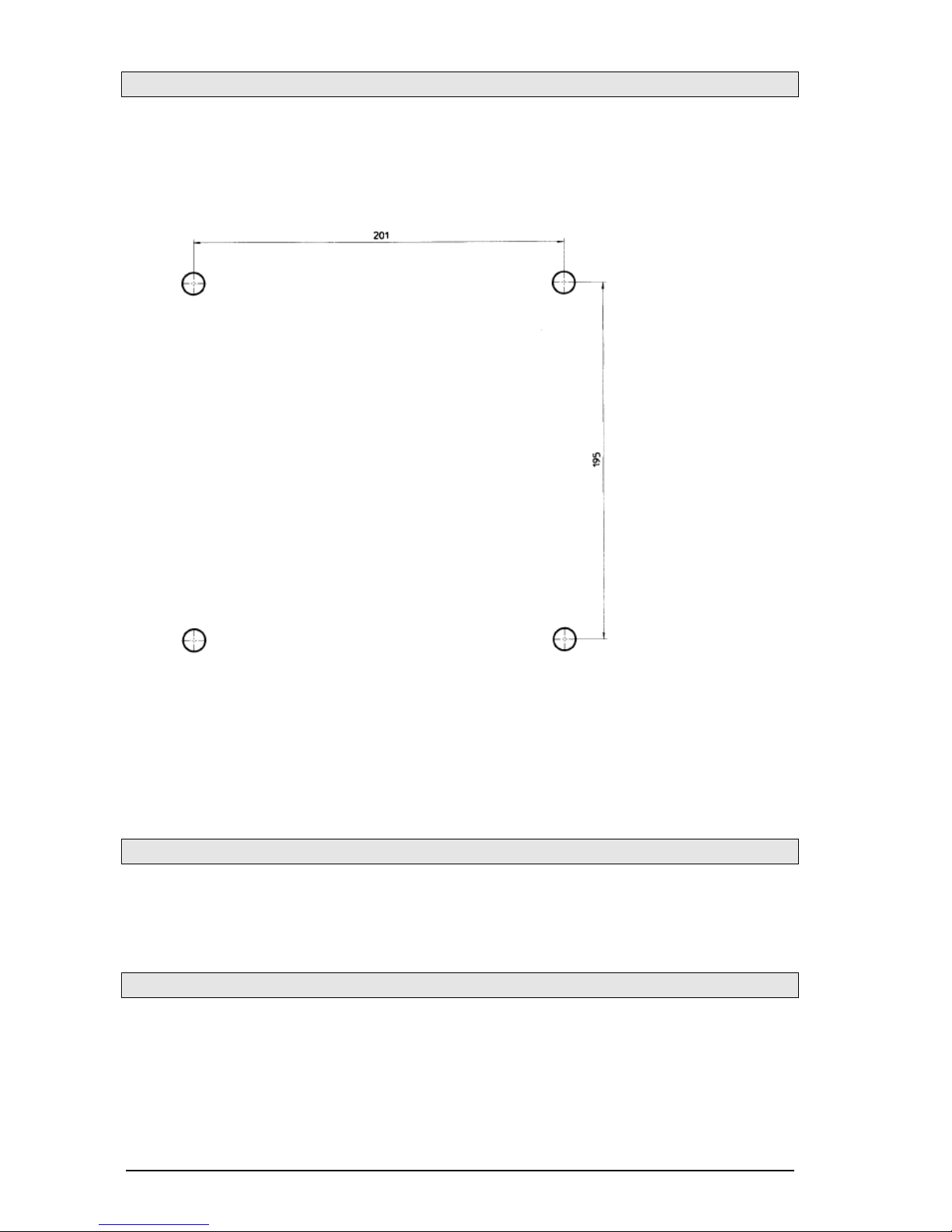
Hole pattern
Please use the following dimensions (in millimetre) for making a drilling
template:
T he diameter of the hole depends on the screws used (max. screw
diameter 8 mm) and the type of the surface (steel, wood, concrete,
sheetrock etc.) and please select accordingly.
Putting into service
T he E xSafeT el MB phone is ready for operation immediately after
connecting it to the network.
Maintenance
T he E xSafeT el MB phone does not contain any components requiring
maintenance.

1 9
Handset operation
If you lift the handset, the phone starts in handset mode. You can
modify the handset volume for the conversation using the and
buttons. For a permanent modification of the handset volume, please
access the configuration of the phone (see page 24). You can switch to
open listening with the button. Hold down the button and put the
handset back to switch to hands-free mode.
Open listening
You can modify the volume for open listening using the and
buttons. For a permanent modification of the speaker volume, please
access the configuration of the phone (see page 24). T he handset
volume cannot be modified in open listening mode. You can switch to
handset mode with the button. Hold down the button and put the
handset back to switch to hands-free mode.
Hands-free mode
If you turn on the E xSafeT el MB phone with the button, it starts up
in hands-free mode. You can modify the speaker volume of the
conversation using the and buttons. For a permanent
modification of the speaker volume, please access the configuration of
the phone (see page 24). You can end the conversation with the
button. If you lift the handset, the phone switches to handset mode.

20
Using the headset
If the headset is connected, the phone switches from open conversation
to headset mode. Open conversation is therefore not possible with the
headset. If you turn on the E xSafeT el MB phone with the button, it
starts up in headset mode. If you lift the handset in the headset mode,
the handset is given priority. This means that you can listen and speak
using the handset, and you can only listen with the headset.
Compare the operation without and with the headset connected:
Operation without the headset
Operation with the headset
Handset operation
Handset operation with the
headset
- Handset is used for speaking and
listening
- headset is used for listening only
- Speaker is turned off
Open listening
Open listening with the headset
- Handset is used for speaking and
listening
- headset is used for listening only
- Speaker is turned on
Hands-free mode
Headset mode
- Handset is placed back
- headset is used for speaking
and listening
- Speaker is turned off
You can modify the headset volume of the conversation using the
and buttons. For a permanent modification of the headset volume,
please access the configuration of the phone (see page 24). You can
end the conversation with the button.
You can specify the operation of the E xSafeT el MB phone after
disconnecting the headset in the configuration.
Table of contents
Other Auer Signal Telephone manuals


