Tadiran Telecom EMERALD ICE User manual

Emerald ICE
Digital Key
Telephone System
TM
Quick Installation Guide

The information contained in this document is proprietary and is subject to all relevant
copyright, patent and other laws protecting intellectual property, as well as any specific
agreement protecting TADIRAN TELECOM, INC. (herein referred to as the “Manufacturer”)
rights in the aforesaid information. Neither this document nor the information contained
herein may be published, reproduced or disclosed to third parties, in whole or in part, without
the express, prior, written permission of the Manufacturer. In addition, any use of this
document or the information contained herein for any purposes other than those for which it
was disclosed is strictly forbidden.
The Manufacturer reserves the right, without prior notice or liability, to make changes in
equipment design or specifications.
Information supplied by the Manufacturer is believed to be accurate and reliable. However, no
responsibility is assumed by the Manufacturer for the use there of nor for the rights of third
parties which may be affected in any way by the use thereof.
Any representation(s) in this document concerning performance of the Manufacturerʹs
product(s) are for informational purposes only and are not warranties of future performance
either express or implied. The Manufacturerʹs standard limited warranty, stated in its sales
contract or order confirmation form, is the only warranty offered by the Manufacturer in
relation thereto.
This document may contain flaws, omissions or typesetting errors; no warranty is granted nor
liability assumed in relation thereto unless specifically undertaken in the Manufacturerʹs sales
contract or order confirmation. Information contained herein is periodically updated and
changes will be incorporated into subsequent editions. If you have encountered an error,
please notify the Manufacturer. All specifications are subject to change without prior notice.
© Copyright by TADIRAN TELECOM, INC., 2004.
All rights reserved worldwide.

FEDERAL COMMUNICATIONS COMMISSION RULES
PART 68 COMPLIANCE STATEMENT
This equipment complies with Part 68 of the FCC rules. On the left side of the interior
card frame (Coral I-S, Coral I, and Coral II systems); or inside the rear doors on the
left side of the cabinet frame (Coral III cabinets) of this equipment is a label that
contains, among other information, the FCC registration number and ringer
equivalence number (REN) for this equipment. If requested, this information must be
provided to the telephone company.
The REN is used to determine the quantity of devices which may be connected to the
telephone line. Excessive REN’s on the telephone line may result in the devices not
ringing in response to an incoming call. In most, but not all areas, the sum of the
REN’s should not exceed five (5.0). To be certain of the number of devices that may
be connected to the line, as determined by the total REN’s contact the telephone
company to determine the maximum REN for the calling area.
An FCC compliant telephone cord and modular plug is provided with this equipment.
This equipment is designed to be connected to the telephone network or premises
wiring using a compatible modular jack which is Part 68 compliant.
This equipment cannot be used on telephone company-provided coin service.
Connection to Party Line Service is subject to state tariffs.
If this equipment causes harm to the telephone network, the telephone company will
notify you in advance that temporary discontinuance of service may be required. If
advance notice is not practical, the telephone company will notify the customer as
soon as possible. Also, you will be advised of your right to file a complaint with the
FCC if you believe it is necessary.
The telephone company may make changes in its facilities, equipment, operations, or
procedures that could affect the operation of the equipment. If this happens, the
telephone company will provide advance notice in order for you to make the
necessary modifications in order to maintain uninterrupted service.
If trouble is experienced with this equipment, please Contact Tadiran Telecom at:
(516) 632-7200 for repair and/or warranty information. If the trouble is causing harm to
the telephone network, the telephone company may request you remove the
equipment from the network until the problem is resolved.
The following repairs can be done by the customer: No repairs allowed.
This equipment is hearing-aid compatible.
It is recommended that the customer install an AC surge arrestor in the AC outlet to
which this device is connected. This is to avoid damaging the equipment caused by
local lightning strikes and other electrical surges.
This equipment is capable of providing user’s access to interstate providers of
operator services through the use of equal access codes. Modifications by
aggregators to alter these capabilities may be a violation of the telephone operator
consumer services improvement act of 1990 and part 68 of the FCC Rules.

FEDERAL COMMUNICATIONS COMMISSION
RADIO FREQUENCY INTERFERENCE STATEMENT
The Coral system generates, uses, and can radiate radio energy; and, if not installed in strict
accordance with this installation manual, may cause harmful interference to radio communications.
This equipment has been tested and found to comply with the limits for a Class A digital device,
pursuant to Subpart J of Part 15 of FCC Rules, which are designed to provide reasonable protection
against such interference when this equipment is operated in a commercial environment. Operation of
this equipment in a residential area is likely to cause unacceptable interference to radio and TV
reception, in which case the operator at his own expense will be required to take whatever measures
may be necessary to correct the interference.
To ensure continued compliance with specified radio energy emissions limits of FCC Rules, the
following precautions must be observed while installing and operating the equipment:
1. Install the equipment in strict accordance with the manufacturer’s instructions.
2. Verify that the power supply and associated A.C. powered equipment are connected to a
properly grounded electrical supply, and that power cords, if used, are unmodified.
3. Verify that the system grounding, including Master Ground, D.C. power system, and
equipment cabinets, is in accordance with the manufacturer’s instructions and connected to
an approved earth ground source.
4. Always replace the factory-supplied cover or keep the cabinet doors closed when not
servicing the equipment.
5. Make no modification to the equipment that would affect its compliance with the specified
limits of FCC Rules.
6. Maintain the equipment in a satisfactory state of repair.
7. Verify that emissions limiting devices, such as ferrite blocks and radio frequency
interference modules, are properly installed and functional.
If necessary the operator should consult their Supplier, Tadiran Telecom,Inc. or an experienced
radio/television engineer for additional suggestions. The following booklet prepared by the
Federal Communications Commission may be of assistance: “How to Identify and Resolve
Radio-TV Interference Problems.” This booklet is available from the U.S. Government Printing
Office, Washington, D.C. 20402, Stock No. 004-000-00345-4.

Emerald ICE Quick Installation Guide
v
Section 1-Introduction
Key System ............................................................................................................ 1-1
Section 2-System Design
Key Service Unit (KSU) ......................................................................................... 2-1
Power Supply ........................................................................................................ 2-2
Commond Control Board (CCB) .......................................................................... 2-3
610+2 (KSU1 Component) .................................................................................... 2-5
Base Board ............................................................................................................ 2-6
4SLT Board (Analog Port Module-4 Circuits)...................................................... 2-7
12EKT (Digital Port Module - 12 Circuits) ........................................................... 2-8
6CO Board (Central Office Module - 6 Circuits) ................................................. 2-9
Modem Module .................................................................................................... 2-10
4VAA Board (4-Port Voice Automated Attendant) ........................................... 2-11
Deluxe Model Telephone .................................................................................... 2-12
Standard Model Telephone ................................................................................ 2-14
DSS (Direct Station Selection Terminal) ........................................................... 2-15
Expansion Boards .............................................................................................. 2-16
System Limits/Capacities ................................................................................... 2-17
Configuration Flexibility ..................................................................................... 2-22
Section 3-Installation
System Installation ............................................................................................... 3-1
Site Planning ......................................................................................................... 3-4
KSU Initialization.................................................................................................. 3-14
Section 4-Basic Programming
Basic Programming .............................................................................................. 4-1
Accessing and Sending Modifications to the RMP ........................................... 4-7
Section 5-Programming Quick Reference Charts

vi
NOTES

Section 1-Introduction

NOTES

Emerald ICE Quick Installation Guide
Page 1-1
The Tadiran Emerald Integrated Communication Exchange, (ICE) is a versatile, Digital Hybrid Key
Telephone System that includes many advanced features. Its gateway presents several advanced
VoIP (Voice Over Internet Protocol) features. It is designed to meet the telecommunications needs
of small to medium business offices.
The Emerald ICE is a fully digital hybrid key telephone system. Utilizing “Loop Start” central office
(Telephone Company) line interfaces in conjunction with analog and digital extension ports, it pro-
vides office communications and connectivity to the Public Switched Telephone Network (PSTN).
The Emerald ICE offers a plethora of office productivity features and telephone enhancing features
that include Caller Identification (required Telephone Company subscription) in the standard pack-
age. Unlike most systems that support Caller ID, the Emerald ICE supports Caller ID to Emerald
ICE proprietary digital extensions and to third-party, Caller ID capable analog devices (cordless
telephones, etc.)
In addition to many standard features, several optional features are offered to further enhance
office communications. These built-in voice processing integration packages are:
• Automated Attendant
• Both Flash and Hard Drive Based Voicemail/Auto Attendant
The Emerald ICE platform allows the application of these voice processing platforms without loss
of valuable system port resources.
The Emerald ICE is comprised of an application-configured, expandable Key Service Unit or KSU
platform. When used with the full-featured Deluxe Telephone and its display, it provides access to
all system functions.
The Emerald ICE system architecture provides an expandable interface for digital port growth and
analog port growth. The basic configuration supports both device types. (Analog ports might be
used for plain old telephones, fax machines, modems, etc.)
Key System
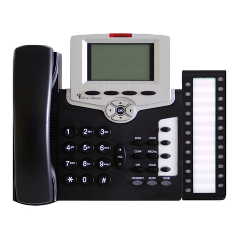
Emerald ICE KSU Emerald ICE Deluxe Model Telephone
Emerald ICE Standard Model Telephone

Section 1-Introduction
Page 1-2
The Emerald ICE incorporates state-of-the-art digital technology for voice switching and call pro-
cessing utilizing Pulse Code Modulation and Time Division Multiplexing (PCM/TDM).
The Emerald ICE is a non-blocking switch featuring no degradation of voice signals. The system
utilizes a 16-bit, 20 MHz main microprocessor and peripheral device (extensions and CO lines)
processors in a distributed processing configuration. Memory consists of 640K bytes of ROM and
384K bytes of RAM.
The Emerald ICE is shipped as follows:
1-KSU with the following:
• Ten (10) digital extension ports.
• Two (2) analog device ports.
• Six (6) CID ready CO Line ports.
• Two music source enters (can be assigned as desired to CO lines for hold music/mes-
sages.
• One power failure port (CO Line 1).
• One control contact (LBC, Gate, External Page Control).
• One external paging equipment interface.
• Two serial ports.
• PC-RMP Programming Interface.
• SMDR (Station Message Detailed Recording).
About this Manual
The Emerald ICE Quick Installation Guide is divided into the following sections:
•Section 1 - Introduction - this section provides a general description of the Emerald ICE
system as well as a description of the manual contents, associated documentation, and a
listing of the document conventions.
•Section 2 - System Design - This section provides descriptions of the individual compo-
nents of the Emerald ICE system.
•Section 3 - Basic Programming - This section provides basic instructions for accessing
the Emerald ICE programming database using both a Deluxe Model Telephone and the
RMP PC application.
•Section 4 -Programming Quick-Reference Charts - This section provides quick refer-
ence charts for all of the Deluxe Telephone programming.

Emerald ICE Quick Installation Guide
Page 1-3
Document Conventions
The following conventions are used throughout this manual.
Related Documents
The following documents should be used in conjunction with this manual:
• Emerald ICE Deluxe Model Telephone User Guide (PN 72447010146)
• Emerald ICE Standard Model Telephone User Guide (PN 72447010147)
• Emerald ICE Flash Voicemail Installation & Maintenance Manual
• Emerald ICE HD Voicemail Installation & Maintenance Manual
Convention Description
Normal Used in body text throughout this manual.
Normal, Italic Used in referencing sections, telephone features and
voice recordings or prompts.
Bold, Italic Used in describing the fields in RMP screens and other
form names or items.
Normal, Bold Used to describe filenames, device names and specific
areas of RMP menus.
Press Means to press a specific key. (e.g. press ESC means to
press and release the Escape key.)
Enter Means to type or push a button on the telephone keypad.
123
(Telephone Keys)
Indicates the keystrokes that are required to be entered on
a telephone.
Display font Indicates a display on a Deluxe Model Telephone.

NOTES

Section 2-System Design

NOTES

Emerald ICE Quick Installation Guide
Page 2-1
The Emerald ICE Key Service Unit (KSU) is designed as a modularized, flat-pack. Two KSU’s
(KSU1 and KSU2) may be equipped to attain the total system capacity of 24 CO lines, 58 Exten-
sions (46 digital and 18 analog) and 8 Voice Processing Channels. Each KSU is designed to be
mounted on the wall and is shipped with a wall mounting template. The compact KSU weighs less
than 20 pounds and is UL Listed.
If using 2 KSU’s, the first KSU, or KSU1 is factory equipped with one 610+2 Board, one CCB
(Common Control Board). The second KSU or KSU2 is factory equipped with one Base Board
module. Each KSU is a self-contained cabinet containing an internal power supply for either
117vac or 230vac operation. At the time of shipping it is set for 117vac operation. From the exterior,
with covers in place, KSU1 and KSU2 look identical, however, KSU1 contains the Common Con-
trol Board(CCB).
Key Service Unit (KSU)
Emerald ICE KSU

Section 2-System Design
Page 2-2
The power supply circuitry of the Emerald ICE incorporates a linear design AC transformer with a
choice of enter voltage taps. The transformer primary windings are shipped wired for 117vac appli-
cations. A factory provided switch alternates between 230vac and 117vac applications. The output
voltage is delivered to the 610+2 Board(in KSU1, Base Board in KSU2) for voltage regulation. All
system operation and logic voltages are produced at these boards.
Two fuses are provided on the power supply board; one for ac enter over-voltage protection and
one for DC output over-current protection. A main power switch is accessible on the side of each
KSU. In the event battery backup operation is desired the KSU power cord can be connected with
an external (ancillary) UPS (Uninterruptible Power Supply). It is the responsibility of the installer to
match the battery requirements/UPS requirement to the specific needs of the equipment owner.
Power Supply

Emerald ICE Quick Installation Guide
Page 2-3
The CCB module is equipped standard in KSU1. This board contains all circuitry required to con-
trol the fully equipped Emerald ICE. All digital voice switching and call processing data switching is
accomplished via the CCB.
The CCB has one ribbon cable connector for connection to the KSU1 610+2 board and five (5)
connector sockets for connection of the system built-in modem, voice processor and 2nd Cabinet
(KSU2). Since the CCB comes installed inside of KSU1 the CCB ribbon cable is already in place
and connected to the KSU1-610+2. Assuming the orientation of the KSU1 cabinet is installed on
the wall; the two horizontal connector sockets in the lower left corner of the CCB are for the
Modem Module. The connector socket labeled “2nd Cabinet” is for connection to the KSU2-Base
Board if that expansion is required. The remaining two connector sockets on the CCB, one at the
left side, the other at the right side are for the voice processor solution. (The voice processor solu-
tion can be any of three possible choices; 4VAA, Flash Voicemail or HD Voicemail.)
The CCB also provides the following standard connectors:
• Music Channel 1 - On Hold/Background Music Interface
• Music Channel 2 - On Hold/Background Music Interface
• Control Contact (Loud Bell or External Page Relay)
• External Paging Equipment Interface
• RMP Serial Port - for on-site database programming
• SMDR Serial Port - for connection to ancillary SMDR/Call Accounting equipment
Commond Control Board (CCB)

Section 2-System Design
Page 2-4
The CCB has two Option Strap jumpers one for database start-up (J7) and one for Music Channel
One source (internal/external) selection (JP81).
•JP7 Cold Start/Normal : JP7 is used to force load database default factory settings. This
jumper will normally never require operation after the initial power up sequence is com-
pleted. However should the need arise to return the site database to the factory settings
this jumper is used to accomplish the task.
•JP81 Internal/External: J81 is used to select the Music Channel 1 source. The Emerald
ICE provides a synthesized music source for music on hold in applications where no
music source is available. The synthesized tune is repeated. JP7 is in the “External” posi-
tion when it ships from the factory.
The CCB is equipped with a Heart-beat LED that indicates processing activity on the PCB. (The
610+2 peripheral processor is operating when the Heartbeat LED is flashing.) The KSU1 operation
LED (located next to the power switch) is tied to the CCB Heartbeat LED. Therefore, when the
LED next to the power switch is flashing, the CCB is active.

Emerald ICE Quick Installation Guide
Page 2-5
The 610+2 is the large circuit board that is packaged inside of KSU1. The 610+2 provides inter-
face for up to 6 loop-start CO Lines, 10 Digital Extension Ports and 2 analog ports. Additionally the
610+2 regulates the 24 volt DC power from the source to produce all required logic voltages and
operations voltages. There is also a Power Failure Port located on the 610+2 that is connected to
the first CO Line circuit. Whenever power fails this port becomes active with dial tone from the CO
line connected to the first CO line port.
Each CO line circuit on the 610+2 board incorporates over-voltage protection, ring detector, loop
detector, loop/pulse-dial relay, current sink circuit, coupling/isolation transformer (impedance
600:600), hybrid circuit, CODEC & filter, polarity guard circuit and Radio Frequency noise filter.
The sixth CO Line port is equipped with CNG Fax Tone Detection circuitry. If FAX tone is detected,
the call is routed to the analog port designated as the destination for fax calls.
Each digital port (connects to Deluxe & Standard Telephones and DSS Consoles) is comprised of
a proprietary octal ASIC (Application Specific Integrated Circuit) transceiver. There are three data
channels in operation at each digital port via the octal transceiver. One channel is used for call pro-
cessing control of digital terminal functions/operations and two channels are used for the digital
voice channel requirements.
Each digital station interface is protected against circuit wiring shorts by an over-current protection
Polyswitch. The digital station circuit requires only one cable pair to operate and is not polarity
sensitive.
Physical connection of digital extensions, power failure telephones and CO lines to the 610+2
board is made through a 25 pair amphenol connector to be terminated on the MDF. (Main Distribu-
tion Frame)
610+2 (KSU1 Component)

Section 2-System Design
Page 2-6
The Base Board is unique to KSU2. It provides connecitivity with peripheral boards. Additionally
the Base Board regulates the 24 volt DC power from the source to produce all required logic volt-
ages and operations voltages.
The KSU2 operation LED (located next to the power switch) is tied to the CCB (KSU1) LED.
Therefore, when the LED next to the power switch is flashing, the CCB (KSU1) is active.
A long shielded cable is used to connect KSU2 to the CCCB inside of KSU1.
Each digital station interface is protected against circuit wiring shorts by an over-current protection
Polyswitch. The digital station circuit requires only one cable pair to operate and is not polarity
sensitive.
Base Board
Other manuals for EMERALD ICE
12
Table of contents
Other Tadiran Telecom Telephone manuals

Tadiran Telecom
Tadiran Telecom FlexSet-IP 280S User manual

Tadiran Telecom
Tadiran Telecom FlexSet-IP 280S User manual

Tadiran Telecom
Tadiran Telecom Emerald ICD Deluxe User manual

Tadiran Telecom
Tadiran Telecom EXP40 User manual

Tadiran Telecom
Tadiran Telecom T207 User manual

Tadiran Telecom
Tadiran Telecom T207M User manual

Tadiran Telecom
Tadiran Telecom Coral SeaBeam Operating and maintenance instructions

Tadiran Telecom
Tadiran Telecom Emerald User manual

Tadiran Telecom
Tadiran Telecom SLT User manual

Tadiran Telecom
Tadiran Telecom SLT User manual