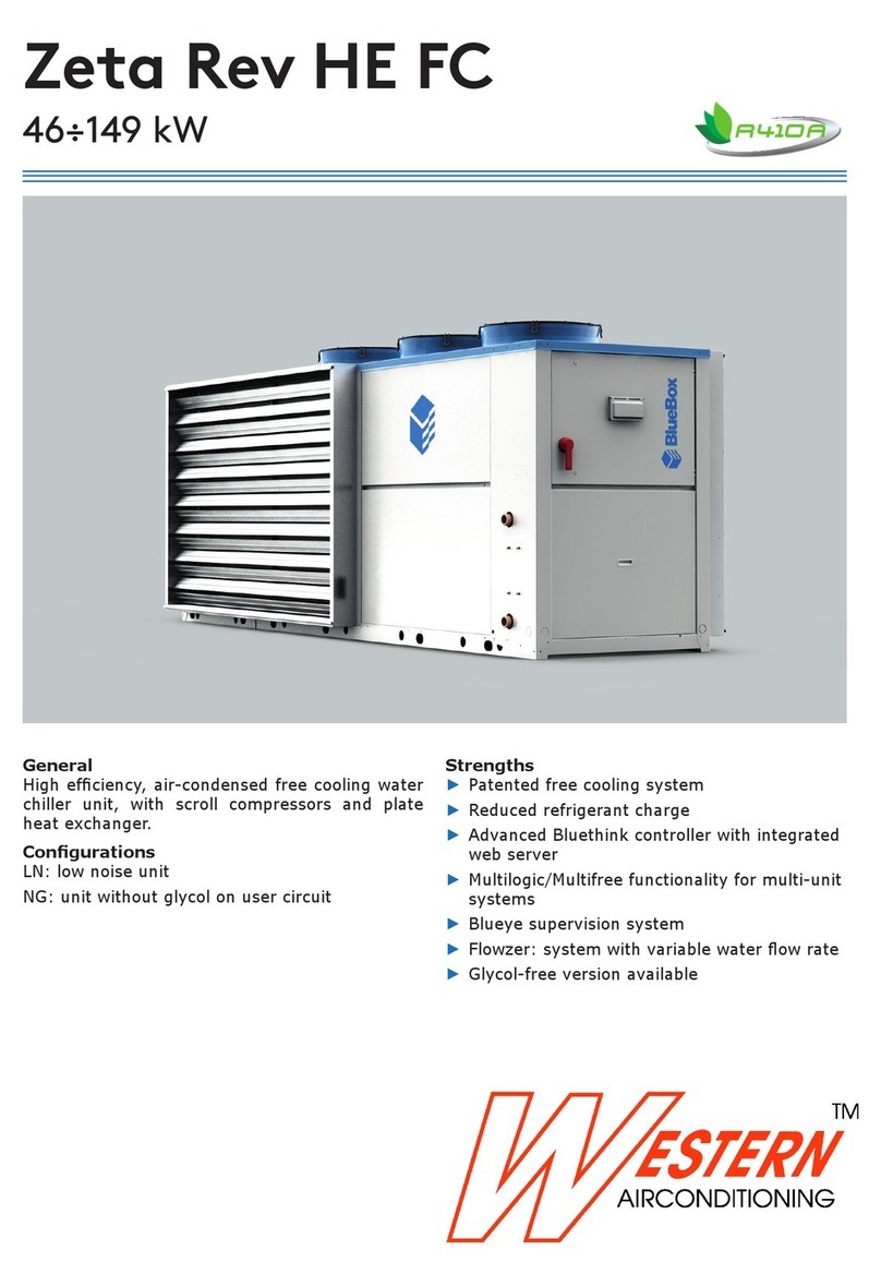
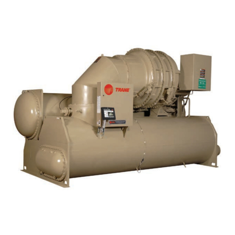
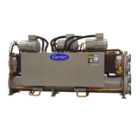
AUKS ACWCSC-960A5/MS User manual

Flooded Type Water Cooled Screw Chiller Technical Manual
Flooded Type Water Cooled Screw Chiller
Technical Manual
Central Air Conditioniner

Flooded Type Water Cooled Screw Chiller Technical Manual
Contents
Chapter I Product Selection ....................................................................................................................1
1.General ..............................................................................................................................................1
1.1 Product Overview .........................................................................................................................1
1.2 Naming Rule ................................................................................................................................3
1.3 Function .......................................................................................................................................4
2. Unit Performance ................................................................................................................................................. 5
2.1 Performance Parameter Table......................................................................................................5
2.2 Performance Parameter Table on Variable Working Condition ...................................................9
3. Unit Outline Dimension ........................................................................................................................17
Chapter II Installation and Commissioning ..............................................................................................19
1 Preparation and Tools before Installation .....................................................................................19
1.1 Preparation before Installation....................................................................................................19
1.2 Tools to be Prepared ..................................................................................................................20
2 Installation of Unit ..........................................................................................................................20
3 Connection of Water Pipeline ........................................................................................................22
3.1 Basic Requirements of Pipeline Connection .............................................................................22
3.2 Pipeline Connection of Condenser ............................................................................................23
3.3 Pipeline Connection of Evaporator ............................................................................................24
4 Electrical Wiring.............................................................................................................................26
4.1 Requirements for Power Supply.................................................................................................26
4.2 Wiring Requirements ..................................................................................................................27
5 Commissioning of Unit ..................................................................................................................28
5.1 Preparation before Commissioning ...........................................................................................28
5.2 Operation of Unit ........................................................................................................................30
Chapter III Operation and Maintenance ..................................................................................................32
1. Operation Instruction ...........................................................................................................................32
1.1 Button Instruction of Wired Controller ........................................................................................32
1.2 Operation Instruction of Wired Controller ..................................................................................33
1.2.1 Setting of Parameter ...............................................................................................................33
1.2.2 Instruction of Main Screen.......................................................................................................33
2. Maintenance ........................................................................................................................................42
2.1 Daily Maintenance ......................................................................................................................42
2.2 Regular Maintenance .................................................................................................................43
Chapter IV After-sales Service ................................................................................................................46
1. Main Parts of Unit ................................................................................................................................46
1.1 Main Pats of Cooling System .....................................................................................................46
1.2 Main Parts of Electrical System..................................................................................................49
2. Function and Control of Unit ................................................................................................................50
2.1 Function and Control of Unit.......................................................................................................50
2.2 Loading/Unloading Process Control of Unit ...............................................................................51
2.3 Protection Function ....................................................................................................................51
3. Failure Analysis and Solution ..............................................................................................................55
3.1 Analysis and Solution of Failure with Failure Code ...................................................................55
3.2 Analysis and Solution of Failure without Failure Code ..............................................................63

Flooded Type Water Cooled Screw Chiller Technical Manual
4. Failure Detection of Electrical Parts.....................................................................................................66
5. Schematic Diagram of System and Electrical Schematic Diagram .....................................................67
6. Exploded Chart and Bill of Material .....................................................................................................69

Flooded Type Water Cooled Screw Chiller Technical Manual
1
Chapter I Product Selection
1.General
1.1 Product Overview
Flooded-type water-cooled screw chiller unit has characteristics such as high efficiency ratio, compact
structure, beautiful shape, convenient operation and simple cooling system. The unit can be put into
operation immediately after simple installation, water and electricity connection, with improved
operating reliability, safety and economical efficiency of system.
Applicable places:
It is applicable to shopping mall, hospital, hotel, factory, office building, etc.
Product Characteristics:
Flooded-type dedicated compressor:
Adopted semi-hermetic twin-screw compressor and 5:6 unsymmetrical serrated structure which
realize high compression efficiency, 10% energy saving and stable operation;
Since oil level switch is above oil level, it is easy to maintain and repair;
Air suction filter has characteristics of high precision (25μm), large area and less pressure drop,
ensuring best filtering effect;
Oil filter has characteristics of high precision (10μm), large area and less pressure drop, which can
be used and set with maintenance and replacement;
Dual-layer casting wall structure effectively reduces operation noise;
Depressurized bearing housing design reduces content of refrigerant in lubricating oil entering into
bearing and can greatly prolong service life of bearing;
Screw of compressor has compact structure and low length/diameter ratio, which is hard to deform
and more efficient;
Flooded-type shell and tube heat exchanger:
Tailor-made refrigerant distributor makes temperature field of heat exchanger distribute more
evenly. Its total heat transfer coefficient is more than three times of traditional dry evaporator, so it
can transfer heat at low temperature difference, effectively improve cooling capacity and
energy/efficiency ratio of unit and save operating cost;
Chilled water flows in pipe at turbulent flow and is difficult to scale. Removable end plate is easy to
clean and service;
Wide range of cooling capacity:
Wide range of cooling capacity, which can meet different places’ requirement.
Two types: common energy efficiency and high energy efficiency can meet different demands of
users.
More reliable oil-return system:
It uses high-efficiency technology for separating oil two times to minimize oil displacement of
compressor.

Flooded Type Water Cooled Screw Chiller Technical Manual
2
It uses high-pressure injection oil return technology to ensure reliable oil-return in all working
conditions.
Accurate matching and higher energy efficiency:
Compressor provides stepless energy adjustment, which can accurately match with actual working
condition and save more energy;
Twin-compressor has parallel connection design and high seasonal energy efficiency;
Intelligent control system:
Visual Operation Control. The set information such as operating status, setting parameter and
failure alarm can reflect to controller and make easier operation and more comprehensible;
Balance control function. Unit automatically adjusts operation time of each system according to
operation status of compressor, which ensures roughly the same operation time of each system,
achieves balanced operation among multiple systems and ensures overall operation stability of
unit.
Unit can select manually or automatically ON/OFF at specified time which bring great convenience
to users. Unit can completely record the last twenty alarm records and occurrence time, providing
detailed information for after-sales maintenance;
It has complete protection function including over high pressure protection, less low pressure
protection, overload protection of compressor, superheat protection of coil, phase lost and reversal
protection, high/low voltage protection, oil level protection, high discharge temperature protection
of compressor, oil pressure difference protection of compressor, chilled water and cooling water
flow protection, overload protection of cooling tower fan and protection function for external linkage.
Multiple protection functions ensure reliable protection of unit at the first time in case of
abnormality and ensure safety of unit;
Optional remote network control function. It can be connected with communication interface of
computer or modulator through RS-485 protocol and easily connected to BAS of standard
industrial bus and public telecom switch network to monitor remote communication;

Flooded Type Water Cooled Screw Chiller Technical Manual
3
1.2 Naming Rule
Example:
ACWCSC-1180A5/MS indicates flooded-type water-cooled screw chiller unit with common energy efficiency,
one twin-screw compressor and nominal cooling capacity approximate to 345kW.
Design Revision No.: A, B, C and others follow by analog
Code of refrigerant type: code of R22 is omitted;
code of R407C is “R”;
code of R134a is “R3”;
Serial number of energy efficiency: “G” refers to unit model of high
energy efficiency and serial number of common energy efficiency is
omitted
Quantity of compressor: S stands for single compressor; D stands for
dual-compressor;
Type of evaporator: “M” refers to flooded type;
Nominal cooling capacity: figure×103W
Cooling type of condenser: “S” refers to water-cooled type;
Code of mode: no indication for single cooling;
Type of compressor: SLG-twin-screw type
Code of cooling water unit: LS

Flooded Type Water Cooled Screw Chiller Technical Manual
4
1.3 Function
Item Fuction Name Description
Protection
function
high pressure
protection shutdown when high pressure exceeds set value
low pressure protection shutdown when low pressure is lower than set value
Compressor overload
protection
shutdown when operating current of compressor exceeds max
operating current
superheat protection of
compressor winding
shutdown when winding of compressor motor exceeds a certain
temperature
high discharge
temperature protection Shutdown when discharge temperature exceeds setting value
phase sequence
protection (phase lost
and reversal)
shutdown in case of phase lost or reversal
Excessive voltage and
less voltage protection
shutdown when input voltage is morer or les than set high voltage and
low voltage value
high and low voltage
difference protection
shutdown when the difference between high voltage and low voltage is
lower than setting value
Oil pressure difference
protection
shutdown when front and rear pressure difference of oil filter of
compressor exceed set value
oil level protection of
compressor shutdown under when oil level of compressor is too low
anti-freezing protection shutdown when temperature is too low
failure protection of
temperature sensor shutdown in case of temperature sensor failure
failure protection of
pressure sensor shutdown in case of pressure sensor failure
temperature difference
protection when back
water flow
shutdown when temperature difference of cooling water exceeds set
value
temperature difference
protection when
excessive water flow
shutdown when temperature difference of cooling water is lower than
setting value
flow protection of chilled
water pump protect in case of chilled water flow lacking
flow protection of
cooling water pump protect in case of I cooling water flow lacking
Operation
function
clock display display year, month, day and time
timing ON/OFF function Set timing ON/OFF function
operating parameter
display
display inlet & outlet temperature and high & low pressure of chilled
water and cooling water
protection information
inquiry display and inquire protection information
automatic load and
unload automatically load and unload according to actual requirement
water temperature set Set water temperature within a certain range (10℃~15℃)

Flooded Type Water Cooled Screw Chiller Technical Manual
5
2. Unit Performance
2.1 Performance Parameter Table
Note of performance parameters:
1. Nominal cooling capacity of unit is tested under following working conditions:
Chilled water Inlet temperature: 12℃Outlet temperature: 7℃
Cooling water Inlet temperature of: 30℃Outlet temperature: 35℃
Fouling coefficient of evaporator: 0.0176m2./W℃
Fouling coefficient of condenser: 0.043m2./W℃
2. Noise is tested at a distance 1m front and 1.5m high of the unit. Ambient noise is lower than
30dB(A);
2.1.1 Performance Parameter Table of Unit with Common Energy Efficiency
Model ACWCS
C-960A5
/MS
ACWCS
C-1080A
5/MS
ACWCS
C-1180A
5/MS
ACWCS
C-1380A
5/MS
ACWCS
C-1570A
5/MS
ACWCS
C-1740A
5/MS
ACWCS
C-1880A
5/MS
ACWCS
C-2120A
5/MS
Cooling
capacity
kW 280 315 340 405 460 510 550 620
kcal/h×10
3241 271 297 348 396 439 473 533
Cooling
power kW 57.5 64.8 70.5 82.7 92.0 101.8 108.6 122.2
Max.
running
current
A 171 193 220 241 310 336 355 377
Power supply 380V3N~/50Hz
Compr
essor
Model semi-hermetic screw-type
Quantity (pcs) 1
Startup mode Y-△, shunt winding
Power of oil
heater (W) 300
Adjustment of
cooling
capacity
stepless adjustment
Evapo
rator
Type flooded-type evaporator
Quantity 1
Pipe diameter DN100 DN100 DN125 DN125 DN125 DN125 DN150 DN150
Cooling water
flow (m3/h) 48.2 54.2 59.3 69.6 79.1 87.7 94.6 106.6
Hydraulic
resistance
(Kpa)
44 52 55 56 57 59 59 60
Conde
nser
Type shell and tube condenser
Quantity 1
Pipe diameter DN100 DN100 DN125 DN125 DN125 DN125 DN150 DN150
Cooling water
flow (m3/h) 58.0 65.3 71.5 83.9 94.9 105.2 113.3 127.6
Hydraulic
resistance
(Kpa)
50 54 57 58 59 61 61 62
Refrig
erant
Type R22
Control mode electronic expansion valve
Unit L(mm) 3200 3200 3250 3250 3250 3500 3500 3550

Flooded Type Water Cooled Screw Chiller Technical Manual
6
dimen
sion
W (mm) 1150 1150 1150 1200 1200 1200 1300 1350
H (mm) 1500 1500 1500 1630 1670 1670 1700 1700
Opera
ting
noise
dB(A) 74 74 75 76 78 78 79 79
Unit
weight kg 1700 1830 2000 2450 2550 2850 2900 3050
Continued
Model ACWCS
C-2425A
5/MS
ACWCS
C-2730A
5/MS
ACWCS
C-3070A
5/MS
ACWCS
C-3480A
5/MD
ACWCS
C-4200A
5/MD
ACWCS
C-4845A
5/MD
ACWCS
C-5460A
5/MD
ACWCS
C-6140A
5/MD
Cooling
capacity
kW 710 800 900 1020 1230 1420 1600 1800
kcal/h×1
03610 688 774 877 1058 1221 1376 1548
Cooling
power kW 140.0 157.1 181.7 200.0 240.3 283.5 312.6 351.1
Max.
running
current
A 453 498 534 672 786 906 996 1068
Power supply 380V3N~/50Hz
Compr
essor
Model semi-hermetic screw-type
Quantity (pcs) 1 2
Startup mode Y-△, shunt winding
Power of oil
heater (W) 300
Adjustment of
cooling
capacity
stepless adjustment
Evapo
rator
Type flooded-type evaporator
Quantity 1
Pipe diameter DN150 DN150 DN150 DN200 DN200 DN250 DN250 DN250
Cooling water
flow (m3/h) 122.1 137.6 154.8 175.4 211.5 244.2 275.2 309.5
Hydraulic
resistance
(Kpa)
64 66 68 70 73 75 76 78
Conde
nser
Type shell and tube condenser
Quantity 1
Pipe diameter DN150 DN150 DN200 DN200 DN200 DN250 DN250 DN250
Cooling water
flow (m3/h) 146.2 164.6 186.0 209.8 252.8 292.9 328.9 369.9
Hydraulic
resistance
(Kpa)
66 68 70 72 75 77 78 80
Refrig
erant
Type R22
Control mode electronic expansion valve
Unit
dimen
sion
L(mm) 3550 3550 3550 4120 4180 4680 4680 4680
W (mm) 1350 1400 1400 1400 1400 1550 1550 1700
H (mm) 1850 1850 1960 2050 2050 2100 2100 2100
Opera
ting
noise
dB(A) 81 82 82 82 82 83 83 83

Flooded Type Water Cooled Screw Chiller Technical Manual
7
Unit
weight kg 3850 4300 4600 5250 6900 7500 8100 9000
2.2.2 Performance Parameter Table of Unit with High Energy Efficiency
Model ACWCS
C-960A5
/MSG
ACWCS
C-1080A
5/MSG
ACWCS
C-1180A
5/MSG
ACWCS
C-1380A
5/MSG
ACWCS
C-1570A
5/MSG
ACWCS
C-1740A
5/MSG
ACWCS
C-1880A
5/MSG
ACWCS
C-2120A
5/MSG
Cooling
capacity
kW 280 315 340 405 460 510 550 620
kcal/h×1
03241 271 297 348 396 439 473 533
Cooling
power kW 52.2 58.9 64.1 75.1 83.6 92.6 98.7 111.1
Max.
running
current
A 171 193 203 241 268 310 336 355
Power supply 380V3N~/50Hz
Comp
ressor
Model semi-hermetic screw-type
Quantity
(pcs) 1
Startup mode Y-△
Power of oil
heater (W) 300
Adjustment of
cooling
capacity
stepless adjustment
Evapo
rator
Type flooded-type evaporator
Quantity 1
Pipe diameter DN100 DN100 DN125 DN125 DN125 DN125 DN150 DN150
Cooling water
flow (m3/h) 48.2 54.2 59.3 69.6 79.1 87.7 94.6 106.6
Hydraulic
resistance
(Kpa)
44 52 55 56 57 59 59 60
Conde
nser
Type shell and tube condenser
Quantity 1
Pipe diameter DN100 DN100 DN125 DN125 DN125 DN125 DN150 DN150
Cooling water
flow (m3/h) 57.1 64.3 70.4 82.6 93.5 103.6 111.6 125.7
Hydraulic
resistance
(Kpa)
50 54 57 58 59 61 61 62
Refrig
erant
Type R22
Control mode electronic expansion valve
Unit
dimen
sion
L(mm) 3200 3200 3250 3250 3250 3250 3500 3550
W (mm) 1150 1150 1150 1200 1200 1200 1300 1350
H (mm) 1500 1500 1500 1630 1670 1670 1700 1700
Opera
ting
noise
dB(A) 74 74 75 76 78 78 79 79
Unit
weight kg 1750 1900 2100 2550 2700 2850 3000 3200

Flooded Type Water Cooled Screw Chiller Technical Manual
8
Continued
Model ACWCS
C-2425A
5/MSG
ACWCS
C-2730A
5/MSG
ACWCS
C-3070A
5/MSG
ACWCS
C-3480A
5/MDG
ACWCS
C-4200A
5/MDG
ACWCS
C-4845A
5/MDG
ACWCS
C-5460A
5/MDG
ACWCS
C-6140A
5/MDG
Cooling
capacity
kW 710 800 900 1020 1230 1420 1600 1800
kcal/h×1
03610 688 774 877 1058 1221 1376 1548
Cooling
power kW 127.2 142.9 165.1 181.8 218.5 257.7 284.2 319.1
Max.
operating
current
A 393 453 498 620 672 786 906 996
Power supply 380V3N~/50Hz
Comp
ressor
Model semi-hermetic screw-type
Quantity
(pcs) 1 2
Startup mode Y-△
Power of oil
heater (W) 300
Adjustment of
cooling
capacity
stepless adjustment
Evap
orator
Type flooded-type evaporator
Quantity 1
Pipe
diameter DN150 DN150 DN150 DN200 DN200 DN250 DN250 DN250
Cooling water
flow (m3/h) 122.1 137.6 154.8 175.4 211.5 244.2 275.2 309.5
Hydraulic
resistance
(Kpa)
64 66 68 70 73 75 76 78
Cond
enser
Type shell and tube condenser
Quantity 1
Pipe
diameter DN150 DN150 DN200 DN200 DN200 DN250 DN250 DN250
Cooling water
flow (m3/h) 144.0 162.1 183.2 206.7 249.1 288.5 324.0 364.4
Hydraulic
resistance
(Kpa)
66 68 70 72 75 77 78 80
Refrig
erant
Type R22
Control mode electronic expansion valve
Unit
dimen
sion
L(mm) 3550 3550 3550 4120 4180 4180 4680 4680
W (mm) 1350 1400 1400 1400 1400 1550 1550 1700
H (mm) 1850 1850 1960 2050 2050 2100 2100 2100
Opera
ting
noise
dB(A) 81 82 82 82 82 83 83 83
Unit
weigh
t
kg 4000 4500 4800 5400 7100 7800 8400 9300

Flooded Type Water Cooled Screw Chiller Technical M
anual
9
2.2 Performance Parameter Table on Variable Working Condition
2.2.1 Operating Range
2.2.2 Variable Working Condition Table of Unit with Common Energy Efficiency
LSSLGS280MS变工况图表
20℃
25℃
25℃
30℃
30℃
35℃
35℃
363
357
351
345
339
333
327
321
315
309
303
297
291
285
279
273
267
261
255
249
243
237
231
225
67
65
63
61
59
57
55
53
51
49
47
43
45
20℃
4 5 6 7 8 9 10
冷冻水出水温度(℃)
LSSLGS315MS变工况图表
20℃
25℃
25℃
30℃
30℃
35℃
35℃
47
49
51
53
55
57
59
61
63
65
67
69
71
73
75
77
249
255
261
267
273
279
285
291
297
303
309
315
321
327
333
339
345
351
357
363
369
375
381
387
393
399
405
20℃
4 5 6 7 8 9 10
冷冻水出水温度(℃)
Specification of Cooling Capacity All Specifications
Power supply 380V3N~/50Hz
Voltage range 342~418V
Cooling
Inlet temperature range
of cooling water 19~38℃
Outlet temperature
range of chilled water 5~15℃
Chart of Variable Working Condition o
f
ACWCSC-960A5/MS
Chart of Variable Working Condition
of ACWCSC-1080A5/MS
Cooling Capacity (Kw) Power (Kw)
Inlet temperature o
f
cooling water (
℃
)
Outlet temperature of chilled water (℃)Outlet temperature of chilled water (℃)
Inlet temperature o
f
cooling water (
℃
)
Powe
r
(Kw)
Cooling
Capacity
(Kw)

Flooded Type Water Cooled Screw Chiller Technical M
anual
10
LSSLGS345MS变工况图表
20℃
25℃
25℃
30℃
30℃
35℃
35℃
441
435
429
423
417
411
405
399
393
387
381
375
369
363
357
351
345
339
333
327
321
315
309
303
297
291
285
279
273
83
81
79
77
75
73
71
69
67
65
63
61
59
57
55
53
20℃
4 5 6 7 8 9 10
冷冻水出水温度(℃)
LSSLGS405MS变工况图表
20℃
25℃
25℃
30℃
30℃
35℃
35℃
516
507
498
489
480
471
462
453
444
435
426
417
408
399
390
127
124
121
118
115
112
109
106
97
94
91
88
85
82
79
76
73
70
67
64
61
20℃
4 5 6 7 8 9 10
冷冻水出水温度(℃)
LSSLGS460MS变工况图表
20℃
25℃
25℃
30℃
30℃
35℃
35℃
591
582
573
564
555
546
537
528
519
510
501
492
483
474
465
456
447
438
429
420
411
402
393
384
375
106
103
100
97
94
91
88
85
82
79
76
73
70
67
20℃
4 5 6 7 8 9 10
冷冻水出水温度(℃)
LSSLGS510MS变工况图表
20℃
25℃
25℃
30℃
30℃
35℃
35℃
76
79
82
85
88
91
94
97
100
103
106
109
112
115
118
411
420
429
438
447
456
465
474
483
492
501
510
519
528
537
546
555
564
573
582
591
600
609
618
627
636
645
654
20℃
4 5 6 7 8 9 10
冷冻水出水温度(℃)
Chart of Variable Working Condition
of ACWCSC-1180A5/MS
Chart of Variable Working Condition
of ACWCSC-1380A5/MS
Cooling Capacity (Kw)
Power (Kw)
Power (Kw)
Cooling Capacity (Kw)
Inlet temperature o
f
coolin
g
water
(
℃
)
Inlet temperature o
f
cooling water (
℃
)
Outlet temperature of chilled water (℃)Outlet temperature of chilled water (℃)
Power (Kw)
Power (Kw)
Cooling Capacity (Kw)
Inlet temperature o
f
cooling water (
℃
)
Inlet temperature o
f
cooling water (
℃
)
Chart of Variable Working Condition
of ACWCSC-1570A5/MS
Chart of Variable Working Condition
of ACWCSC-1740A5/M

Flooded Type Water Cooled Screw Chiller Technical M
anual
11
LSSLGS550MS变工况图表
20℃
25℃
25℃
30℃
30℃
35℃
35℃
82
85
88
91
94
97
100
103
106
109
112
115
118
121
124
127
447
456
465
474
483
492
501
510
519
528
537
546
555
564
573
582
591
600
609
618
627
636
645
654
663
672
681
690
699 20℃
4 5 6 7 8 9 10
冷冻水出水温度(℃)
LSSLGS620MS变工况图表
20℃
25℃
25℃
30℃
30℃
35℃
35℃
89
93
97
101
105
109
113
117
121
125
129
133
137
141
145
501
513
525
537
549
561
573
585
597
609
621
633
645
657
669
681
693
705
717
729
741
753
765
777
789 20℃
4 5 6 7 8 9 10
冷冻水出水温度(℃)
LSSLGS710MS变工况图表
20℃
25℃
25℃
30℃
30℃
35℃
35℃
105
109
113
117
121
125
129
133
137
141
145
149
153
157
161
165
573
585
597
609
621
633
645
657
669
681
693
705
717
729
741
753
765
777
789
801
813
825
837
849
861
873
885
897
909
20℃
4 5 6 7 8 9 10
冷冻水出水温度(℃)
LSSLGS800MS变工况图表
20℃
25℃
25℃
30℃
30℃
35℃
35℃
1017
1005
993
981
969
957
945
117
121
125
129
133
137
141
145
149
153
157
161
165
169
173
177
181
185
189
645
657
669
681
693
705
717
729
741
753
765
777
789
801
813
825
837
849
861
873
885
897
909
921
933
20℃
4 5 6 7 8 9 10
冷冻水出水温度(℃)
Chart of Variable Working Condition
of ACWCSC-1880A5/MS
Chart of Variable Working Condition
of ACWCSC-2120A5/MS
Outlet temperature of chilled water (℃)Outlet temperature of chilled water (℃)
Power (Kw)
Power (Kw)
Cooling Capacity (Kw)
Inlet temperature o
f
coolin
g
water
(
℃
)
Inlet temperature o
f
cooling water (
℃
)
Chart of Variable Working Condition
of ACWCSC-2425A5/MS
Chart of Variable Working Condition
of ACWCSC-2730A5/MS
Inlet temperature o
f
cooling water (
℃
)
Inlet temperature o
f
cooling water (
℃
)
Outlet temperature of chilled water (℃)Outlet temperature of chilled water (℃)
Power (Kw)
Power (Kw)
Cooling Capacity (Kw)

Flooded Type Water Cooled Screw Chiller Technical M
anual
12
LSSLGS900MS变工况图表
20℃
25℃
25℃
30℃
30℃
35℃
35℃
1146
137
142
147
152
157
162
167
172
177
182
187
192
197
202
207
212
726
741
756
771
786
801
816
831
846
861
876
891
906
921
936
951
966
981
996
1011
1026
1041
1056
1071
1086
1101
1116
1131 20℃
4 5 6 7 8 9 10
冷冻水出水温度(℃)
LSSLGS1020MD变工况图表
20℃
25℃
25℃
30℃
30℃
35℃
35℃
1293
1275
1257
1239
1221
1203
1185
1167
1149
1131
1113
1095
1077
1059
1041
1023
1005
987
969
951
933
915
897
879
861
843
825
807
235
229
223
217
211
205
199
193
187
181
175
169
163
157
151
20℃
4 5 6 7 8 9 10
冷冻水出水温度(℃)
LSSLGS1230MD变工况图表
20℃
25℃
25℃
30℃
30℃
35℃
35℃
1581
1557
1533
1509
1485
1461
1437
1413
1389
1365
1341
1317
1293
1269
1245
1221
1197
1173
1149
1125
1101
1077
1053
1029
1005
981
285
277
269
261
253
245
237
229
221
213
205
197
189
181
173
20℃
4 5 6 7 8 9 10
冷冻水出水温度(℃)
LSSLGS1420MD变工况图表
20℃
25℃
25℃
30℃
30℃
35℃
35℃
1725
1701
1677
1653
1629
1605
1581
1557
1533
1509
1485
1461
1437
1413
1389
1365
1341
1317
1293
1269
1245
1221
1197
1173
1149
1125
333
325
317
309
301
293
285
277
269
261
253
245
237
229
221
213
1749
1773
1797
1821
20℃
4 5 6 7 8 9 10
冷冻水出水温度(℃)
Chart of Variable Working Condition
of ACWCSC-3070A5/MS
Chart of Variable Working Condition of
ACWCSC-3480A5/MD
Inlet temperature o
f
cooling water (
℃
)
Inlet temperature o
f
cooling water (
℃
)
Outlet temperature of chilled water (℃)Outlet temperature of chilled water (℃)
Power (Kw)
Cooling Capacity (Kw)
Cooling Capacity (Kw) Power (Kw)
Cooling Capacity (Kw)
Cooling
Capacity
(Kw)
Powe
r
(Kw)
Power (Kw)
Outlet temperature of chilled water (℃)Outlet temperature of chilled water (℃)
Inlet temperature o
f
cooling water (
℃
)
Inlet temperature o
f
cooling water (
℃
)
Chart of Variable Working Condition
of ACWCSC-4200A5/MD
Chart of Variable Working Condition
of ACWCSC-4845A5/MD

Flooded Type Water Cooled Screw Chiller Technical M
anual
13
LSSLGS1600MD变工况图表
20℃
25℃
25℃
30℃
30℃
35℃
35℃
2031
2001
1971
1941
1911
1881
1851
1821
1791
1761
1731
1701
1671
1641
1611
1581
1551
1521
1491
1461
1431
1401
1371
1341
1311
1281
377
367
357
347
337
327
317
307
297
287
277
267
257
247
237
227
20℃
4 5 6 7 8 9 10
冷冻水出水温度(℃)
LSSLGS1800MD变工况图表
20℃
25℃
25℃
30℃
30℃
35℃
35℃
2301
2265
2229
2193
2157
2121
2085
2049
2013
1977
1941
1905
1869
1833
1797
1761
1725
1689
1653
1617
1581
1545
1509
1473
1437
421
409
397
385
373
361
349
337
325
313
301
289
277
265
20℃
4 5 6 7 8 9 10
冷冻水出水温度(℃)
2.2.3 Variable Working Condition Table of Unit with High Energy Efficiency
LSSLGS280MSG变工况图表
20℃
25℃
25℃
30℃
30℃
35℃
35℃
354
354
347
340
333
326
319
312
305
298
291
284
277
270
263
256
249
242
235
228
61
59
57
55
53
51
49
47
43
41
39
45
37
20℃
4 5 6 7 8 9 10
冷冻水出水温度(℃)
LSSLGS315MSG变工况图表
20℃
25℃
25℃
30℃
30℃
35℃
35℃
403
396
389
382
375
368
361
354
347
340
333
326
319
312
305
298
291
284
277
270
263
256
69
67
65
63
61
59
57
55
53
51
49
47
43
45
20℃
4 5 6 7 8 9 10
冷冻水出水温度(℃)
Chart of Variable Working Condition
of ACWCSC-5460A5/MD
Chart of Variable Working Condition
of ACWCSC-6140A5/MD
Outlet temperature of chilled water (℃)Outlet temperature of chilled water (℃)
Power (Kw)
Power (Kw)
Cooling Capacity (Kw)
Inlet temperature o
f
cooling water (
℃
)
Inlet temperature o
f
cooling water (
℃
)
Chart of Variable Working Condition
of ACWCSC-960A5/MSG
Outlet temperature of chilled water (℃)Outlet temperature of chilled water (℃)
Inlet temperature o
f
cooling water (
℃
)
Inlet temperature o
f
cooling water (
℃
)
Chart of Variable Working Condition
of ACWCSC-1080A5/MSG
Cooling Capacity (Kw) Power (Kw)
Powe
r
(Kw)
Cooling
Capacity
(Kw)

Flooded Type Water Cooled Screw Chiller Technical M
anual
14
LSSLGS345MSG变工况图表
20℃
25℃
25℃
30℃
30℃
35℃
35℃
445
438
431
424
417
410
403
396
389
382
375
368
361
354
347
340
333
326
319
312
305
298
291
284
277
75
73
71
69
67
65
63
61
59
57
55
53
51
49
47
20℃
4 5 6 7 8 9 10
冷冻水出水温度(℃)
LSSLGS405MSG变工况图表
20℃
25℃
25℃
30℃
30℃
35℃
35℃
522
515
508
501
494
487
480
473
466
459
452
445
438
431
424
417
410
403
396
389
382
375
368
361
354
347
340
333
326
87
85
83
81
79
77
75
73
71
69
67
65
63
61
59
57
55
20℃
4 5 6 7 8 9 10
冷冻水出水温度(℃)
LSSLGS460MSG变工况图表
20℃
25℃
25℃
30℃
30℃
35℃
35℃
592
585
578
571
564
557
550
543
536
529
522
515
508
501
494
487
480
473
466
459
452
445
438
431
424
417
410
403
396
389
382
375
368
97
95
93
91
89
87
85
83
81
79
77
75
73
71
69
67
65
63
61
20℃
4 5 6 7 8 9 10
冷冻水出水温度(℃)
LSSLGS510MSG变工况图表
20℃
25℃
25℃
30℃
30℃
35℃
35℃
70
73
76
79
82
85
88
91
94
97
100
103
106
411
420
429
438
447
456
465
474
483
492
501
510
519
528
537
546
555
564
573
582
591
600
609
618
627
636
645
654
20℃
4 5 6 7 8 9 10
冷冻水出水温度(℃)
Chart of Variable Working Condition
of ACWCSC-1180A5/MSG
Cooling Capacity (Kw) Power (Kw)
Outlet temperature of chilled water (℃)
Inlet temperature o
f
cooling water (
℃
)
Chart of Variable Working Condition
of ACWCSC-1380A5/MSG
Cooling Capacity (Kw) Power (Kw)
Inlet temperature o
f
cooling water (
℃
)
Outlet temperature of chilled water (℃)
Chart of Variable Working Condition
of ACWCSC-1570A5/MSG
Cooling Capacity (Kw) Power (Kw)
Inlet temperature o
f
cooling water (
℃
)
Outlet temperature of chilled water (℃)Outlet temperature of chilled water (℃)
Cooling Capacity (Kw) Power (Kw)
Inlet temperature o
f
cooling water (
℃
)
Chart of Variable Working Condition
of ACWCSC-1740A5/MSG

Flooded Type Water Cooled Screw Chiller Technical M
anual
15
LSSLGS550MSG变工况图表
20℃
25℃
25℃
30℃
30℃
35℃
35℃
73
76
79
82
85
88
91
94
97
100
103
106
109
112
115
447
456
465
474
483
492
501
510
519
528
537
546
555
564
573
582
591
600
609
618
627
636
645
654
663
672
681
690
699
708
20℃
4 5 6 7 8 9 10
冷冻水出水温度(℃)
LSSLGS620MSG变工况图表
20℃
25℃
25℃
30℃
30℃
35℃
35℃
82
85
88
91
94
97
100
103
106
109
112
115
118
121
124
127
130
498
507
516
525
534
543
552
561
570
579
588
597
606
615
624
633
642
651
660
669
678
687
696
705
714
723
732
741
750
759
768
777
786
795
20℃
4 5 6 7 8 9 10
冷冻水出水温度(℃)
LSSLGS710MSG变工况图表
20℃
25℃
25℃
30℃
30℃
35℃
35℃
93
97
101
105
109
113
117
121
125
129
133
137
141
145
149
573
585
597
609
621
633
645
657
669
681
693
705
717
729
741
753
765
777
789
801
813
825
837
849
861
873
885
897
909
20℃
4 5 6 7 8 9 10
冷冻水出水温度(℃)
LSSLGS800MSG变工况图表
20℃
25℃
25℃
30℃
30℃
35℃
35℃
1020
105
109
113
117
121
125
129
133
137
141
145
149
153
157
161
165
169
648
660
672
684
696
708
720
732
744
756
768
780
792
804
816
828
840
852
864
876
888
900
912
924
936
948
960
972
984
996
1008 20℃
4 5 6 7 8 9 10
冷冻水出水温度(℃)
Chart of Variable Working Condition
of ACWCSC-1880A5/MSG
Chart of Variable Working Condition
of ACWCSC-2425A5/MSG
Chart of Variable Working Condition
of ACWCSC-2730A5/MSG
Chart of Variable Working Condition
of ACWCSC-2120A5/MSG
Cooling Capacity (Kw)
Inlet temperature o
f
cooling water (
℃
)
Inlet temperature o
f
cooling water (
℃
)
Inlet temperature o
f
cooling water (
℃
)
Inlet temperature o
f
cooling water (
℃
)
Power (Kw)
Power (Kw)
Power (Kw) Power (Kw)
Outlet temperature of chilled water (℃)Outlet temperature of chilled water (℃)

Flooded Type Water Cooled Screw Chiller Technical M
anual
16
LSSLGS900MSG变工况图表
20℃
25℃
25℃
30℃
30℃
35℃
35℃
1152
1138
1124
1110
1096
1082
1068
121
125
129
133
137
141
145
149
153
157
161
165
169
173
177
181
185
189
193
718
732
746
760
774
788
802
816
830
844
858
872
886
900
914
928
942
956
970
984
998
1012
1026
1040
1054
20℃
4 5 6 7 8 9 10
冷冻水出水温度(℃)
LSSLGS1020MDG变工况图表
20℃
25℃
25℃
30℃
30℃
35℃
35℃
1311
1296
1281
1266
1251
137
142
147
152
157
162
167
172
177
182
187
192
197
202
207
212
816
831
846
861
876
891
906
921
936
951
966
981
996
1011
1026
1041
1056
1071
1086
1101
1116
1131
1146
1161
1176
1191
1206
1221
1236
20℃
4 5 6 7 8 9 10
冷冻水出水温度(℃)
LSSLGS1230MDG变工况图表
20℃
25℃
25℃
30℃
30℃
35℃
35℃
1579
1558
1537
163
169
175
181
187
193
199
205
211
217
223
229
235
241
247
253
259
970
991
1012
1033
1054
1075
1096
1117
1138
1159
1180
1201
1222
1243
1264
1285
1306
1327
1348
1369
1390
1411
1432
1453
1474
1495
1516
20℃
4 5 6 7 8 9 10
冷冻水出水温度(℃)
LSSLGS1420MDG变工况图表
20℃
25℃
25℃
30℃
30℃
35℃
35℃
1810
1789
1768
1747
1726
1705
1684
1663
1642
1621
1600
1579
1558
1537
193
199
205
211
217
223
229
235
241
247
253
259
265
271
277
283
289
295
301
1138
1159
1180
1201
1222
1243
1264
1285
1306
1327
1348
1369
1390
1411
1432
1453
1474
1495
1516
20℃
4 5 6 7 8 9 10
冷冻水出水温度(℃)
Chart of Variable Working Condition
of ACWCSC-3070A5/MSG
Inlet temperature o
f
cooling water (
℃
)
Power (Kw)
Cooling Capacity (Kw)
Outlet temperature of chilled water (℃)
Chart of Variable Working Condition
o
f
ACWCSC-3480A5/MDG
Chart of Variable Working Condition
of ACWCSC-4200A5/MDG Chart of Variable Working Condition
of ACWCSC-4845A5/MDG
Power (Kw)
Power (Kw)
Power (Kw)
Outlet temperature of chilled water (℃)Outlet temperature of chilled water (℃)
Outlet temperature of chilled water (℃)
Cooling Capacity (Kw)
Inlet temperature o
f
cooling water (
℃
)
Inlet temperature o
f
cooling water (
℃
)
Inlet temperature o
f
cooling water (
℃
)

Flooded Type Water Cooled Screw Chiller Technical M
anual
17
LSSLGS1600MDG变工况图表
20℃
25℃
25℃
30℃
30℃
35℃
35℃
2034
2006
213
221
229
237
245
253
261
269
277
285
293
301
309
317
325
333
1278
1306
1334
1362
1390
1418
1446
1474
1502
1530
1558
1586
1614
1642
1670
1698
1726
1754
1782
1810
1838
1866
1894
1922
1950
1978
20℃
4 5 6 7 8 9 10
冷冻水出水温度(℃)
LSSLGS1800MDG变工况图表
20℃
25℃
25℃
30℃
30℃
35℃
35℃
2286
2258
2230
2202
2174
2146
2118
2090
2062
2034
2006
237
245
253
261
269
277
285
293
301
309
317
325
333
341
349
357
365
373
1418
1446
1474
1502
1530
1558
1586
1614
1642
1670
1698
1726
1754
1782
1810
1838
1866
1894
1922
1950
1978
20℃
4 5 6 7 8 9 10
冷冻水出水温度(℃)
3. Outline Dimension of Unit
Outline and connection dimension diagram of unit – single compressor (ACWCSC-960A5/MS~ ACWCSC-3070A5/MS )
Outlet temperature of chilled water (℃)Outlet temperature of chilled water (℃)
Chart of Variable Working Condition
o
f
ACWCSC-5460A5/MDG Chart of Variable Working Condition
of ACWCSC-6140A5/MDG
Inlet temperature o
f
cooling water (
℃
)
Inlet temperature o
f
cooling water (
℃
)
Power (Kw)
Power (Kw)
Cooling Capacity (Kw)
This manual suits for next models
31
Table of contents
Popular Chiller manuals by other brands

York
York OPTIVIEW YIA D Operation manual

Diamond
Diamond GTP-10/LD INSTALLATION, USAGE AND MAINTENANCE MANUAL

Skope
Skope SK700 Operating and service manual

York
York YK installation instructions

Primax
Primax BF-R031 INSTRUCTIONS FOR THE INSTALLATION, USE AND MAINTENANCE

Welbilt
Welbilt Delfield CV5E Original instructions

Carrier
Carrier 19EA Initial Start-Up Instructions

Attila
Attila GN2 User and maintenance manual

Baltimore Aircoil Company
Baltimore Aircoil Company ICE CHILLER TSU-M Series Operating and maintenance instructions

Samsung
Samsung AG010KSV Series installation manual

Trane
Trane Airfinity XL IC140 manual

Moffat
Moffat Friginox RC50-26 datasheet