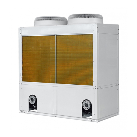
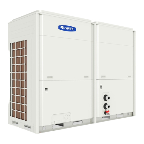
Gree LSQWF65M/N-M User manual

Air Cooled Scroll Chiller
Service Manual
(T1/R407C/50Hz)
GREE ELECTRIC APPLIANCES INC. OF ZHUHAI

1
CONTENTS
PRODUCT.......................................................................................................................................2
1 MODELS LIST ....................................................................................................................2
2 NOMENCLATURE .............................................................................................................2
3 FUNCTION ..........................................................................................................................3
4 PRODUCT DATA ................................................................................................................4
4.1 Product Data at Rated Condition.................................................................................4
4.2 Operation Range..........................................................................................................5
4.3 Electric Data................................................................................................................5
5 PIPING DIAGRAM.............................................................................................................6
5.1 Cooling Only...............................................................................................................6
5.2 Heat Pump...................................................................................................................7
CONTROL ......................................................................................................................................9
1 OPERATION FLOWCHART ............................................................................................9
1.1 Cooling Operation.......................................................................................................9
1.2 Heating Operation .....................................................................................................10
2 MAIN LOGIC ....................................................................................................................11
2.1 Cooling Mode............................................................................................................11
2.2 Heating Mode(Defrosting/ Auxiliary Electric Heater(E-heater)).........................12
2.3 Antifreezing Protection Control ................................................................................14
2.4 Control of 4-Way Valve.............................................................................................14
2.5 Control of Water Pump..............................................................................................14
3 WIRED REMOTE CONTROLLER................................................................................14
3.1 Function ....................................................................................................................14
3.2 Operation View .........................................................................................................14
3.3 Display View.............................................................................................................16
3.4 Menu Structure of Controller ....................................................................................17
3.5 Sketch map of DIP switch.........................................................................................18
INSTALLATION...........................................................................................................................20
1 BEFORE INSTALLATION ..............................................................................................20
2 INSTALLATION SITE......................................................................................................20
3 CAUTIONS FOR INSTALLATION ................................................................................20
4 MACHINE FOOTPRINT .................................................................................................20
5 DIMENSION DATA ..........................................................................................................22
6 INSTALLATION CLEARANCE DATA..........................................................................22
7 TYPICAL WATER PIPING DIAGRAM .........................................................................23
8 ANTIFREEZE....................................................................................................................24
9 ELECTRIC WIRING WORK ..........................................................................................24
9.1 Wiring Principle ........................................................................................................24
9.2 Electric Wiring Design..............................................................................................26
9.3 Wiring Diagram.........................................................................................................28
MAINTENANCE ..........................................................................................................................32

2
1 TROUBLE TABLE ............................................................................................................32
2 FLOW CHART OF TROUBLESHOOTING..................................................................33
4 EXPLODED VIEWS AND PART LIST ..........................................................................46

GREE COMMERCIAL AIR CONDITIONER AIR COOLED SCROLL CHILLER
1
PRODUCT

AIR COOLED SCROLL CHILLER PRODUCT
2
PRODUCT
1 MODELS LIST
Capacity
(kW/Ton)
Model Name
Cooling Heating
Power
Supply
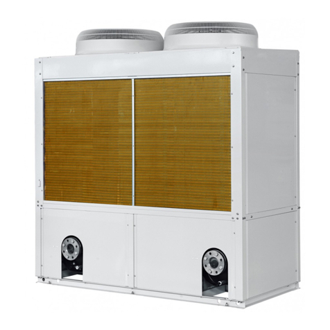
Ref. Appearance
LSQWF65M/N-M
LSQWRF65M/N-M
60/17 65/19
LSQWF80M/N-M
LSQWRF80M/N-M
76/22 80/23
LSQWF130M/N-M
LSQWRF130M/N-M
120/34 130/37
400V-
3N-
50Hz
R407C
Note:1Ton =12000Btu/h = 3.517Kw
2 NOMENCLATURE
LS QW R F 80 M / N -M
1 2 3 4 5 6 7 8
NO. Description Options
1 Water Chiller -
2 Compressors Type Hermetic Scroll Compressors
3 Function Code
Omitted-Cooling Only
R-Heat Pump
4 Air Cooled -
5 Nominal Cooling Capacity
65——60 kw
80——76kw
130——120kw
6 Modular -
7 Development series number -
8 Voltage Code
M-380V-3N-50Hz、
400V-3N-50Hz、
380~415V- 3N-50Hz

AIR COOLED SCROLL CHILLER PRODUCT
3
3 FUNCTION
Function Description
High Efficiency
Full Load Operation
Utilizing new scroll compressor technology, the chillers meet or exceed the
performance requirements of ASHRAE 90.1.All system components are selected
for optimum performance, including the condenser coil areas and evaporator
sizes.
Excellent Part
Load Performance
By using two compressors on each chiller, unloading characteristics and part load
performance are outstanding. Integrated part load value (IPLV) is a part load
performance indicator as outlined in ARI standard 550/590-1998.the IPLV rating
compress the performance of different chillers under identical conditions. When
the IPLV is listed in EER(Energy Efficiency Ratio),a higher EER will indicate
that the chiller’s overall performance is better.
Compact Design With
Small Footprint
The chillers have a reputation for a compact design and small footprint. A small
footprint can save installation costs by minimizing the size of the concrete
mounting pad or reduces the amount of structural steel if the unit is mounted on
the rooftop.
Quiet Operation
The chillers are designed with quiet scroll compressors. Fans are selected for
good performance and lower sound levels. The attention to detail with sound is
critical in the design. Small issues such as refrigerant piping, supports for piping,
securing components to the structure are all important to making a quiet product.
We proudly publish our sound performance.
Superior Controls
GREE has provided the latest technology in controlling the chillers. The new
controller provides a “user friendly” environment for the operator. The control
logic is designed to provide maximum efficiency, to help provide continuing
operation in unusual operating conditions through proactive controls, and to
provide a history of conditions to aid in problem resolutions. Perhaps the greatest
benefit is the protocol for integrating with your building automation
system(BAS)

AIR COOLED SCROLL CHILLER PRODUCT
4
4 PRODUCT DATA
4.1 Product Data at Rated Condition
LSQWF__M/N-MCooling
Only 65 80 130
LSQWRF__M/N-M
Models
Heat
Pump 65 80 130
kW 60 76 120
Cooling
Ton 17 22 34
kW 65 80 130
Nominal
Capacity
Heating
Ton 19 23 37
Cooling kW 22.6 28.7 45.3Power
Input Heating kW 21.7 26.7 43.3
Power Supply 400V-3N-50Hz
Running Control Microcomputer Auto Control;
Running Status Display; Abnormal Status Alarm
Safeties
High-Low Pressure Protection; Discharge Temp Protection;
Motor Overload Protection; Anti-freeze Water Flow Protection;
Low Water Flow Protection; Phase Sequence Protection;
Compressor Overload Protection; Compressor Inset Protection;
Presure Differential Protection;
Compressor Type Hermetic Scroll Compressors
Refrigerant Type R407C
m3/h 10.3 13.1 20.6Water
Flow GPM 45.4 57.7 90.7
Pressure
Drop kPa 10 15 17.5
Heat Exchanger Shell and Tube Evaporator
Max.
Pressure MPa 1
Cooler
Water
In/Out Pipe
Diameter
mm DN65 DN65 DN80
Heat Exchanger Finned Coil Type Condenser
Condenser Fan Motor
Power Input kW 1.15×2 1.15×2 0.75×4
Width mm 2110/2190 2110/2190 2410/2490
Depth mm 1100/1180 1100/1180 1900/1980
Outline/
Package
Dimension Height mm 2140/2140 2140/2140 2240/2240
Net Weights
(Heat Pump)kg 940 1030 1670
Operation Weights kg 1034 1133 1837

AIR COOLED SCROLL CHILLER PRODUCT
5
(Heat Pump)
Net Weights
(Cooling Only)kg 905 985 1565
Operation Weights
(Cooling Only)kg 996 1084 1722
Notes:
① Nominal capacities are based on the follow conditions:
②Parameter refer to the nameplate;
Water side Air side
Item Water flow
m3/(h·kw)
Leaving Water
℃/℉
Dry-bull temp.
℃
Wet-bull temp.
℃
Cooling 7/45 35/95 —
Heating
0.172
45/113 7/45 6/43
4.2 Operation Range
Water side Air side
Item Leaving Water
(℃/℉)
Temperature Difference
of Water(℃/℉)
Air on Condenser
(℃/℉)
Cooling
5~15℃/
41~59℉
2.5~6℃/
37~43℉
18~48℃/
64~119℉
Heating
40~50℃/
104~122℉
2.5~6℃/
37~43℉
-15~24℃/
5~75℉
4.3 Electric Data
Compressor Fan Motor Total
Model
Rated
Power
Supply Qty.
MRC
each
NRC
each
Qty.
NRC
each
MRC NRC
LSQW(R)F65M/N-M 2 31 22.1 2 2.3 66.6 48.8
LSQW(R)F80M/N-M 2 38 27.2 2 2.3 80.6 59
LSQW(R)F130M/N-M
400V-
3N-
50Hz 2 54 41.4 4 3 120 94.8
Notes:
MRC: Maximum running current (A)
NRC: Nominal running current (A)

AIR COOLED SCROLL CHILLER PRODUCT
6
5 PIPING DIAGRAM
5.1 Cooling Only
Pressure Switch
compressor
Temperature
Sensor
Filter
Thermal Expansion Valve
Temperature
Sensor
Vapour Liquid
Separato
Pressure
Switch
Temperature
Sensor
compressor
Pressure
Switch
Vapour Liquid
Separato
Temperature
Sensor
Thermal Expansion Valve
Filter
Pressure Switch
Heat Exchanger with Axial Flow Fan
Heat Exchanger with Shell and Tube
Heat Exchanger with Axial Flow Fan

AIR COOLED SCROLL CHILLER PRODUCT
7
5.2 Heat Pump
4-way valve
compressor
Pressure Switch
Check Valve
Heat Exchanger with Axial Flow Fan
Vapour Liquid
Separator
Check Valve
Liquid Tank
Filter
Thermal Expansion Valve
Temperature Sensor
Heat Exchanger with Shell and Tube
Water Outlet
Water Inlet
Temperature Sensor
Thermal Expansion Valve
Filter
Liquid Tank
Check Valve
Vapour Liquid
Separator
Pressure Switch
compressor
4-way valve
Temperature
Sensor
Check Valve
Heat Exchanger with Axial Flow Fan
Temperature
Sensor
Thermal
Expansion
Valve
Thermal
Expansion
Valve

GREE COMMERCIAL AIR CONDITIONER AIR COOLED SCROLL CHILLER
8
CONTROL

AIR COOLED SCROLL CHILLER CONTROL
9
CONTROL
1 OPERATION FLOWCHART
1.1 Cooling Operation

AIR COOLED SCROLL CHILLER CONTROL
10
1.2 Heating Operation

AIR COOLED SCROLL CHILLER CONTROL
11
2 MAIN LOGIC
2.1 Cooling Mode
In cooling mode, the four way valve is always off as long as the controller is energized and it
hasn’t anything to do with the states of compressor and fan.
Tin=T_Cin+ΔTXN
Tout=T_Cout+ΔTXN+T
Tout=T_Cout+ΔTXN+T
Tin=T_Cin+ΔTXN
(1)Control of compressor
For the module n, N=n & 0x03,ΔT=0.5,T=0.3.Compressor 1 and 2 will start and stop in fixed
time.
Compressor 1:
When Tin≥T_Cin+ΔT×N, compressor 1 is on.
WhenTout≤T_Cout+ΔT×N, compressor 1 is off.
Under other conditions, it keeps original.
Compressor 2:
When Tin≥T_Cin+ΔT×N+T, compressor 2 is on.
When Tout≤T_Cout+ΔT×N+T, compressor 2 is off.
Under other conditions, it keeps original.
(2)Control of fan
Dual-fan system
If both of the compressors are off, fan A will be off. If either of the compressor or both of them are
on, fan A will be on.
4-fan system
If compressor 1/2 is off, fan A/B will delay 30s to be off.

AIR COOLED SCROLL CHILLER CONTROL
12
If compressor 1/2 is on, fan A/B will have been on prior to 30s.
2.2 Heating Mode(Defrosting/ Auxiliary Electric Heater(E-heater))
Tin=T_Hin-ΔT×N
Tout=T_Hout-ΔT×N-T
Tin=T_Hin-ΔT×N-T
Tout=T_Hout-ΔT×N
(1)Control of compressor
For the module n, N=n & 0x03,ΔT=0.5,T=0.3.
Compressor 1:
When Tin≤T_Hin-ΔT×N, compressor 1 is on.
When Tout≥T_Hout-ΔT×N, compressor 1 is off.
Under other conditions, it keeps original.
Compressor 2:
When Tin≤T_Hin-ΔT×N-T, compressor 2 is on.
When Tout≥T_Hout-ΔT×N-T,compressor 2 is off.
Under other conditions, it keeps original.
(2)Control of fan
It is the same as that in cooling mode.
(3)Control of 4-way valve
a. For the first startup of unit from cooling mode to heating mode, the 4-way valve is
energized after compressor is on for 20s.
b. For common startup (manual or timer) of the unit in heating mode, the 4-way valve will
stop after it starts for 40s and then it restarts after the compressor is on for 20s.
c. If the compressor in heating mode is turned off at the setting temperature point, the 4-way

AIR COOLED SCROLL CHILLER CONTROL
13
valve is still energized. If the unit is turned off by operating the displayer, the 4-way valve
will be de-energized after the compressor is off for 2min.
(4)Defrosting control
Auto defrosting staring conditions (3 conditions must be met simultaneously)
a. Accumulative running time of compressor exceeds interval between the defrosting times.
b.The temperature detected by the defrosting sensor reaches defrosting start condition
c.Accumulative running time of compressor reaches 4min and 50s.
If the above 3 conditions are met simultaneously, the dual systems defrost at the same time.
d. Defrosting temperature reaches end condition. The following detailed conditions are met:
e.Defrosting time reaches setting time.
Dual-fan system
If defrosting temperature of one system (a) reaches end condition, operate according to the
following two conditions:
1)If system (b) has not reached end temperature, system (a) will be off to wait untill system
(b) reaches end condition. After that, they enter into heating operation together.
2)If system (b) also reaches end condition, both of the systems end defrosting and enter into
heating operation.
Under conditions 1) and 2), 4-way valve after defrosting to heating will firstly open and the
fan will be on after 5s.If compressor is originally on, it also keeps this state. If is originally
off, it will restart after 3-min stop at least.
4-fan system
If a certain system met the end condition, the fan will be on and then stop after 10s. After 8-s
stop of fan, if end temperature is detected again, the system directly enters into heating
operation.
(5)Auxiliary heating control
If auxiliary heating function is on by operation of displayer, the unit will control the auxiliary
electric heater on/off according to inlet water temperature.(First startup of the unit, auxiliary
electric heater will start after 15min of the unit)
If Tin ≤T1 detected by the inlet water temp. sensor, the second group of E-heater (auxiliary
electric heater) run.

AIR COOLED SCROLL CHILLER CONTROL
14
If Tin≥T2, the second group of E-heater stop.
If T1<Tin<T2, the second group of E-heater keep original state.
If Tin ≤T1+1 detected by inlet water temp. sensor, the first group of E-heater run.
If Tin≥T2+1, the first group of E-heater stop.
If T1+1<Tin<T2+1, the first group of E-heater keep original state.
If turning off control function of E-heater by display board, E-heater won’t run.
2.3 Antifreezing Protection Control
If auto antifreezing function is turned on by display board at unit off under heating mode, the unit
will have this function.
If antifreezing temp. of any module Tfi <=3.5℃(adjustable), corresponding water pump will
start.
If antifreezing temp. of any module Tfi <=1.5℃, the unit will heat with E-heater off.
If antifreezing temp. of all modules Tfi >=15℃, the unit will stop.
If antifreezing temp. of any module 1.5<Tfi <15℃, the unit will keep original state. i= 1,2.
If auto antifreezing function is turned off by display board, the unit will quit this function.
2.4 Control of 4-Way Valve
4-way valve is always off in cooling mode. Refer to 2.2 for control of 4-way valve in heating
mode.
2.5 Control of Water Pump
Water pump is open while the unit is on and it is closed after the compressor stops for some min.
Water flow switch protection means water pump is closed while the compressor stops. Refer to 2.3
for control of water pump in auto antifreezing operation.
3 WIRED REMOTE CONTROLLER
3.1 Function
One LCD can be used to control 1~8 sets of chiller in one system, it is used to display
control menu, accept and display all the parameter which is sent by main board, set the parameter,
and send the setting parameter to main board.
3.2 Operation View

AIR COOLED SCROLL CHILLER CONTROL
15
10
98
7
6
54
3
2
1
Manual Mon
Cool off 1 Modules
Cooling only
00:02
2009-01-01
NO. Name Function description
1 Power Indicator
(Green)
If the power of the display board is on, Power Indicator will
be light, or else it is off.
2 Run Indicator
(Green),
If the display board is started, Run Indicator will be lighted,
or else it won’t.
3 Error Indicator
(Red),
If the error happens, Error Indicator will be light, or else it
won’t.
4 On/Off Button
Switch on/off the control units. In the standby state, press
this button (for 3 sec) to start the unit, or press it (for 3 sec.)
to stop the unit in the operating state.
5 Reset Button
Pressing this button (for 3sec.), the screen will show
full-screen content and the error show will be eliminated, at
the same time the system will check the error again.
6 ▲Button
When selecting the menu, press this button to move a cursor
upward or left. When modifying the data, press this button
to add the numerical value.
7 ▼Button
When selecting the menu, press this button to move a cursor
downward or right. When modifying the data, press this
button to decrease the numerical value.
8 Exit Button Press this button to return to the previous menu.
9 Confirm Button
When selecting the menu, press this button to confirm the
selection and go into the next menu; When modifying the
parameters, press this button to confirm the parameter and
move the cursor.
10 LCD The area for the information display.

AIR COOLED SCROLL CHILLER CONTROL
16
3.3 Display View
6
5
4
3
2
1
Manual Mon
Cool off 1 Modules
Cooling only
00:022009-01-01
No. Display type Content description
1 Date Display the current data
2 Unit name Display the name of the unit
3 Run state Display the current state of the unit, such as running or off
4 On/off mode Display the mode of the unit on or off, such as manual or
timer
5 Module number Display the module number of the whole unit, it would be
from 0 to 8
6 Week Display the week at the moment, such as mon.

AIR COOLED SCROLL CHILLER CONTROL
17
3.4 Menu Structure of Controller
This manual suits for next models
5
Table of contents
Other Gree Chiller manuals

Gree
Gree EVO Series User manual

Gree
Gree C Series User manual

Gree
Gree GK-C03TC1AD User manual

Gree
Gree B Series User manual

Gree
Gree LSQWRF35VM/NaA-M User manual

Gree
Gree T1/R22 User manual

Gree
Gree D Series User manual

Gree
Gree GWH07AGA-K6DNA1C User manual

Gree
Gree A Series User manual

Gree
Gree FB01 User manual
Popular Chiller manuals by other brands

Daikin
Daikin EWLP012KBW1N installation manual

York
York MILLENNIUM YK Wiring diagram

Trane
Trane RTCA 108-216 Installation and operation

Trane
Trane GVAF Series Installation operation & maintenance

MTA
MTA TAEevo Tech MINI Operating and maintenance manual

aquatherm
aquatherm AT-5000 Installation, use & care manual