Western Zeta Rev HE FC User guide

Zeta Rev HE FC
46÷149 kW
General
High efciency, air-condensed free cooling water
chiller unit, with scroll compressors and plate
heat exchanger.
Congurations
LN: low noise unit
NG: unit without glycol on user circuit
Strengths
►Patented free cooling system
►Reduced refrigerant charge
►Advanced Bluethink controller with integrated
web server
►Multilogic/Multifree functionality for multi-unit
systems
►Blueye supervision system
►Flowzer: system with variable water ow rate
►Glycol-free version available


1
Application and operating principle 3
Zeta Rev HE FC
Product description 5
Description of accessories 8
Refrigerant circuit accessories 8
Fan accessories 9
Hydraulic circuit accessories 10
Electrical accessories 12
Other accessories 15
Technical specications 18
Zeta Rev HE FC 18
Zeta Rev HE FC/NG 19
Electrical specications 20
Pump data 21
User-side exchanger ow rate elds 22
Operating limits 23
Noise levels 24
Installation advice 26
Water characteristics 26
Glycol mixtures 26
Minimum water content in the system 27
Installation site 28
Installations that require the use of treated coils 29
Aeraulic head losses and options available for the ventilating section 30
Dimensional diagrams 32

2

3
APPLICATION AND OPERATING PRINCIPLE
Free cooling units meet growing demands for energy sav-
ings, since they have been designed to reduce the oper-
ating costs of refrigerating machines that work to serve
process applications or in the IT eld.
A strong point of our free cooling units is certainly the con-
trol system that allows maximum use to be made of the
free resource, consisting of outside air, so minimizing the
energy used by the compressors. The controller of the unit
activates the chiller section and the free cooling section,
also in combined mode, based on the actual external air
temperatures, the set point and the required load level.
The free cooling section is hydraulically in series with the
evaporator and this allows a benet to be obtained from
its activation even when the outside air temperature is
sufcient to carry out only a pre-cooling of the water. The
missing amount of capacity, in any case lower than the
total required, will be provided by the compressors.
As the outside air temperature goes down, the amount of
capacity that the free cooling section will be able to trans-
fer to the water will gradually increase. Consequently, the
amount of capacity that will have to be covered by the
compressors will always be lower.
When the TFT (Total Free-cooling Temperature) is reached,
the free cooling section will be able to fully meet the cool-
ing capacity requirement and therefore the compressors
can be switched off. In this condition, the unit will be able
to provide the system with a cooling capacity equal to that
required at design conditions, but with current drawn by
the fans alone.
How the unit behaves in the various scenarios is explained
briey below.
ZETA REV HE FC
Chiller only mode
When the ambient temperature is higher than the tem-
perature of the water returning from the system, all the
required cooling capacity must be produced by the com-
pressors.
In this mode, the damper that controls the air ow rate
at the free cooling coil is fully closed, whereas the one in
front of the condensing coil is fully open.
The 3-way valve bypasses the free cooling coil (to pre-
vent unnecessary head losses) and condensation control
is done, when necessary, through modulation of the fans.
Mixed mode
When the ambient temperature is lower than the tempera-
ture of the water returning from the system, the controller
activates the free cooling section.
The controller switches over the 3-way valve to put the
free cooling coil in series with the evaporator, fully opens
the free cooling damper and pushes the fans to maximum
speed. In this way, extraction of maximum cooling capac-
ity from the outside air is ensured.
The water leaving the free cooling coil will be the water
that enters the evaporator. Since the water is "pre-cooled",
the amount of capacity required of the chiller section will
be lower and therefore this will be able to operate with
reduced capacity.
Since the fans must be kept at 100% to ensure the max-
imum capacity at the water coil, condensation control is
done by modulating the opening of the damper situated in
front of the condensing coil.
Free cooling only mode
Below a certain outside air temperature, the unit operates
exclusively in free cooling mode.
The capacity given by the water coil fully meets the re-
quirement of the system, and therefore the damper in
front of the condenser is fully closed and the compressors
are kept switched off.
Also, through fan speed modulation, the controller of the
unit will manage the capacity given by the free cooling
section that, with the lowering of the outside air tempera-
ture, could be excessive.

4
ZETA REV HE FC/NG
Chiller only mode
When the ambient temperature is higher than the tem-
perature of the water returning from the system, all the
required cooling capacity must be produced by the com-
pressors.
In this mode, the damper that controls the ow rate at the
free cooling coil is fully closed, whereas the one in front of
the condensing coil is fully open.
The circulation pump on the free cooling circuit remains
switched off, whereas condensation control is done, when
necessary, through modulation of the fans.
Mixed mode
When the ambient temperature is lower than the tempera-
ture of the water returning from the system, the controller
activates the free cooling section.
The controller switches on the circulation pump of the free
cooling circuit, fully opens the free cooling damper and
pushes the fans to maximum speed. In this way, extrac-
tion of maximum cooling capacity from the outside air is
ensured.
The cooling capacity of the free cooling coil is transferred
to the system water through a decoupling exchanger. This
allows the glycol water circulating in the free cooling cir-
cuit to be separated from the system water that therefore
does not need the addition of antifreeze.
The water leaving the decoupling exchanger will be the
water that enters the evaporator. Since the water is "pre-
cooled", the amount of capacity required of the chiller sec-
tion will be lower and therefore this will be able to operate
with reduced capacity.
Since the fans must be kept at 100% to ensure the max-
imum capacity at the water coil, condensation control is
done by modulating the opening of the damper situated in
front of the condensing coil.
Free cooling only mode
Below a certain outside air temperature, the unit operates
exclusively in free cooling mode.
The capacity given by the water coil fully meets the re-
quirement of the system, and therefore the damper in
front of the condenser is fully closed and the compressors
are kept switched off.
Also, through fan speed modulation, the controller of the
unit will manage the capacity given by the free cooling
section that, with the lowering of the outside air tempera-
ture, could be excessive.

5
Zeta Rev HE FC
High efciency, air-condensed free cooling water
chiller unit, with scroll compressors and plate heat
exchanger.
PRODUCT DESCRIPTION
BODY
The structure of the unit is made of galvanized sheet-iron
coated with polyester powder in RAL 5017/7035 at 180°C,
which makes it highly resistant to weather conditions.
The structure is a load-bearing frame, with removable
panelling lined with sound absorbing expanded polyure-
thane matting.
All screws and bolts are stainless steel.
COMPRESSORS
The compressors are hermetic orbiting spiral scroll com-
pressors connected in tandem, tted with oil level sight
glass, oil equalization line, crankcase heater and electron-
ic protection.
The compressors, enclosed in a soundproof compartment
and separated from the air ow, can be accessed through
special panelling that allows maintenance operations to be
carried out even with units running.
CONDENSING COIL
The source-side exchanger is made with aluminium micro-
channel coil.
The microchannel coils are made using specic aluminium
alloys for the tubes and for the ns. This allows the effects
of galvanic corrosion to be drastically reduced to always
ensure protection of the tubes that conne the refriger-
ant. The entire coil is also subjected to SilFLUX coating
processes (or equivalent) or has zinc added to further in-
crease its corrosion resistance.
The use of microchannel coils compared to convention-
al copper/aluminium coils reduces the total weight of the
unit by about 10% and gives a reduction in refrigerant
charge of at least 30%.
Refer to chapters "Installation advice" and "Description of
accessories" for assessment of any options or treatments
based on the place of installation.
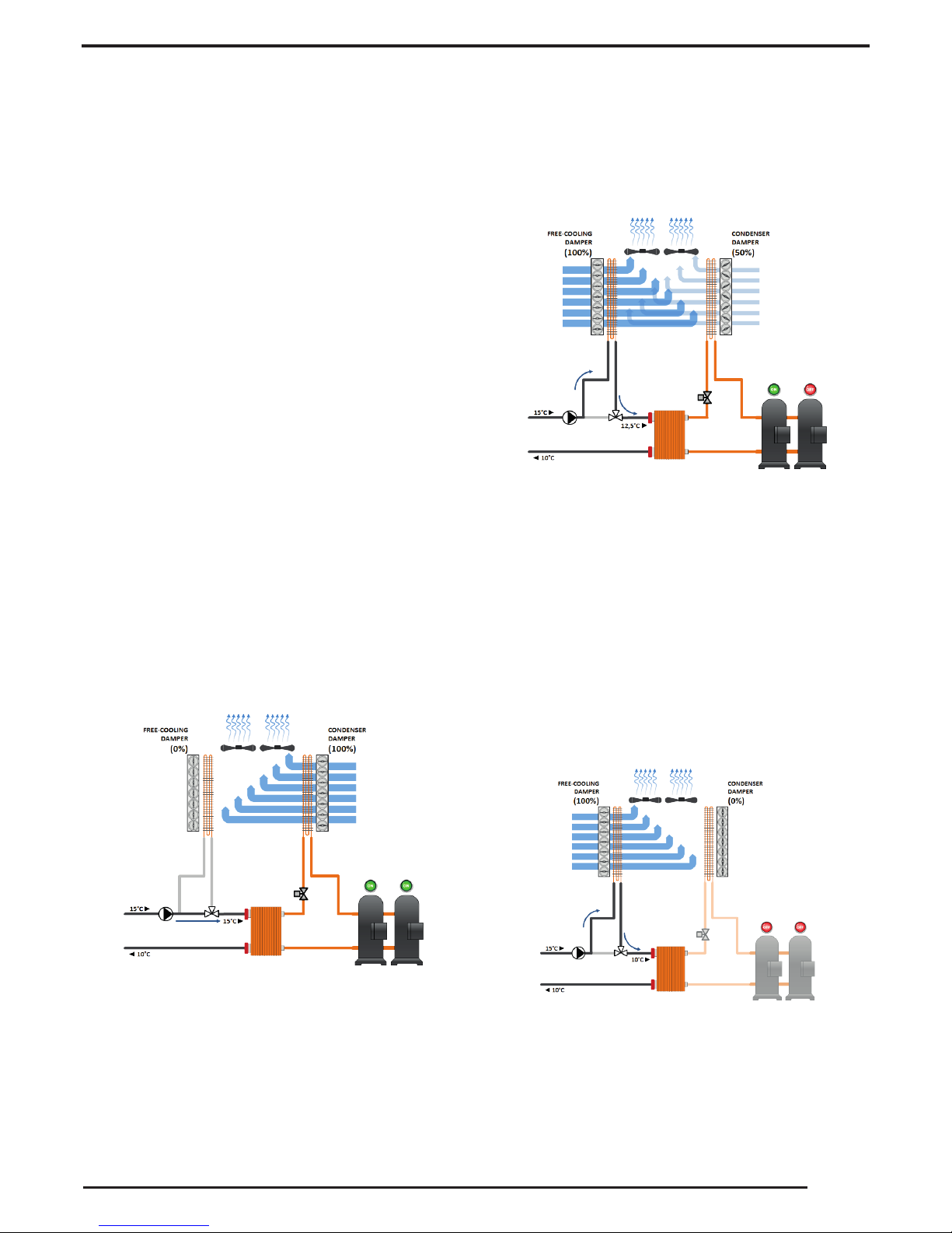
In front of the condensing coil, there is a damper dedicat-
ed to controlling the air ow rate at the exchanger, com-
plete with modulating servo control. Damper management
is done by the controller following the logics of the patent-
ed free cooling system (patent n° IT1855070):
• in chiller mode, the damper is fully open, so allowing
the maximum air ow rate, and condensation control is
carried out by adjusting the speed of the fans
• in mixed mode (chiller + free cooling) the fans operate
at full speed and condensation control is done by mod-
ulating the opening of the damper
• in free cooling mode, the damper is fully closed, so en-
suring the full ow rate at the free cooling coil alone.
FREE COOLING COIL
The free cooling exchanger consists of a row coil with cop-
per tubes and aluminium ns.
Refer to chapters "Installation advice" and "Description of
accessories" for assessment of any options or treatments
based on the place of installation.
This exchanger is put in series with the user-side heat
exchanger by means of a 3-way valve. When the unit is
not working in free cooling mode, the valve allows the
coil to be bypassed to prevent unnecessary hydraulic head
losses.
For /NG version units, the free cooling coil is connected to
a decoupling exchanger situated in series with the evapo-
rator. The coil is supplied by a dedicated circulation pump
that will be switched on only with free cooling active.
The free cooling coil is positioned on the opposite side of
the machine to the condensing coil so that it can be man-
aged completely independently.
In front of the coil, there is a damper dedicated to con-
trolling the air ow rate at the exchanger, complete with
point servo control. Damper management is done by the
controller following the logics of the patented free cooling
system (patent n° IT1855070):
• in chiller mode, the 3-way valve is closed (for the /NG
version, the circulation pump is off), the damper is fully
closed, so ensuring the full air ow rate at the condens-
ing coil alone
• in mixed mode (chiller + free cooling), the 3-way valve
is open (for the /NG version, the circulation pump is
on), the fans work at full speed and the damper is fully
open, so allowing the maximum air ow rate at the free
cooling coil
• in free cooling mode, the damper is fully open and con-
trol of the capacity given by the free cooling coil is done
by the controller of the unit by modulating the speed of
the fans
FANS
The fans are axial fans, directly coupled to a three-phase
6-pole electric motor, with integrated thermal overload
protection (klixon) and IP 54 protection rating.
The fan includes the shroud, designed to optimize its ef-
ciency and reduce noise emission to a minimum, and the
safety guard.
The fans are controlled as standard by a phase cutting
speed adjuster managed by the controller.

6
USER-SIDE HEAT EXCHANGER
The exchanger is a braze-welded stainless steel plate heat
exchanger, insulated with a shroud of closed-cell insulat-
ing material.
The exchanger is equipped with two temperature probes
(one at the inlet and one at the outlet) for controlling the
water temperature and the freeze protection.
The exchanger is protected as standard by an electric anti-
freeze heater managed by the controller of the unit.
REFRIGERANT CIRCUIT
The refrigerant circuit of the basic unit comprises:
• shut-off valve in the liquid line
• 5/16” charging valves
• liquid sight glass
• replaceable solid cartridge dehydrator lter (except for
sizes 3.2, 4.2 and 5.2 where the lter is a weld-on lter)
• thermostatic expansion valve with pressure equaliza-
tion
• high and low pressure switches
The pipes of the circuit and the exchanger are insulated
with extruded closed-cell expanded elastomer.
As an accessory, all the units can be tted with an elec-
tronic expansion valve that allows machine stability to
be reached more quickly and better superheating control
than the mechanical expansion valve, to maximize the use
of the evaporator in all load conditions.
ELECTRICAL CONTROL PANEL
The electrical control panel is made in a painted galva-
nized sheet-iron box with forced ventilation and IP54 pro-
tection rating.
The electrical control panel of the basic unit comprises:
• main disconnect switch
• automatic circuit breakers for compressors with xed
calibration
• fuses for protecting the fans and auxiliary circuits
• fan contactors
• phase-cutting fan speed adjuster
• thermal magnetic circuit breakers for pumps (if pres-
ent)
• phase monitor
• potential-free general alarm contacts
• single potential free operating contacts for compres-
sors, fans and pumps (when present)
• digital input for general ON/OFF
• external air temperature probe
• microprocessor controller with display accessible from
the outside
All the electrical cables inside the panel are numbered and
the terminal board dedicated to the customer's connec-
tions is coloured blue so that it can be quickly identied
in the panel.
Power supply: 400V/3~+N/50Hz for models from 3.2 to
10.2; 400V/3~/50Hz for models 12.2 and 13.2
CONTROL BLUETHINK
Main controller functions
The microprocessor control allows the following functions:
• water temperature adjustment, with outgoing water
control
• freeze protection
• compressor timings
• automatic rotation of compressor starting sequence
• recording of the log of all machine inputs, outputs and
states
• automatic rotation of compressor starting sequence
• recording of the alarm log
• digital input for general ON/OFF
• digital input for hot circuit ON/OFF
• Ethernet serial port with Modbus protocol and integrat-
ed web server preloaded web page
• USB port
For further details on available functions and on displayed
information, you can refer to the specic documentation
of the control.
By default, the serial connections present as standard are
enabled only for reading from BMS. Enabling of writing
from BMS is to be requested when ordering.
Main functions of the webserver
As standard, the Bluethink controller integrates a web-
server with a preloaded web page that is accessed via
password.
The web page allows the following functions to be carried
out (some of these are available only for users with ad-
vanced level rights):
• display of the main information on the unit, such as
serial n°, size, type of refrigerant
• display of the general status of the machine: water inlet
and outlet temperatures, external air temperature, op-
erating mode, evaporating and condensing pressures,
suction and discharge temperatures
• display of the status of compressors, fans, pumps, elec-
tronic expansion valves
• display in real time of the graphs of the main quantities
• display of the graphs of logged quantities
• display of alarm log
• display of the status of all the I/Os of the controller
• management of users on several levels
• remote ON/OFF
• remote set point change
• remote time band change

7
Human-Machine Interface
The control has a graphic display that allows the following
information to be displayed:
• water inlet and outlet temperature
• set temperature and differential set points
• description of alarms
• hour meter of operation and number of start-ups of the
unit, the compressors and the pumps (if present)
• high and low pressure values, and relevant condensing
and evaporating temperatures
• external air temperature
• superheating at compressor suction.
CONTROLS AND SAFETY DEVICES
All the units are tted with the following control and safety
components:
• high pressure switch with manual reset
• high pressure safety device with automatic reset, for a
limited number of occurrences, managed by the con-
troller
• low pressure safety device with automatic reset and
limited tripping managed by the controller
• high pressure safety valves
• antifreeze probe at the outlet of the user-side heat ex-
changers
• differential pressure switch already tted on the us-
er-side heat exchangers
• overtemperature protection for compressors and fans
TESTING
All the units are factory-tested and supplied complete with
oil and refrigerant.
PACKAGING
The unit is made and shipped on a wooden pallet that al-
lows the unit to be handled using a forklift truck.
The unit is wrapped in a protective transparent polyethyl-
ene stretch lm.
VERSIONS
Zeta Rev HE FC/NG
In addition to the components of the basic version, the /
NG set-up unit has:
• a water/water decoupling plate heat exchanger in place
of the 3-way valve
• a circulation pump dedicated to the free cooling circuit
(closed circuit inside the unit) with shut-off valves up-
stream and downstream of it
• a paddle ow switch to protect the free cooling circuit
• water safety valve to protect the free cooling circuit
• expansion vessel with water pressure gauge to protect
the free cooling circuit
For this version, the intermediate heat exchanger is always
in series with the user-side heat exchanger and therefore
the head losses inside the machine do not change with the
operating mode.
The use of a decoupling exchanger allows only the water
contained in the circuit inside the unit to be glycolated
and to use pure water in the system, thereby obtaining
an immediate economic saving and improving the heat
exchange on individual user points.
OPTIONS
/LN: low noise unit
In the unit with /LN option, the technical compartment
that houses the compressors is fully soundproofed with
sound absorbing material and soundproong material.
HYDRAULIC MODULES
All units can be tted with hydraulic module in various
congurations:
• /1P: hydraulic module with one pump
• /2P: hydraulic module with two pumps
• /1PS: hydraulic module with one pump and buffer tank
• /2PS: hydraulic module with two pumps and buffer tank
All the above-mentioned modules have pumps with stand-
ard discharge head.
Hydraulic modules with one pump have:
• one pump
• a gate valve on the delivery side of the pump
• an expansion vessel
Hydraulic modules with two pumps have:
• two pumps
• a check valve on the delivery side of each pump
• a gate valve on the outlet of the delivery manifold
• an expansion vessel
In the version with 2 pumps, these are always with one
on standby while the other is working. Switching over be-
tween the pumps is automatic and is done by time (to
balance the hours of operation of each one) or in the event
of failure.
Hydraulic modules with tank also have:
• a tank with drain valve and air valve

8
DESCRIPTION OF ACCESSORIES
Refrigerant circuit accessories
The "(S)" symbol indicates that the option is present as standard in the unit, provided this is not in conict with other
selected accessories.
BK Brine Kit
This accessory is compulsory if a water temperature set point lower than +3°C is used (if the unit is provided
with double set point or variable set point, the lower set point is considered).
The accessory consists of increased insulation and suitable sizing and calibration of some components.
The inlet and outlet temperatures of the user-side exchanger must be given on ordering to allow correct set-
ting of the alarm parameters and verication of the sizing of the expansion valve.
The cooling set point can then be changed by the customer in an interval that, compared to the set point given
on ordering, ranges from -1K up to the maximum temperature allowed by the above-stated operating limits.
The unit will be optimized to work at the set point temperature given on ordering. For different set points, the
cooling capacity provided and the level of efciency of the machine could decrease and move away from these
conditions.
MAFR Pressure gauges
The operating pressures of each circuit of the unit can be displayed on the control by accessing the relevant
screens. Also, the machine can be tted with pressure gauges (two for each circuit) installed in a clearly visible
position. These allow reading in real time of the working pressures of the refrigerant gas on the low pressure
side and on the high pressure side of each refrigerant circuit.
RG Fan speed adjuster (S)
The control manages the speed of the fans through a phase cutting speed governor, in order to optimize the
operating conditions and efciency of the unit.
For units equipped with EC fans, the same function is carried out using the electronically commutated motor
of the fans and is supplied as standard.
RIC Liquid receiver
The adoption of this accessory always guarantees correct feeding of the expansion valve even when the unit
is subjected to wide external air temperature ranges.
RPP Refrigerant leak detector with automatic pump down
With this accessory, a refrigerant leak detector is placed inside each compressor compartment. Detection of a
refrigerant leak is managed by the control through a specic alarm and display of a specic icon on the display
of the control. For all the circuits of the unit, the alarm also starts the machine stopping procedure with pump
down, conning all the refrigerant in the coils.
The accessory includes the capacitive backup battery.
The accessory can be applied only to units in LN or SLN set-up.
RPR Refrigerant leak detector
With this accessory, a refrigerant leak detector is placed inside each compressor compartment. Detection of
a refrigerant leak is managed by the controller through a specic alarm and display of a specic icon on the
display of the controller. This alarm stops the unit.
The accessory can be applied only to units in LN or SLN set-up.
RUB Compressor suction and delivery valves
The valves situated on the delivery side and on the suction side of the compressors allow the compressor to
be isolated from the rest of the refrigerant circuit, so making the maintenance operations quicker and less
invasive
VS Liquid line solenoid valve
This accessory prevents refrigerant migration that could damage the compressor on starting.
VTE Electronic expansion valve
The use of this component is particularly advisable on units operating in very variable heat load or operating
mode conditions, as in the case of joint management of air conditioning and high temperature water produc-
tion. The use of an electronic thermostatic valve allows you to:
• maximize heat exchange at the evaporator
• minimize response times to changes in load and operating conditions
• optimize control of overheating
• ensure maximum energy efciency

9
Fan accessories
VEC EC fans
With this accessory, EC fans, with electronically commutated brushless motor, are used for the ventilating
section. These guarantee very high efciency levels for all working conditions and allow a 15% saving on the
power absorbed by each fan working at full capacity.
Also, through a 0-10V analogue signal sent to each fan, the microprocessor carries out condensation/evapo-
ration control by continuous adjustment of the air ow rate as the external air temperature changes, with a
further reduction in electrical absorption and noise emission.
VEM Oversize EC fans
With this accessory, oversize EC fans, with electronically commutated brushless motor, are used for the ven-
tilating section. These guarantee very high efciency levels for all working conditions. Through a 0-10V ana-
logue signal sent to each fan, the microprocessor carries out condensation/evaporation control by continuous
adjustment of the air ow rate as the external air temperature changes, with a further reduction in electrical
absorption and noise emission.
Oversize EC fans allow a residual available discharge head of about 100Pa to be obtained.

10
Hydraulic circuit accessories
The "(S)" symbol indicates that the option is present as standard in the unit, provided this is not in conict with other
selected accessories.
CORM Connection for manual lling
This accessory allows the system lling procedure to be carried out directly from the unit: on the fan holder
cover, there is a 1’’ lling valve and a 1/2’’ air valve. Near the lling valve, there is also a pressure gauge for
displaying the pressure in the hydraulic circuit. This accessory can be combined only with units provided with
tank.
FVP FLOWZER VP - Inverter for manual pump adjustment
The accessory consists of inserting an inverter in the machine to manually adjust the speed of the pump (or
pumps) in order to calibrate the pump ow rate on the head losses of the system.
This accessory is to be combined with one of the integrated hydraulic modules that can be selected for the unit.
Units equipped with integrated hydraulic module allow a certain level of available discharge head (point A) to
be obtained under nominal ow rate conditions Qd.
But the actual head loss level of the system (e.g. characteristic curve R') normally causes the pump to nd a
different equilibrium point (point B), with a ow rate Qr higher than Qd.
In this condition, besides having a different ow rate from the nominal ow rate (and therefore also a different
thermal gradient), there is also higher pump power absorption.
Qr
QdQ [l/s]
n’
Qmin
n
Qmax
HAV [kPa]
n
n’
Pa [kW]
Q [l/s]
R
R’
QdQr
AB
C
A
B
C
The use of the Flowzer allows the pump speed to be set manually (e.g. at speed n' instead of n) to obtain the
design water ow rate and thermal gradient (point C).
Once the adjustment procedure has been carried out, the pump will always work at a xed ow rate.
Use of the Flowzer VP allows the power absorption of the pump to be considerably reduced with consequent
energy saving. By way of example:
• a 10% reduction in ow rate gives a reduction in absorbed power of about 23%
• a 30% reduction in ow rate gives a reduction in absorbed power of about 50%

11
FVD FLOWZER VD - Transducer for automatic adjustment
Flowzer VD requires a pressure transducer to be installed in the machine. Through this transducer, the inverter
can gauge the actual pressure at the ends of the system and automatically adapt the pump speed to obtain a
set available discharge head value. Flowzer VD must be combined with Flowzer VP.
This accessory therefore allows a constant pressure system to be achieved.
Q [l/s]
R
n’’’
n’’ n’
Qmin
n
Qmax
H
AV
[kPa]
Hd
R’
R’’
R’’’
Q’’’ Q’’ Q’ Q
Pa [kW]
Q’’’ Q’’ Q’ Q
n
n’
n’’
n’’’
Q [l/s]
With the Flowzer VD, the customer can set, directly on the inverter, the available discharge head value Hd that
the unit must maintain.
As can be seen in the graph, as the system user points close, the resistance curve of the system shifts to the
left and therefore the inverter will be able to reduce the pump speed in order to keep the available discharge
head of the unit constant. By doing so, an immediate reduction in the power absorbed by the pump will be
obtained.
The customer will have to check that, in minimum ow rate conditions (that is, with the maximum number of
user points closed), this is always higher than or equal to the minimum ow rate allowed by the unit.
This accessory is useful when the total head losses of the circuit are slightly variable or when they change
depending on the seasons (for example, some user points are active only during summer operation and not
during winter operation).
The use of this accessory also allows the pump speed to be adapted to possible fouling of the lter on the
hydraulic circuit.
FLUS Flow switch (instead of the water differential pressure switch)
As an alternative to the differential pressure switch (standard ow sensor), it is possible to request the paddle
ow switch as accessory. This detects when there is no water ow to the user-side exchanger and sends a
signal to the control of the unit that will stop the compressors to prevent damage to the exchangers.
The ow switch is supplied loose (installation by the customer) and replaces the water differential pressure
switch (standard).
RA Antifreeze heater …
These are electric heaters inserted on the user-side heat exchanger, on the pumps and in the tank (depending
on the conguration of the machine) to prevent damage to the hydraulic components due to ice formation
during periods when the machine is stopped.
The antifreeze heater is present as standard on the user-side heat exchanger alone.
VSIW Water-side safety valve (S)
With this accessory, a safety valve is inserted in the hydraulic circuit of the unit: when the calibration pressure
is reached, the valve opens and, by discharging (to be routed by the customer), prevents the system pressure
from reaching limits that are dangerous for the components present in the system. The valves have positive
action, that is, performance is guaranteed even if the diaphragm deteriorates or breaks.
The safety valve is inserted as standard on both hydraulic circuits.

12
Electrical accessories
The "(S)" symbol indicates that the option is present as standard in the unit, provided this is not in conict with other
selected accessories.
DAA Double power supply with automatic switching
A motor-driven automatic switch to which to connect two separate power supply lines (for example, one from
the mains power line and one from the uninterruptible power supply unit) is installed in the electrical control
panel of the unit.
The switching from one line to another is automatic and obligatorily requires passing through the OFF position.
DAM Double power supply with manual switching
A manual switch to which to connect two separate power supply lines (for example, one from the mains power
line and one from the uninterruptible power supply unit) is installed in the electrical control panel of the unit.
The switching from one line to another is manual and obligatorily requires passing through the OFF position.
When this accessory is requested, the power supply of the unit must compulsorily include neutral.
GLO Modbus Lonworks Gateway
With this accessory, a RS485/Lon gateway is installed inside the electrical control panel.
By default, the programming gives read-only access to the control of the unit. Enabling of read/write access
should be requested when ordering.
FMx Multilogic Function
The Multilogic function allows management of up to 32 units equipped with advanced Bluethink controller and
connected in hydraulic parallel with each other.
On the basis of the information recorded by the temperature probes installed on the delivery and return man-
ifolds of the system, with the master unit, a capacity request is generated that is distributed among the units
connected in the Multilogic network according to settable priority and optimization logics.
If communication between the units fails or if the master is off-line, the slave units can continue to work ac-
cording to the set thermoregulation parameters.
The connected units can be different from each other, in terms of capacity and set-up, provided the following
rule is complied with: if there are both free cooling and non free-cooling units in the Multilogic network, the
Master unit must obligatorily be one of the free-cooling units.
The Multilogic function that can be requested with the unit can be:
• FM0: Multilogic function for Slave unit
• FM2: Multilogic function for Master unit for managing up to 2 Slaves
• FM6: Multilogic function for Master unit for managing up to 6 Slaves
If you need to connect more than 6 slaves (up to 31), you can ask for a quotation from our sales department.
For the slave units, the accessory requires:
• programming of the unit as slave of a system of machines in Multilogic network
For the master units, the accessory requires:
• programming of the unit as master of a system of machines in Multilogic network
• entering of the parameters necessary for connection with the individual slave units
• installation in the electrical control panel of a network switch to allow the units to be connected in a LAN
network.
• the supply of 2 temperature probes to be positioned on the delivery and return manifold of the system (sup-
plied separately with it, installation and wiring by the customer)

13
The connection between the master unit and the slave units made with a CAT cable. 5E/UTP (prepared by the
customer) with RJ45 connectors. Maximum cable length 100m.
When other free cooling units are present, besides the master, in the same network of machines, it is possible
to activate the Multifree function: this function allows the master to activate the free cooling sections of all the
units in the network, even those whose compressors are off.
The Multifree function therefore makes it possible to have a free cooling section equivalent to the sum of the
individual sections, thereby obtaining a reduction in the Total Free-cooling Temperature, an increase in the
free cooling capacity and therefore less use of the compressors with consequent saving of absorbed energy.
For further details, please refer to the controller manual.
IACV Automatic circuit breakers
With this accessory, automatic circuit breakers are installed instead of fuses for the protection of auxiliary
loads. Also, the same accessory uses automatic circuit breakers with adjustable thermal overload protection
to protect the compressors.
PBA BACnet protocol over IP (Ethernet)
The controller is set for use, in read and write mode, of the BACnet port on IP protocol.
By default, the programming gives read-only access to the control of the unit. Enabling of read/write access
should be requested when ordering.
RE1P Relay for management of 1 external pump
This accessory can be requested for units without pumps and allows a pump outside the machine to be con-
trolled.
RE2P Relay for management of 2 external pumps
This accessory can be requested for units without pumps and allows two pumps outside the machine to be
controlled with a running/stand-by logic by implementing a rotation on the hours of operation.
RIF Power factor correction to cosφ ≥ 0.9
With this accessory, an electrical control panel, containing power factor correction condensers to bring the
cosφ of the unit to being greater than 0.95, is supplied loose. The condensers should be connected (by the
customer) to the electrical control panel of the unit in the specially prepared terminal board.
Besides reducing the absorbed reactive power, the use of this accessory also allows the maximum absorbed
current to be lowered.
RMMT Maximum and minimum voltage relay
This accessory constantly monitors the voltage value and the unit's power supply phase sequence. If the sup-
ply voltage does not fall within the set parameters or there is a phase reversal, an alarm is generated that
stops the machine to prevent damage to its main parts
SETD Double set point from digital input
The accessory allows you to preset two different operating set points and manage the change from one to the
other through a digital signal.
The set point temperatures must be specied when ordering. For optimization of the unit, reference will be
made to the lowest set point.
Unless otherwise specied in the order, the controller will be set at the factory with the following temperatures:
• set point 1 at 7°C
• set point 2 at 12°C
SETV Variable set point with remote signal
The accessory allows the set point to be varied continuously between two preset values, a maximum and a
minimum, depending on an external signal that can be of the 0-1V, 0-10V or 4-20mA type.
The set point temperatures and the type of signal to use for the adjustment must be specied when ordering.
For optimization of the unit, reference will be made to the lowest set point.
Unless otherwise specied in the order, the controller will be set at the factory with 0-10V analogue input and
with the following temperatures:
• 0V will correspond to a set point of 7°C
• 10V will correspond to a set point of 12°C

14
SOFT Electronic soft-starter
The scroll compressors have DOL (Direct On Line) starting and therefore the maximum inrush current IMIC will
be 4/5 times its nominal current Inom.
If the unit is equipped with the electronic soft-starter accessory, the starting of each compressor is done with
an acceleration ramp that allows the effective value (rms value) of the inrush current of the individual com-
pressor to be lowered.
rpm
I[A]
Inom
IMIC
rpm
I[A]
IMIC
Inom
Current trend without accessory Electronic
soft-starter
Current trend with accessory Electronic
soft-starter
If the unit is equipped with accessory "Power factor correction to cosφ ≥ 0.9", this last will be electro-mechan-
ically connected only at the end of the acceleration ramp of the soft-starter.
SQE Heater for electrical control panel
Electric heaters are positioned inside the electrical control panel and these prevent the formation of ice or
condensation inside it.
TERM Remote-controlled user terminal panel
This accessory allows the terminal normally situated on the machine to be replicated on a support situated at
a distance. It is particularly suitable when the unit is placed in an area that is not easily accessible.
The accessory is supplied loose and is to be installed by the customer at a maximum distance of 120m from
the unit.

15
Other accessories
AG Rubber anti-vibration mounts
These allow you to reduce the vibrations transmitted from the unit to the surface it is standing on.
Accessory supplied loose.
ANTC Coil treated with anti-corrosion paints
The treatment is applied exclusively to nned pack coils with copper tubes and aluminium ns and consists of
aluminium passivation and coating with a polyurethane base; a double layer of paint, of which the rst passi-
vates the aluminium and acts as primer and the second is a polyurethane based surface coating. The product
has high resistance to corrosion and all environmental conditions.
The choice of whether or not to treat the exchanger should be made in relation to the environment in which the
unit is to be installed and through observation of other structures and machinery with exposed metal surfaces
present in the destination environment.
The cross observation criterion is the most valid method of selection currently available without having to carry
out preliminary tests or measurements with instruments. The identied reference environments are:
• marine coastal
• industrial
• urban with a high housing density
• rural
Please note that in cases where different conditions co-exist, even for short periods, the choice must be suit-
able for preserving the exchanger in the harsher environmental conditions and not in conditions between the
worst and best situation.
Particular attention must be given to cases where an environment that is not particularly aggressive becomes
aggressive as a consequence of a local and/or temporal concomitant cause such as, for example, due to the
presence of a heating ue outlet or an industrial kitchen or a solvent extraction fan in a small craft business.
Protective treatment of the exchanger is strongly recommended if at least one of the points below is veried:
• there are obvious signs of corrosion of the exposed metal surfaces in the installation area
• the distance from the coast is less than 20 km
• the prevailing winds come from the sea towards the unit
• the environment is industrial with a signicant concentration of pollutants
• the environment is urban with a high population density
• the environment is rural with the presence of organic discharges and efuents.
BFAN Free cooling coil treated with anti-corrosion paints
The treatment is applied exclusively to nned pack coils with copper tubes and aluminium ns and consists of
aluminium passivation and coating with a polyurethane base; a double layer of paint, of which the rst passi-
vates the aluminium and acts as primer and the second is a polyurethane based surface coating. The product
has high resistance to corrosion and all environmental conditions.
The choice of whether or not to treat the exchanger should be made in relation to the environment in which the
unit is to be installed and through observation of other structures and machinery with exposed metal surfaces
present in the destination environment.
The cross observation criterion is the most valid method of selection currently available without having to carry
out preliminary tests or measurements with instruments. The identied reference environments are:
• marine coastal
• industrial
• urban with a high housing density
• rural
Please note that in cases where different conditions co-exist, even for short periods, the choice must be suit-
able for preserving the exchanger in the harsher environmental conditions and not in conditions between the
worst and best situation.

16
Particular attention must be given to cases where an environment that is not particularly aggressive becomes
aggressive as a consequence of a local and/or temporal concomitant cause such as, for example, due to the
presence of a heating ue outlet or an industrial kitchen or a solvent extraction fan in a small craft business.
Protective treatment of the exchanger is strongly recommended if at least one of the points below is veried:
• there are obvious signs of corrosion of the exposed metal surfaces in the installation area
• the distance from the coast is less than 20 km
• the prevailing winds come from the sea towards the unit
• the environment is industrial with a signicant concentration of pollutants
• the environment is urban with a high population density
• the environment is rural with the presence of organic discharges and efuents.
FW Water lter
To protect the elements of the hydraulic circuit (in particular, the exchangers), there are Y lters that can stop
and settle the particles that are normally present in the water ow and would otherwise settle in the more
delicate parts of the hydraulic circuit and damage its heat exchange capacity.
Installation of the water lter is mandatory even when it is not supplied as an accessory.
Accessory supplied separately with the unit.
GABB Packaging in wooden crate
The unit is protected by a made-to-measure wooden crate. The accessory is mandatory if shipping by contain-
er is required
MCHE E-coated microchannel coil
The e-coated microchannel coils are treated by immersion of the whole exchanger in an emulsion of organic
resins, solvents, ionic stabilisers and deionised water. This is all subjected to a suitable electric eld that causes
the formation of a solid, uniform deposit on the exchanger. The function of this deposit will be to protect the
aluminium from corrosion without penalising its thermophysical properties.
The choice of whether or not to treat the exchanger should be made in relation to the environment in which the
unit is to be installed and through observation of other structures and machinery with exposed metal surfaces
present in the destination environment.
The cross observation criterion is the most valid method of selection currently available without having to carry
out preliminary tests or measurements with instruments. The identied reference environments are:
• marine coastal
• industrial
• urban with a high housing density
• rural
Please note that in cases where different conditions co-exist, even for short periods, the choice must be suit-
able for preserving the exchanger in the harsher environmental conditions and not in conditions between the
worst and best situation.
Particular attention must be given to cases where an environment that is not particularly aggressive becomes
aggressive as a consequence of a local and/or temporal concomitant cause such as, for example, due to the
presence of a heating ue outlet or an industrial kitchen or a solvent extraction fan in a small craft business.
Protective treatment of the exchanger is strongly recommended if at least one of the points below is veried:
• there are obvious signs of corrosion of the exposed metal surfaces in the installation area
• the prevailing winds come from the sea towards the unit
• the environment is industrial with a signicant concentration of pollutants
• the environment is urban with a high population density
• the environment is rural with the presence of organic discharges and efuents.
For installations within a kilometre of the coast, the use of Cu/Al coils with anti-corrosion treatment is strongly
recommended.

17
PREA Unit suitable to be disassembled on site
The unit is delivered so that it can be disassembled easily on site if this makes the installation operations
easier.
A unit requested with this option is supplied:
• screwed instead of riveted
• with plugged and not welded pipes
• without refrigerant charge
• untested
• covered by the warranty only if reassembled and screwed together by personnel authorized by the factory
RAAL Cu/Al coils
This accessory uses nned pack coils with copper tubes and aluminium ns instead of microchannel coils.
SLIT Special pallet/skid for container shipment
The unit is placed on a skid that makes the container loading and unloading operations easier.
The accessory is mandatory if shipping by container is required

18
TECHNICAL SPECIFICATIONS
ZETA REV HE FC
3.2 4.2 5.2 6.2 7.2 8.2 9.2 10.2 12.2 13.2
Cooling (A30°C; EG30% 15/10°C)
Refrigeration capacity (1) kW 46,3 53,0 62,8 67,5 77,2 92,2 106,4 119,7 137,4 149,0
Total absorbed power (1) kW 13,3 15,9 19,3 19,3 23,0 25,2 29,8 34,1 39,4 45,2
EER (1) 3,48 3,32 3,26 3,50 3,35 3,66 3,57 3,51 3,49 3,29
ESEER 4,10 4,09 4,06 4,17 4,08 4,17 4,19 4,08 4,06 3,91
Free-Cooling (A5°C; EG30% 15/x°C)
Refrigeration capacity (2) kW 34,2 35,3 36,8 45,9 46,9 69,2 70,7 71,9 88,4 89,6
Amount of free cooling (2) 74% 67% 59% 68% 61% 75% 66% 60% 64% 60%
TFT - Total Free-cooling Temperature °C 1,2 -0,2 -2,3 0,1 -1,6 1,5 -0,2 -1,8 -0,7 -1,7
Compressors
Compressors/Circuits n°/n° 2 / 1 2 / 1 2 / 1 2 / 1 2 / 1 2 / 1 2 / 1 2 / 1 2 / 1 2 / 1
Minimum capacity reduction step %50% 50% 50% 50% 50% 50% 50% 50% 50% 50%
Refrigerant charge (MCHX) kg 4,2 4,2 4,4 5,7 5,7 9,2 9,2 9,6 10,3 10,8
Fans
Diameter mm 630 630 630 630 630 630 630 630 800 800
Quantity n° 2222233322
Total air ow rate m³/h 18.000 18.000 17.000 19.000 19.000 28.000 28.000 28.000 39.000 39.000
User-side heat exchanger
Quantity n° 1111111111
Water ow rate (1) m³/h 8,9 10,2 12,1 13,0 14,8 17,7 20,5 23,0 26,4 28,6
Total load losses with FC OFF kPa 85 104 117 53 64 81 100 66 64 63
Total load losses with FC ON kPa 96 118 135 73 87 95 117 86 89 93
Total internal volume (7) l 30 30 30 50 50 70 70 75 75 75
Hydraulic modules
Volume of the expansion vessel l18 18 18 18 18 18 18 18 18 18
Volume of the buffer tank l165 165 165 200 200 200 200 200 200 200
Pump model P1 P1 P1 P1 P1 P2 P2 P2 P2 P2
Hydraulic module 1P
Available head with FC OFF kPa 187 165 147 203 186 193 168 198 191 185
Available head with FC ON kPa 176 151 129 184 163 179 151 178 165 156
Hydraulic module 2P
Available head with FC OFF kPa 174 148 125 193 174 173 142 188 178 170
Available head with FC ON kPa 162 134 107 173 151 159 125 168 153 141
Noise levels
Sound power level of basic unit (5) dB(A) 78 79 79 80 81 82 83 84 86 87
Sound pressure level of basic unit (6) dB(A) 46 48 48 48 49 50 51 52 54 55
Sound power level of LN version (5) dB(A) 76 77 77 78 79 80 81 82 84 85
Sound pressure level of LN version (6) dB(A) 44 46 46 46 47 48 49 50 52 53
Dimensions and weights of unit without accessories
Length mm 2.590 2.590 2.590 3.253 3.253 4.405 4.405 4.405 4.405 4.405
Depth mm 1.337 1.337 1.337 1.337 1.337 1.437 1.437 1.437 1.437 1.437
Height mm 1.488 1.488 1.488 1.788 1.788 1.788 1.788 1.788 1.882 1.882
Operating weight (MCHX) kg 842 846 880 1.082 1.094 1.434 1.446 1.456 1.560 1.600
(MCHX: unit with microchannel coils; CuAl: unit with copper/aluminium tube/n coils)
(1) Outside air temperature 30°C; inlet/outlet temperature of ethylene glycol 30% 15/10°C
(2) Outside air temperature 5°C; inlet/outlet temperature of ethylene glycol 30% 15/x°C
(5) Sound power level obtained from measurements carried out in accordance with standard ISO 3744. Reference conditions: External air tempera-
ture 30°C; evaporator inlet-outlet water temperature 15/10°C.
(6) Sound pressure level measured at a distance of 10 metres from the unit in free eld, with directivity factor Q=2. Reference conditions: External
air temperature 30°C; evaporator inlet-outlet water temperature 15/10°C. These values are to be considered approximate and non-binding.
(7) Volume of water contained in the unit when it is working in free cooling mode. If present, the volume contained in the tank should also be consid-
ered.
Table of contents
Popular Chiller manuals by other brands

Daikin
Daikin Exigo E1500 Operation manual

Diamond
Diamond Diverso WR-5G5P-EC INSTRUCTIONS FOR THE INSTALLATION, USE AND MAINTENANCE

Robur
Robur GA ACF Installation, use and maintenance manual

Cambro
Cambro Camchiller owner's manual

OHM ELECTRIC
OHM ELECTRIC Cool cabi OCA-S300AC-A100 instruction manual

Current
Current 2645 instruction manual

Solid State Cooling Systems
Solid State Cooling Systems THERMOCUBE 200 product manual

Elkay
Elkay ERS1-1E/2E Installation, care & use manual

Carrier
Carrier AquaEdge 19XR Start-up, operation and maintenance instructions

Emicon
Emicon RAH Use & Maintenance Book

Gree
Gree FB01 owner's manual

Skope
Skope TME ActiveCore Series Service manual