Aulisa Guardian Angel Rx User manual

Instructions For Use
____________________________________________________________
7MN00025-01
Guardian Angel®Rx
Thermometer Module

1
Disclaimer
At the time of publication, this manual is believed to be accurate and up-to-date. In
the interest of continued product development, Taiwan Aulisa Medical Devices
Technologies, Inc. reserves the right to make changes and improvements to this
manual and the products described within at any time, without notice or obligation.
References to “Aulisa” in this manual shall imply Taiwan Aulisa Medical Devices
Technologies, Inc.
Aulisa is a registered trademark of Taiwan Aulisa Medical Devices Technologies, Inc.
Taiwan Aulisa Medical Devices Technologies, Inc.
No. 218-2, Chong Yang Rd., Nangang Dist.
11573 Taipei City , Taiwan
Tel.: +886 809 083 100
Distributed by
Aulisa Medical USA, Inc.
999 Commercial Street, Suite 208
Palo Alto, CA 94303,USA
Tel.: 1.833.828.5472
www.aulisa.com
© 2020 Taiwan Aulisa Medical Devices Technologies, Inc.
CAUTION!!! Read this entire manual carefully before using Guardian Angel® Rx Digital
Vital Sign Monitoring System.

2
Table of Contents
Disclaimer.......................................................................................................................1
Guide to Symbols ...........................................................................................................3
Welcome ........................................................................................................................5
Precautions for Use........................................................................................................5
Device Overview ............................................................................................................7
Device Components ...............................................................................................7
Device Description .................................................................................................7
Device Intended Use ..............................................................................................8
Device Principle of Operation ................................................................................8
Device Setting Up...........................................................................................................9
Device Pairing...............................................................................................................11
Automatic Pairing.................................................................................................11
Manual Pairing .....................................................................................................11
Device Power Off..........................................................................................................12
Device Battery Replacement........................................................................................12
Normal Body Temperature Ranges ..............................................................................13
Alarm............................................................................................................................13
Care and Maintenance.................................................................................................13
Cleaning................................................................................................................13
Troubleshooting ...........................................................................................................15
Manufacturer’s Declaration .........................................................................................16
FCC Compliance ...........................................................................................................19
Service, Support, and Warranty...................................................................................21
Privacy Policy................................................................................................................22
Our Policy .............................................................................................................22
Changes................................................................................................................23
Specifications ...............................................................................................................30
Parts and Accessories...................................................................................................31

3
Guide to Symbols

4

5
Welcome
This manual will help you get started with monitoring using the Thermometer
Module of Aulisa Guardian Angel® Rx Digital Vital Sign Monitoring System.
GA1000 Series
The Thermometer Module is intended for use with the Display Unit. Refer to the
GA1000 Series Instructions for Use (7MN00021-01) for detailed instructions.
GA2000 Series
The Thermometer Module is intended for use with the Display Unit and
Receiver/Transponder. Refer to the GA2000 Series Instructions for Use (7MN00022-
01) for detailed instructions.
Precautions for Use
1. Any form of modification to this device is forbidden.
2. Do not use this device in an MRI or CT environment.
3. It is intended only as an adjunct in patient assessment and must be used in
conjunction with other methods of assessing clinical signs and symptoms.
4. Do not use the device on wounded or irritated skin. In case of skin discomfort,
remove the device immediately.
5. It is recommended for indoor use only
6. The device is to be worn under the armpit. Exposure to ambient temperature
may cause inaccurate temperature readings.
7. Do not submerge the device in the water or any other liquid.
8. Do not use this device while taking a shower.
9. Do not excessively bend or twist the device.
10. Be careful with small parts that can be removed from the device and swallowed,
such as battery cover. They are hazardous to children.
11. Device setup shall be performed by adults.
12. The performance of the device may be degraded if:
a) the operation or storage is outside the manufacturer's stated temperature
and humidity range;
b) mechanical shock occurs (e.g. accidental drop)
c) body temperature is below ambient temperature.
13. Use this device only when it is within the specified distances, approximately

6
32.8 feet (10 meters) spherical radius to the Display Unit (for GA1000 Series), or
to the Receiver/Transponder (for GA2000 Series). Moving outside this range may
cause missing, lost, and/or inaccurate data.
14. This device complies with International Standard IEC 60601-1-2: 2014 for
electromagnetic compatibility for medical electrical equipment and/or systems.
This standard is designed to provide reasonable protection against harmful
interference in a typical medical installation. However, because of the
proliferation of radio-frequency transmitting equipment and other sources of
electrical noise in healthcare and other environments, it is possible that high
levels of interference due to close proximity or strength of a source might
disrupt the device's performance.
15. Follow local governing ordinances and recycling instructions regarding disposal
or recycling of the device and device components, including batteries.
16. Batteries might explode if used or disposed of improperly.
17. User may only change the battery. No user serviceable part is provided for this
device.

7
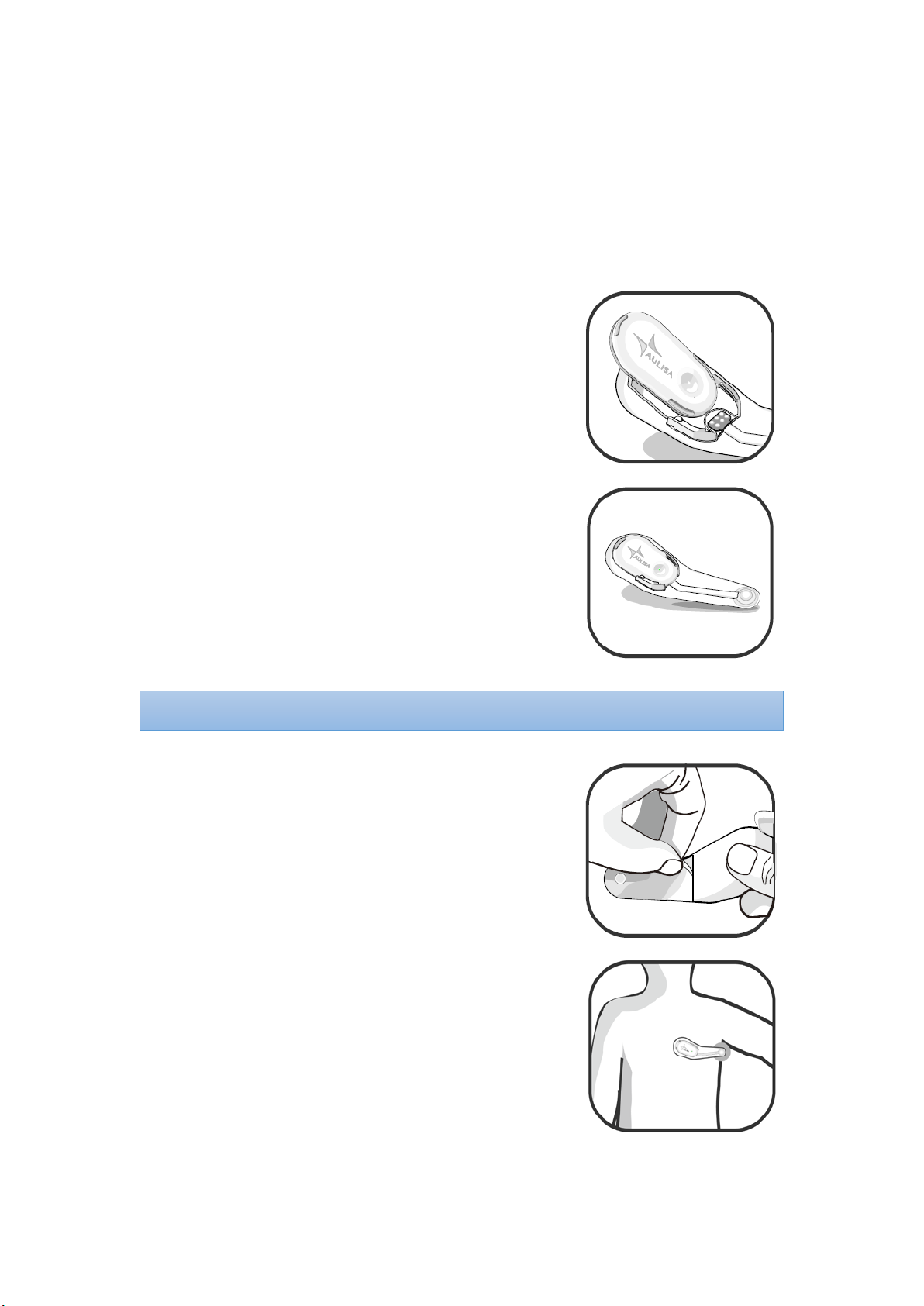
Device Overview
Device Components
Thermometer Box Sensor Patch
Device Description
The Thermometer Module is composed of Thermometer Box and Sensor Patch. It
must be used within 32.8 feet (10 meters) to the Display Unit (for GA1000 Series), or
to the Receiver/Transponder (for GA2000 Series).
Thermometer Box
The reusable, compact-sized, battery-operated Thermometer Box is embedded with
a Bluetooth module. The battery is changeable.

8
Sensor Patch
The medical grade and disposable Sensor Patch which is equipped with a
Thermometer Box holder and a Sensor probe can be used up to 24 hours, while some
users may want to change adhesives more often depending on skin type and
comfortability. Additional Sensor Patch can be purchased separately as needed.
Device Intended Use
The Thermometer Module is indicated for continuous armpit body temperature
monitoring for adult, pediatric, and infant patients. The intended environments of
use are hospitals, medical facilities, home care, and subacute environments.
Device Principle of Operation
The Thermometer Module applies the digital temperature sensor to detect
temperature and convert to a digital read-out.
9
Device Setting Up
Before you begin your monitoring session, unpack the Thermometer Module and
become familiar with its parts.
Step 1:
Make sure the connector of the Thermometer
Box aligns with the connector on the holder.
Step 2:
Secure the Thermometer Box onto the holder of
the Sensor Patch.
Step 3:
Peel the releasing paper off the Sensor Patch.
Step 4:
Attach the sensor probe to the center of the
armpit, with the Thermometer Box placed on
the chest.
NOTE:
The Power LED will blink green when the power is ON.

10
Step 5:
Let the arm drop naturally at the side to cover
the sensor
probe for 12 minutes before attempting a
reading.
Step 6:
Set up the GA1000 Series or GA2000 Series.
Step 7:
Wait for the wireless connection of the system to be established. Once
connected, the vital signs and the Thermometer Module status information
will appear on the MAIN screen.
NOTE: Refer to the GA1000 Series Instructions for Use (7MN00021-01) or GA2000 Series
Instructions for Use (7MN00022-01) for setting up instructions and verifying system
operation.
NOTE: The Thermometer Module only measures axillary (armpit) temperature
NOTE: Refer to “Device Pairing” section below for more information.

11
Device Pairing
Automatic Pairing
GA1000 Series
The Display Unit automatically detects and connects to the Thermometer Module in
the same starter kit. Press the "PAIR" button on the MAIN screen to force the system
pairing when the connection is not established automatically.
GA2000 Series
The Receiver/Transponder automatically detects and connects to the Thermometer
Module in the same starter kit only when the connection between the Display Unit
and the Receiver/Transponder has been established first.
Manual Pairing
Follow the below instructions to manually setup pairing.
Step 1: Turn on the Display Unit.
Step 2: In the Setting menu, select “PAIRING”.(for GA1000 Series)
In the Setting menu, select “PAIRING”→“SENSOR MODULE”. (for GA2000
Series)
Step 3: Scan the QR Code or key in the serial number located on the back of the
Thermometer Box.
Step 4: Check if the serial number (SN) displayed matches with the one on the
Thermometer Box.
Step 5: Press “CONFIRM” on the Display Unit.
Step 6: Assemble the Thermometer Box and the Sensor Patch to power on the
device.
Step 7: To confirm that the process was successful, ensure that the Bluetooth
NOTE: The Thermometer Module must be placed within 32.8 feet (10 meters) to the
Display Unit (for GA1000 Series), or to the Receiver/Transponder (for GA2000 Series).
NOTE: The Bluetooth connection status icon will turn blue once the pairing succeeds.
NOTE: Up to two (2) Thermometer Modules can be stored on the Display Unit.
12
connection status icon on the MAIN screen of the Display Unit is lit blue.
Device Power Off
Detach the Thermometer Box from the Sensor Patch and the Power LED will go off.
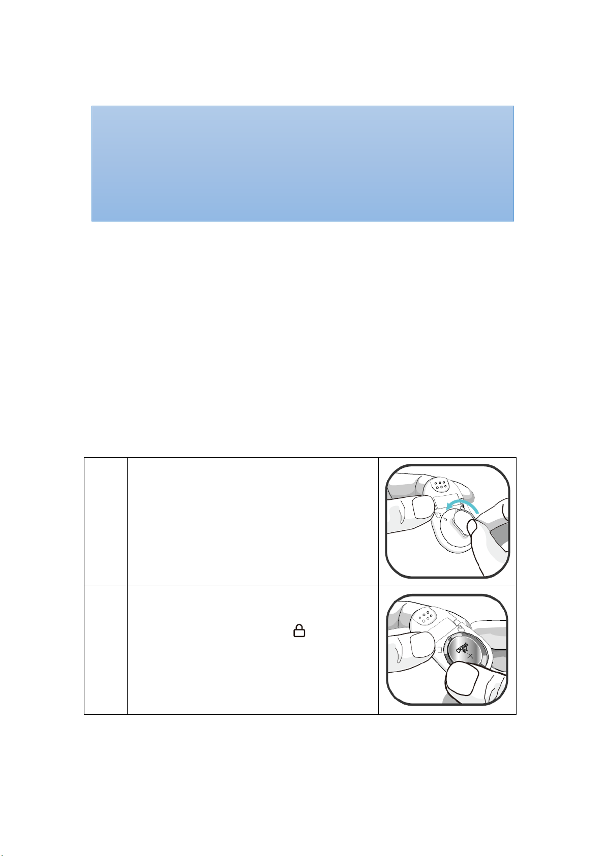
Device Battery Replacement
The Thermometer Module is powered by a button cell. When the low battery alarm
appears on the MAIN screen of the Display Unit, the battery is exhausted and needs
replacement. Follow the instructions below to replace the battery.
Step 1:
Take off the battery cover by using a coin,
turning the cover clockwise, and remove the
battery.
Step 2:
Insert a new CR2025 battery into the battery
chamber and replace the cover. Align the mark
on the cover with the lock icon .
NOTE: Make sure the battery is installed before use.
NOTE: The Thermometer Module remains paired with the system until the serial
number is deleted from the list.
NOTE: The Thermometer Module must be placed within 32.8 feet (10 meters) to the
Display Unit (for GA1000 Series), or to the Receiver/Transponder (for GA2000 Series).
NOTE: The Power LED blinks green when the power is ON.
13
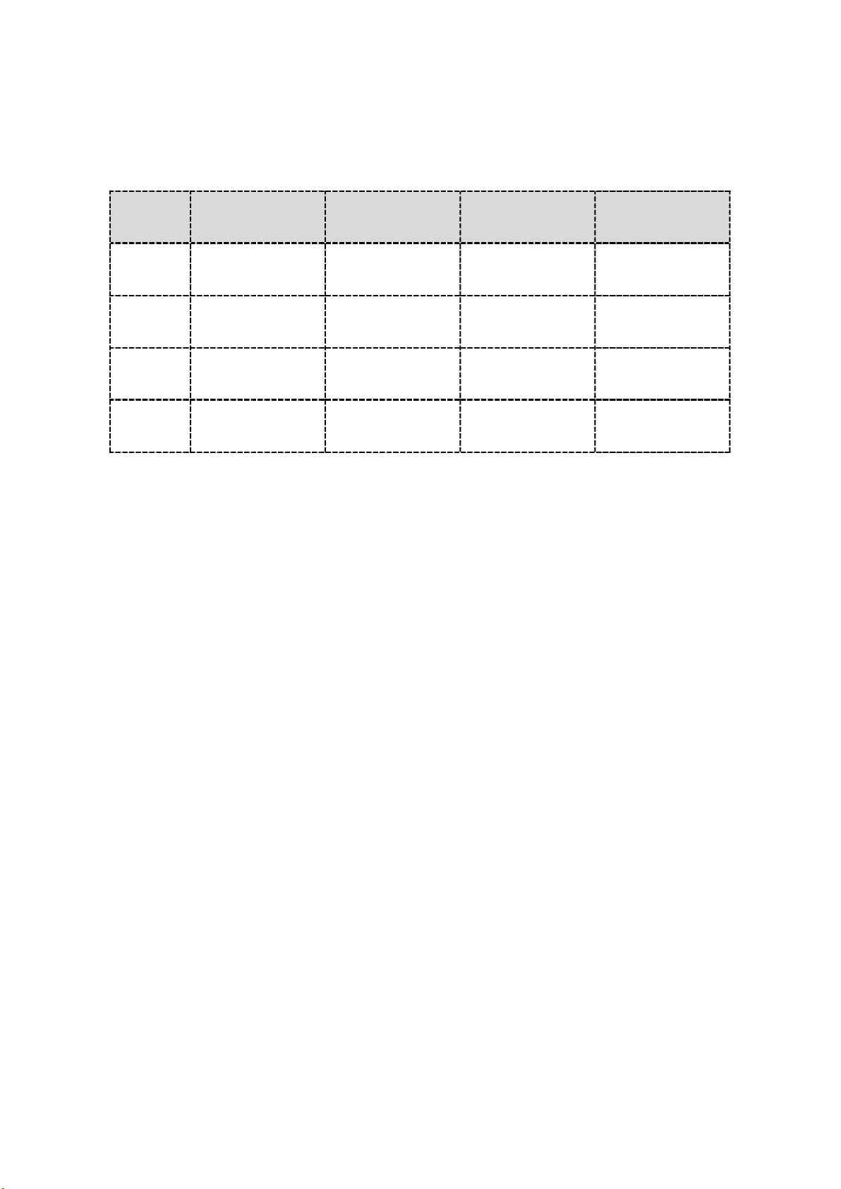
Normal Body Temperature Ranges
Type
Age Axillary (Armpit) Oral Ear Rectal
0-2y 94.5°F – 99.1°F
(34.7°C – 37.3°C) N/A 97.5°F – 100.4°F
(36.4°C – 38.0°C)
97.9°F – 100.4°F
(36.6°C – 38.0°C)
3-10y 96.6°F – 98.0°F
(35.9°C – 36.7°C)
95.9°F – 99.5°F
(35.5°C – 37.5°C)
97.5°F – 100.0°F
(36.4°C – 37.8°C)
97.9°F – 100.4°F
(36.6°C – 38.0°C)
11-65y 95.3°F – 98.4°F
(35.2°C – 36.9°C)
97.6°F – 99.6°F
(36.4°C – 37.6°C)
96.6°F – 99.7°F
(35.9°C – 37.6°C)
98.6°F – 100.6°F
(37.0°C – 38.1°C)
> 65y 96.0°F – 97.4°F
(35.6°C – 36.3°C)
96.4°F – 98.5°F
(35.8°C – 36.9°C)
96.4°F – 99.5°F
(35.8°C – 37.5°C)
97.1°F – 99.2°F
(36.2°C – 37.3°C)
Source: www.medguidance.com
Alarm
For more information about the alarm, refer to the GA1000 Series Instructions for
Use (7MN00021-01) or GA2000 Series Instructions for Use (7MN00022-01).
Care and Maintenance
The advanced digital circuitry within the Thermometer Module requires no
calibration or periodic maintenance. Field service or repair of this system is not
possible. Do not attempt to open the case other than the battery cover for that will
cause damage and void the warranty. If the Thermometer Module is not functioning
properly, see “Troubleshooting” section for more information.
Cleaning
Thermometer Box - it is reusable. Lightly wipe the surface of it with a soft cloth
dampened with rubbing alcohol before each use. Allow the device to dry thoroughly
before reuse.
Sensor Patch - it is for single use. No cleaning is needed.

14
CAUTION!!! Do not pour or spray any liquids onto this device, and do not allow any
liquids to enter any openings in the device.
CAUTION!!! Do not immerse the device in liquid and do not use caustic or abrasive
cleaning agents on the device.

15
Troubleshooting
Problem Possible Solution
Cannot power on the
Thermometer Module
1. Change a new battery.
2. Make sure the Thermometer Box is
assembled with the Sensor Patch firmly.
Unusual temperature data 1. Recheck device's location or contact with
the armpit.
2. Keep this device attached for twelve (12)
minutes before reading temperature.
3. Keep arm in natural dropping position
consistently.
4. Use this device under instructed operation
temperature.
5. Cover the sensor probe with arm.
Cannot establish
system connection
1. Make sure the Infant Thermometer Module
is within 32.8 feet (10 meters) spherical
radius to the Display Unit (for GA1000
Series), or to the Receiver/Transponder (for
GA2000 Series).
2. Power off the system and retry.
For additional troubleshooting, refer to the GA1000 Series Instructions for Use
(7MN00021-01) or GA2000 Series Instructions for Use (7MN00022-01).
If these solutions do not correct the problem, please contact your distributor, or
contact Aulisa by going online at www.aulisa.com under "Contact Us".
CAUTION!!! This system is a precision electronic instrument and must be repaired by
knowledgeable and specially trained Aulisa personnel only. Do not attempt to open the
case other than the battery cover or repair the electronics.

16
Manufacturer’s Declaration
Refer to the following table for specific information regarding compliance to IEC
60601-1-2 for this device.
Guidance and manufacturer's declaration – electromagnetic emissions - for all
EQUIPMENT and SYSTEMS

17
Guidance and manufacturer's declaration – electromagnetic immunity - for all
EQUIPMENT and SYSTEMS

18
Guidance and manufacturer's declaration – electromagnetic immunity - for
EQUIPMENT and SYSTEMS that are not LIFE-SUPPORTING

19
FCC Compliance
Declaration of Conformity with FCC for Electromagnetic Compatibility
This device complies with Part 15 of the FCC Rules. Operation is subject to the
following two conditions: (1) this device may not cause harmful interference, and (2)
this device must accept any interference received, including interference that may
cause undesignated operation.
Federal Communications Commission (FCC) Notice
This equipment has been tested and found to comply with the limits for a Class B
digital device, pursuant to part 15 of the FCC Rules. These limits are designed to
provide reasonable protection against harmful interference in a residential
installation. This equipment generates, uses, and can radiate radio frequency energy.
If not installed and used in accordance with the instructions, it may cause harmful
interference to radio or television reception, which can be determined by turning the
equipment off and on. The user is encouraged to try to correct the interference by
one or more of the following measures:
(1) Reorient or relocate the receiving antenna.
(2) Increase the separation between the equipment and receiver.
(3) Connect the equipment into an outlet on a circuit different from that to which the
receiver is connected.
(4) Consult the dealer or an experienced radio/TV technician for help.
The device is designed and manufactured not to exceed the emission limits for
exposure to radio frequency (RF) energy set by the Federal Communications
Commission of the U.S. Government. These limits are part of comprehensive
guidelines and establish permitted levels of RF energy for the general population.
The guidelines are based on the safety standards previously set by both U.S. and
international standards bodies. This equipment has been shown to be capable of
compliance for localized specific absorption rate (SAR) for uncontrolled environment/
general population exposure limits specified in ANSI/IEEE Std. C95.1-1992 and has
been tested in accordance with the measurement procedures specified in IEEE Std.
1528-200X (Draft 6.5, January 2002).
FCC Radiation Exposure Statement
For body worn operation, to maintain compliance with FCC RF exposure guidelines,
use only accessories that contain nonmetallic components. RF exposure separation
distance is 5 mm. Use of other accessories may violate FCC RF exposure guidelines
Other manuals for Guardian Angel Rx
1
This manual suits for next models
4
Table of contents
Other Aulisa Control Unit manuals


