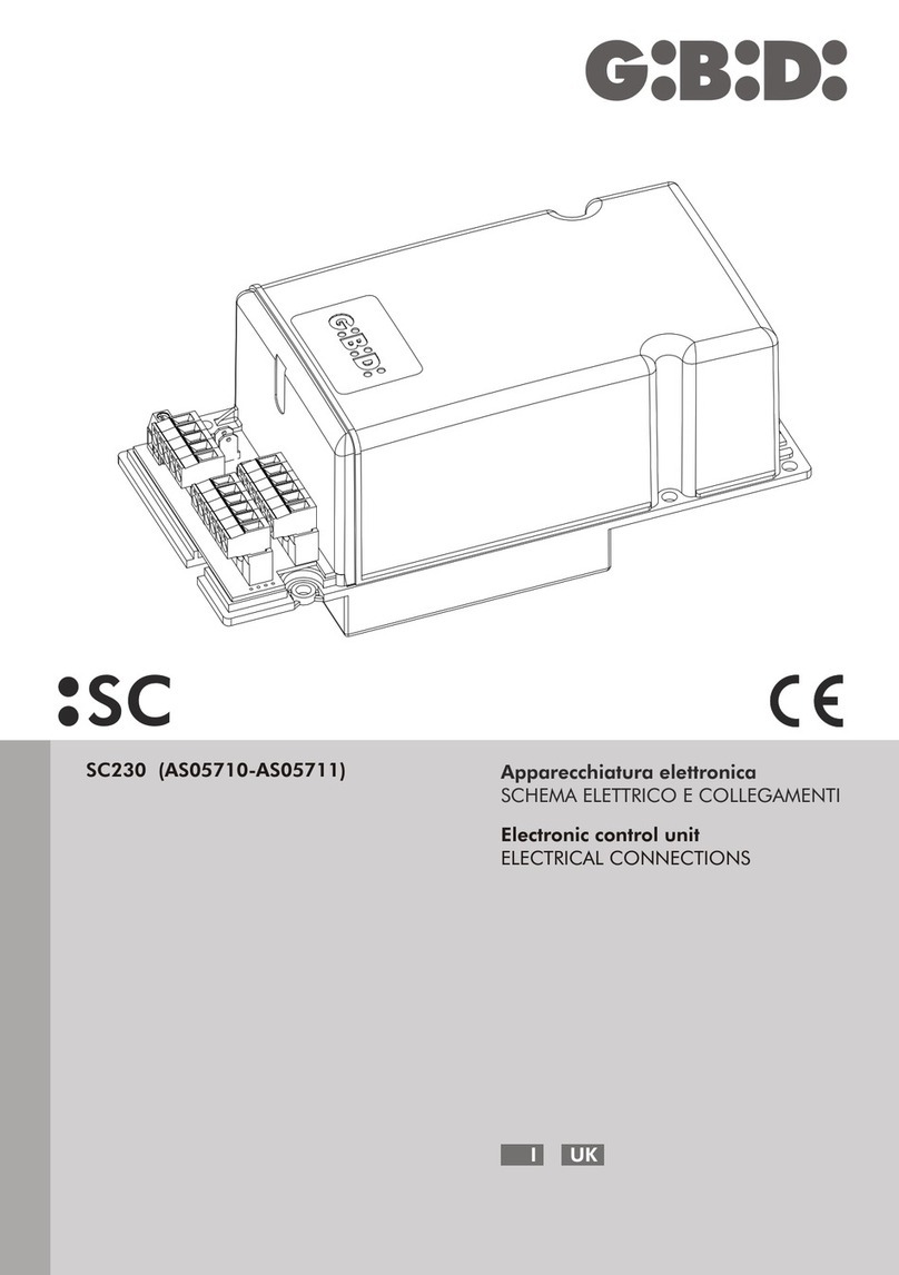
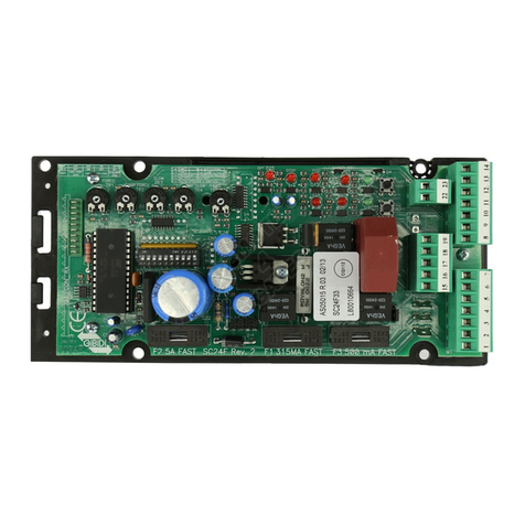
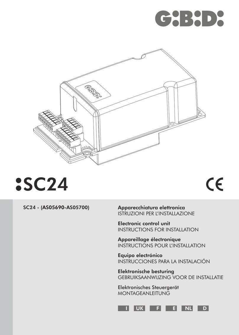
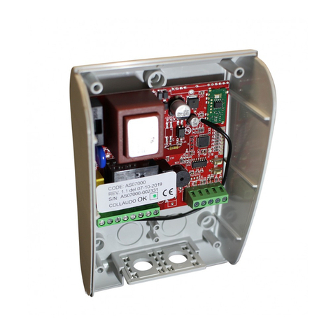
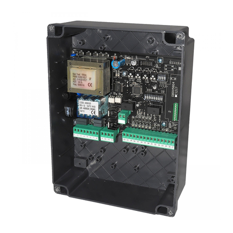
GiBiDi SC230 User manual

Sede Legale
Sede Amministrativa
Ufficio Commerciale
Stabilimento:
46025 Poggio Rusco (Mantova) ITALY
Via Abetone Brennero, 177/B
Tel. 0039 0386 522011 r.a.
Fax Ufficio Commerciale 0039 0386 522031
ISO 9001 - Cert.n°0079
www.gibidi.comwww.gibidi.com
AIC7080 - 04/07 -REV01 GRAPHIC CENTER
AUTOMATISMI PROFESSIONALI PER CANCELLI E GARAGES - PROFESSIONAL AUTOMATIC DEVICES FOR GATES AND GARAGE DOORS
SC230
APPARECCHIATURA ELETTRONICA - ISTRUZIONI PER L’INSTALLAZIONE
ELECTRONIC CONTROL UNIT - INSTRUCTIONS FOR INSTALLATIONS
APPAREIL ÉLECTRONIQUE - INSTRUCTIONS POUR LE MONTAGE
EQUIPO ELECTRÓNICO - INSTRUCCIONES PARA EL MONTAJE
ELEKTRONIKGERÄT - INSTRUCTIEHANDLEIDING
EQUIPAMENTO ELECTRÓNICO - INSTRUÇÕES DE INSTALAÇÃO
ELEKTRONISCHE APPARATUUR - INSTALLATIONSANLEITUNG
LEGGERE ATTENTAMENTE QUESTO MANUALE PRIMA DI PROCEDERE ALL’INSTALLAZIONE.
I
•Questo prodotto è stato collaudato in Gi.Bi.Di. verificando la perfetta corrispondenza delle caratteristiche alle direttive
vigenti.
•La Gi.Bi.Di. Continental S.p.A. si riserva la facoltà di modificare i dati tecnici senza avviso, in funzione dell’evoluzione del
prodotto.
UK
•This product has been tested in Gi.Bi.Di. verifying the perfect correspondence of the characteristics to the cur rent
directive.
•Gi.Bi.Di. Continental S.p.A. reserves the right to modify the technical data without prior notice depending on the product
development.
PLEASE READ CAREFULLY THIS MANUAL BEFORE PROCEEDING WITH THE INSTALLATION.
F
•Ce produit a été essayé en Gi.Bi.Di. en vérifiant la correspondance parfaite des caractéristiques aux règles en vigueur.
•Gi.Bi.Di. Continental S.p.A. se réserve la faculté de modifier les données techniques sans aucun préavis suivant
l’évolution de ses produits.
S’IL VOUS PLAÎT DE LIRE AVEC ATTENTION CETTE MANUAL AVANT DE PROCÉDER AVEC L’INSTALATION.
E
•Este producto ha sido probado en Gi.Bi.Di. averiguando la perfecta correspondencia de las características a las normas
vigentes.
•La empresa Gi.Bi.Di. Continental S.p.A. se reserva el derecho de modificar los datos técnicos sin previo aviso, en
función de la evolución del producto.
POR FAVOR LEER CON ATENCIÓN ESTE MANUAL ANTES DE PROCEDER CON LA INSTALACIÓN.
D
•Dieses Produkt wurde in Gi.Bi.Di. geprüft um die perfekte Entsprechung der merkmäle an die geltende vorschrif ten zu
prüfen.
•Gi.Bi.Di. Continental S.p.A. behält sich das recht vor, die technischen daten der produktentwicklung entsprechend ohne
voranzeige abzuändern.
BITTE LESEN SIE VORSICHTIG DIESEN MANUAL BEVOR MIT DER ANGLAGE VORZUGEHEN.
P
•Este produto foi testado em Gi.Bi.Di. verificando a correspondência perfeita das características ao normas vigentes.
•A Gi.Bi.Di. Continental S.p.A. reserva-se o direito de modificar os dados técnicos sem pré-aviso em função de evolução
do produto.
LER COM ATENÇÃO ESTE MANUAL ANTES DE PROCEDER COM A INSTALAÇÃO.
NL
•Dit product werd gekeurd in Gi.Bi.Di. Er werd nauwlettend gecontroleerd of de kenmerken van het product perfect
overeenkomen met de geldige richtlijnen.
•Gi.Bi.Di. Continental S.p.A. behoudt zich het recht voor de technische gegevens te wijzigen zonder waarschuwing vooraf,
als dat nodig is voor de evolutie van het product.
LEES DEZE GEBRUIKSAANWIJZING ZEER AANDACHTIG ALVORENS DE INSTALLATIE AAN TE VATTEN.

SC230
CARATTERISTICHE TECNICHE
•Led rossi di segnalazione dei contatti n.c. (photo, safety dev, fcc, fca, stop).
•Led verdi di segnalazione dei contatti n.a. (start e ped).
•Pulsanti START e PED a bordo scheda.
•Test sicurezze effettuato prima del movimento di apertura e chiusura.
•Rallentamento in apertura e chiusura comandato da 2 magneti supplementari da assemblare nella posizione
desiderata, ad una distanza relativa minima di almeno 500 mm. Il rallentamento è regolabile con opportuno trimmer
(SLOW).
•Arresto ed inversione del moto per 2 s dopo l'intervento dei dispositivi di sicurezza. Al successivo impulso di Star t il
moto riparte nel senso di liberazione dell'ostacolo.
•Possibilità di lettura giri motore per la funzione antischiacciamento tramite apposito sensore, sia in funzionamento
normale che in modalità rallentata. L'intervento del sensore determina l'arresto e l'inversione del moto per 2 s. Al
successivo impulso di Start il moto ripar te nel senso di liberazione dell'ostacolo.
•Funzionamento pedonale con apertura fissa di 10 s. Sono sempre abilitate la funzione condominiale e la richiusura
automatica.
•ALIMENTAZIONE DISPOSITIVI DI SICUREZZA. Il collegamento a questa alimentazione permetterà il TEST dei
dispositivi prima del moto. A questo morsetto vanno collegati i dispositivi di sicurezza che verranno alimentati solo
durante il ciclo di funzionamento.
CARATTERISTICHE TECNICHE / FUNZIONI
SC230
I
SC2302
Apparecchiatura SC230
Tipo
Apparecchiatura elettronica per l’automazione di un cancello
scorrevole con motore a 230Vac
Alimentazione 230Vac monofase 50/60 Hz
N° motori 1
Alimentazione motore 230Vac
Lampeggiante 230Vac 40W max.
Lampada spia 24Vac 3W max
Alimentazione accessori 24Vac 8W max comprensivi di alimentazione dispositivi di
sicurezza
Alimentazione dispositivi di sicurezza 24Vac 8W max comprensivi di alimentazione accessori
Ricevitore radio Ad innesto
Temperatura di utilizzo -20°C +60°C
Tempo di lavoro 240 s fisso
Tempo di pausa Regolabile da 2 a 215 s
Fig.1Fig.1
RXRX
F3F3
20 2120 21
GIBIDIGIBIDI
M5M5
SW1SW1
1010
500mA500mA
MOTMOT
PED (NO)PED (NO)
PHOTO (NC)PHOTO (NC)
START (NO)START (NO)
COMMONCOMMON
ONON
GNDGND
ANTANT
STOP (NC)STOP (NC)
SAFETY (NC)SAFETY (NC)
24Vac24Vac
AMP.
SLOW
AMP.
SLOW
STARTSTART
PEDPED
F1F1
SLOWSLOW
PAUSEPAUSE
AMP.AMP.
FORCEFORCE
JP1JP1
L1L1
230Vac 40W MAX230Vac 40W MAX
MOTOR 230VacMOTOR 230Vac
500mA500mA
FORCEFORCE
SC230SC230
11
22
3344
5566
7788
99
TR1TR1
TR2TR2
TR4TR4
TR3TR3
TR5TR5
DL8DL8 DL7DL7 DL6DL6 DL5DL5 DL4DL4 DL3DL3 DL2DL2 DL1DL1
3 4 5 6 73 4 5 6 7
CN6CN6
PEDPED
M3M3
STARTSTART
PHOTOPHOTO
SAFETY DEVSAFETY DEV
STOPSTOP
COMCOM
MOTOR
OPEN
MOTOR
OPEN
LAMPLAMP
MOTOR
CLOSE
MOTOR
CLOSE
M2M2
LAMPLAMP
MOTOR
COM
MOTOR
COM
PHASEPHASE
NEUTRALNEUTRAL
GNDGND
M4M4
24Vac24Vac
SECSEC
SPIASPIA
12V12V
IMPIMP
3,15A3,15A
F2F2
K3K3
K2K2 K6K6
K5K5
K1K1
K4K4
GNDGND
M4M4
24Vac24Vac
SECSEC
SPIASPIA
12V12V
IMPIMP
24Vac24Vac
24Vac 3W MAX24Vac 3W MAX
CN4CN4
CN5CN5
CN2CN2
CN3CN3
GNDGND
EARTHEARTH EXTERNALEXTERNAL
M1M1
T1T1
U5U5
1 21 2
8 9 10 11 12 138 9 10 11 12 13
14 15 16 17 18 1914 15 16 17 18 19
14 15 16 17 18 1914 15 16 17 18 19
12Vcc12Vcc
112233
INDUCTIVE SENSORINDUCTIVE SENSOR

In caso di guasto o anomalie di funzionamento staccare l’alimentazione a monte dell’apparecchiaura e chiamare
l’assistenza tecnica.
Verificare periodicamente il funzionamento delle sicurezze. Le eventuali riparazioni devono essere eseguite da
personale specializzato usando materiali originali e certificati.
AVVERTENZE PER L’UTENTE
•Prima di procedere con l’installazione bisogna predisporre a monte dell’impianto un interruttore magneto
termico o differenziale con portata massima 10A. L’interruttore deve garantire una separazione omnipolare dei
contatti, con distanza di apertura di almeno 3 mm.
•Per evitare possibili interferenze, differenziare e tenere sempre separati i cavi di potenza (sezione minima
1,5mm²) dai cavi di segnale (sezione minima 0,5mm²).
•Eseguire i collegamenti facendo riferimento alle tabelle seguenti e alla serigrafia allegata. Fare molta attenzione
a collegare in serie tutti i dispositivi che vanno collegati allo stesso ingresso N.C. (normalmente chiuso) e in
parallelo tutti i dispositivi che condividono lo stesso ingresso N.A. (normalmente aperto). Una errata
installazione o un uso errato del prodotto può compromettere la sicurezza dell’impianto.
•Tutti i materiali presenti nell’imballo non devono essere lasciati alla portata dei bambini in quanto potenziali
fonti di pericolo.
•Il costruttore declina ogni responsabilità ai fini del corretto funzionamento dell'automazione nel caso non
vengano utilizzati i componenti e gli accessori di propria produzione e idonei per l'applicazione prevista.
•Al termine dell’istallazione verificare sempre con attenzione il corretto funzionamento dell’impianto e dei
dispositivi utilizzati.
•Questo manuale d’istruzioni si rivolge a persone abilitate all’installazione di “apparecchi sotto tensione”
pertanto si richiede una buona conoscenza della tecnica, esercitata come professione e nel rispetto delle norme
vigenti.
•La manutenzione deve essere eseguita da personale qualificato.
•Prima di eseguire qualsiasi operazione di pulizia o di manutenzione scollegare l’apparecchiatura dalle rete di
alimentazione elettrica.
•L’apparecchiatura qui descritta deve essere utilizzata solo all’uso per il quale è stata concepita: la
motorizzazione di un cancello scorrevole a 230Vac, con motore Gi.Bi.Di..
•L’ utilizzo dei prodotti e la loro destinazione ad usi diversi da quelli previsti non è stata sperimentata dal
costruttore, pertanto i lavori eseguiti sono sotto la completa responsabilità dell’installatore.
•Segnalare l’automazione con targhe di avvertenza che devono essere visibili.
•Avvisare l’utente che bambini o animali non devono giocare o sostare nei pressi del cancello.
•Proteggere adeguatamente i punti di pericolo (per esempio mediante l’uso di una costa sensibile).
AVVERTENZE PER L’INSTALLAZIONE
I
LA FUNZIONE ANTI-SCHIACCIAMENTO NON ELIMINA L’OBBLIGO DI INSTALLARE I
DISPOSITIVI DI SICUREZZA PREVISTI DALLE NORMATIVE VIGENTI.
SC230 3

PROGRAMMAZIONE FUNZIONI (DIP SWITCH-Sw1)
I
I
SC2304 SC230 5
COLLEGAMENTI ELETTRICI: FASTON
COLLEGAMENTI ELETTRICI: MORSETTIERE
Le impostazioni vengono memorizzate durante la fase di riposo (cancello chiuso).
FUSIBILI DI PROTEZIONE
Posizione Segnale Descrizione
1 CN2 CN3 Collegamento terra
2 CN4 CN5 Collegamento condensatore motore
DIP Stato Funzione Descrizione
DIP 1
DIP 2
OFF
OFF PASSO – PASSO CON STOP
I impulso di Start :APRE
II impulso di Start :ARRESTA (non richiuderà in automatico)
III impulso di Start :CHIUDE
IV impulso di Start :APRE
DIP 1
DIP 2
ON
OFF PASSO - PASSO
I impulso di Start :APRE
II impulso di Start :CHIUDE
III impulso di Start :APRE
DIP 1
DIP 2
OFF
ON CONDOMINIALE
In apertura non riceve altri comandi di Star t dopo il primo, in pausa successivi comandi di
Start ricaricano il tempo di pausa
I impulso di Start :APRE
Successivi impulsi di Start :Ininfluenti
Pausa da FCA
Impulso di Start durante la pausa :Ricarica il tempo pausa (se dip 6 ON)
Oppure CHIUDE (se dip 6 OFF)
Successivo impulso di Start :APRE
DIP 1
DIP 2
ON
ON UOMO PRESENTE Se mantenuto premuto pulsante Start :APRE
Se mantenuto premuto pulsante Pedonale :CHIUDE
DIP 3 ON Abilita il prelampeggio di 2 s prima dell’attivazione del motore in apertura e chiusura
DIP3 OFF PRELAMPEGGIO Disabilita il prelampeggio
DIP 4 ON
Abilita il TEST dei dispositivi di sicurezza prima di attivare il ciclo di aper tura e chiusura.
Solo se i dispositivi saranno per fettamente funzionanti il ciclo potrà iniziare, in caso
contrario tre lampeggi prolungati indicheranno l’anomalia.
DIP 4 OFF
TEST SICUREZZE
Disabilita il test dei dispositivi di sicurezza.
DIP 5 ON
Quando viene intercettata la fotocellula, sia in apertura che in chiusura, viene bloccato il
moto del cancello fintanto che la fotocellula stessa non viene liberata. Successivamente si
ha sempre una fase di apertura.
DIP 5 OFF
FOTOCELLULA IN APERTURA
Disabilita la funzione fotocellula in apertura.
DIP 6 ON Abilita la chiusura automatica dopo il tempo di pausa regolabile tramite il trimmer TR1
PAUSE da 2 a 215 s.
DIP 6 OFF
RICHIUSURA AUTOMATICA
Disabilita la chiusura automatica.
DIP 7 ON
Abilita il rallentamento sia in aper tura che in chiusura quando viene intercettato il rispettivo
fine corsa. La velocità di rallentamento è regolata dal trimmer TR3 SLOW. Questa funzione
prevede l’impiego di 4 magneti (vedere disegno 2)
DIP 7 OFF
RALLENTAMENTO
Disabilita la funzione rallentamento. Necessaria la presenza di 2soli magneti (vedere
disegno 2)
DIP 8 ON Riduce il tempo di pausa a 3 s dopo l’intervento delle fotocellule.
DIP 8 OFF RICHIUSURA RAPIDA Disabilita la funzione di richiusura rapida
DIP 9 ON
Abilita il funzionamento del sensore giri motore. In seguito ad una riduzione del numero di
giri del motore (ad es. ostacolo) il sensore inter viene bloccando il moto ed inver tendone la
direzione per 2 s al fine di liberare l’ostacolo. Al successivo impulso di Start il moto ripar te
nel senso di liberazione dell’ostacolo
DIP 9 OFF
SENSORE GIRI MOTORE
Disabilita il sensore giri motore
DIP 10 ON Disabilita l’ingresso STOP
DIP 10 OFF
ESCLUSIONE PULSANTE STOP
Ingresso STOP abilitato
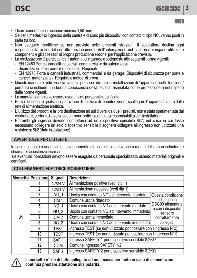
Morsetto Posizione Segnale Descrizione
1 PHASE Alimentazione 230 Vac
M1 2 NEUTR Alimentazione 230 Vac
3 LAMP
Uscita lampeggiatore 230Vac 40W
4 LAMP Uscita lampeggiatore 230Vac 40W
Lampeggio lento in apertura, spento in pausa
lampeggio veloce in chiusura.
5 COM Comune motore
6 OPEN Collegamento motore (apertura)
M2
7 CLOSE Collegamento motore (chiusura)
8 PED
Ingresso PEDONALE (N.A.)
9 START Ingresso START (N.A.)
10 PHOTO Ingresso FOTOCELLULA (N.C.). Se non utilizzato ponticellare con morsetto n°13
11 SAFETY Ingresso DISPOSITIVI DI SICUREZZA (N.C.). Se non utilizzato ponticellare con morsetto n°13
12 STOP Ingresso STOP (N.C.).Se non utilizzato ponticellare con morsetto n°13oppure porre dip 10 in ON
M3
13 COM COMUNE INGRESSI-USCITE
14 GND
Alimentazione accessori esterni e massa sensore induttivo (cavo blu)
15 24Vac Alimentazione 24Vac accessori esterni (fotocellule, radio, etc)
16 SEC Alimentazione 24Vac dispositivi di sicurezza esterni presente solo durante il ciclo di funzion amento
17 SPIA Uscita SPIA 24Vac 3W max Lampeggio lento in apertura, accesa fissa in pausa ,
lampeggio veloce in chiusura.
18 12V Alimentazione positiva sensore induttivo (cavo marrone)
M4
19 IMP Ingresso sensore induttivo (cavo nero)
20 GND
Ingresso CALZA ANTENNA
M5 21 ANT Ingresso SEGNALE ANTENNA
Posizione Valore Tipo Descrizione
F1 500 mA RAPIDO Protegge le uscite di alimentazione ACCESSORI e DISPOSITIVI di SICUREZZA
F2 RAPIDO Protegge l’apparecchiatura all’ingresso alimentazione 230 Vac
F3 500 mA RAPIDO Protegge l’uscita del lampeggiatore
3,15A

PROGRAMMAZIONE FUNZIONI (DIP SWITCH-Sw1)
I
I
SC2304 SC230 5
COLLEGAMENTI ELETTRICI: FASTON
COLLEGAMENTI ELETTRICI: MORSETTIERE
Le impostazioni vengono memorizzate durante la fase di riposo (cancello chiuso).
FUSIBILI DI PROTEZIONE
Posizione Segnale Descrizione
1 CN2 CN3 Collegamento terra
2 CN4 CN5 Collegamento condensatore motore
DIP Stato Funzione Descrizione
DIP 1
DIP 2
OFF
OFF PASSO – PASSO CON STOP
I impulso di Start :APRE
II impulso di Start :ARRESTA (non richiuderà in automatico)
III impulso di Start :CHIUDE
IV impulso di Start :APRE
DIP 1
DIP 2
ON
OFF PASSO - PASSO
I impulso di Start :APRE
II impulso di Start :CHIUDE
III impulso di Start :APRE
DIP 1
DIP 2
OFF
ON CONDOMINIALE
In apertura non riceve altri comandi di Star t dopo il primo, in pausa successivi coman di di
Start ricaricano il tempo di pausa
I impulso di Start :APRE
Successivi impulsi di Start :Ininfluenti
Pausa da FCA
Impulso di Start durante la pausa :Ricarica il tempo pausa (se dip 6 ON)
Oppure CHIUDE (se dip 6 OFF)
Successivo impulso di Start :APRE
DIP 1
DIP 2
ON
ON UOMO PRESENTE Se mantenuto premuto pulsante Start :APRE
Se mantenuto premuto pulsante Pedonale :CHIUDE
DIP 3 ON Abilita il prelampeggio di 2 s prima dell’attivazione del motore in apertura e chiusura
DIP3 OFF PRELAMPEGGIO Disabilita il prelampeggio
DIP 4 ON
Abilita il TEST dei dispositivi di sicurezza prima di attivare il ciclo di aper tura e chiusura.
Solo se i dispositivi saranno per fettamente funzionanti il ciclo potrà iniziare, in caso
contrario tre lampeggi prolungati indicheranno l’anomalia.
DIP 4 OFF
TEST SICUREZZE
Disabilita il test dei dispositivi di sicurezza.
DIP 5 ON
Quando viene intercettata la fotocellula, sia in apertura che in chiusura, viene bloccato il
moto del cancello fintanto che la fotocellula stessa non viene liberata. Successivamente si
ha sempre una fase di apertura.
DIP 5 OFF
FOTOCELLULA IN APERTURA
Disabilita la funzione fotocellula in apertura.
DIP 6 ON Abilita la chiusura automatica dopo il tempo di pausa regolabile tramite il trimmer TR1
PAUSE da 2 a 215 s.
DIP 6 OFF
RICHIUSURA AUTOMATICA
Disabilita la chiusura automatica.
DIP 7 ON
Abilita il rallentamento sia in aper tura che in chiusura quando viene intercettato il rispettivo
fine corsa. La velocità di rallentamento è regolata dal trimmer TR3 SLOW. Questa funzione
prevede l’impiego di 4 magneti (vedere disegno 2)
DIP 7 OFF
RALLENTAMENTO
Disabilita la funzione rallentamento. Necessaria la presenza di 2soli magneti (vedere
disegno 2)
DIP 8 ON Riduce il tempo di pausa a 3 s dopo l’intervento delle fotocellule.
DIP 8 OFF RICHIUSURA RAPIDA Disabilita la funzione di richiusura rapida
DIP 9 ON
Abilita il funzionamento del sensore giri motore. In seguito ad una riduzione del numero di
giri del motore (ad es. ostacolo) il sensore inter viene bloccando il moto ed inver tendone la
direzione per 2 s al fine di liberare l’ostacolo. Al successivo impulso di Start il moto ripar te
nel senso di liberazione dell’ostacolo
DIP 9 OFF
SENSORE GIRI MOTORE
Disabilita il sensore giri motore
DIP 10 ON Disabilita l’ingresso STOP
DIP 10 OFF
ESCLUSIONE PULSANTE STOP
Ingresso STOP abilitato
Morsetto Posizione Segnale Descrizione
1 PHASE Alimentazione 230 Vac
M1 2 NEUTR Alimentazione 230 Vac
3 LAMP
Uscita lampeggiatore 230Vac 40W
4 LAMP Uscita lampeggiatore 230Vac 40W
Lampeggio lento in apertura, spento in pausa
lampeggio veloce in chiusura.
5 COM Comune motore
6 OPEN Collegamento motore (apertura)
M2
7 CLOSE Collegamento motore (chiusura)
8 PED
Ingresso PEDONALE (N.A.)
9 START Ingresso START (N.A.)
10 PHOTO Ingresso FOTOCELLULA (N.C.). Se non utilizzato ponticellare con morsetto n°13
11 SAFETY Ingresso DISPOSITIVI DI SICUREZZA (N.C.). Se non utilizzato ponticellare con morsetto n°13
12 STOP Ingresso STOP (N.C.).Se non utilizzato ponticellare con morsetto n°13oppure porre dip 10 in ON
M3
13 COM COMUNE INGRESSI-USCITE
14 GND
Alimentazione accessori esterni e massa sensore induttivo (cavo blu)
15 24Vac Alimentazione 24Vac accessori esterni (fotocellule, radio, etc)
16 SEC Alimentazione 24Vac dispositivi di sicurezza esterni presente solo durante il ciclo di funzion amento
17 SPIA Uscita SPIA 24Vac 3W max Lampeggio lento in apertura, accesa fissa in pausa ,
lampeggio veloce in chiusura.
18 12V Alimentazione positiva sensore induttivo (cavo marrone)
M4
19 IMP Ingresso sensore induttivo (cavo nero)
20 GND
Ingresso CALZA ANTENNA
M5 21 ANT Ingresso SEGNALE ANTENNA
Posizione Valore Tipo Descrizione
F1 500 mA RAPIDO Protegge le uscite di alimentazione ACCESSORI e DISPOSITIVI di SICUREZZA
F2 RAPIDO Protegge l’apparecchiatura all’ingresso alimentazione 230 Vac
F3 500 mA RAPIDO Protegge l’uscita del lampeggiatore
3,15A

VERIFICHE FINALI E COLLAUDO
!DIP 1 E DIP 2 entrambi OFF: Passo passo con stop
!DIP 3 OFF: Prelampeggio escluso
!DIP 4 OFF: Test dispositivi di sicurezza escluso
!DIP 5 OFF: Fotocellula in apertura esclusa
!DIP 6 OFF: Chiusura automatica disabilitata
!DIP 7 OFF: Rallentamenti esclusi
!DIP 8 OFF: Richiusura rapida esclusa
!DIP 9 OFF: Sensore giri motore disabilitato
!DIP 10 OFF: Ingresso STOP abilitato
IMPOSTAZIONI DI DEFAULT
REGOLAZIONE TRIMMER
!I trimmer TR2, TR3, TR4, TR5 possono essere regolati anche durante il movimento del cancello,
verificando così immediatamente l'effetto.
!Il trimmer TR1 viene memorizzato solo durante la fase di riposo (cancello chiuso).
•TRIMMER TR1 regolato al minimo
•TRIMMER TR2, TR3 regolato al livello intermedio
•TRIMMER TR4, TR5 regolati al massimo
I
I
SC2306 SC230 7
FC chiusura
Fermo motore
FC rallentamento
in chiusura
FC rallentamento
in apertura
FC apertura
Fermo motore
500 600mm Fig.2Fig.2
Prima di dare tensione all'apparecchiatura occorre procedere alle seguenti verifiche:
1 Verificare l'impostazione corretta dei dip, secondo le esigenze.
2 Regolare il trimmer TR1 (PAUSE) impostando quindi il tempo di pausa desiderato (al max in senso
orario si ottengono 215 s)
3 Verificare i collegamenti elettrici: un collegamento errato può risultare dannoso sia per l'apparecchiatura
che per l'operatore.
4 Verificare la corretta posizione dei finecorsa (Fig.2). Fare attenzione alla corretta disposizione dei
magneti.
ALIMENTARE IL DISPOSITIVO
N.B.:Tra i relè K5 e K6 è presente un ponticello denominato JP1 che serve all'installatore per alimentare i
dispositivi di sicurezza (posizione 1-2) anche con cancello a riposo (normalmente l'alimentazione dei dispositivi
di sicurezza si ha solo durante il ciclo di apertura-pausa-chiusura) e fare i relativi controlli.
Ricordarsi di posizionare il ponticello nella posizione 2-3 prima di attivare il normale funzionamento, altrimenti
con l'uso del TEST SICUREZZE verrà segnalato un'anomalia e il cancello resterà bloccato (DIP4).
5 Verificare che i led rossi dei contatti normalmente chiusi siano accesi ed i led verdi dei contatti
normalmente aperti siano spenti
6 Verificare che facendo intervenire i fine corsa utilizzati si spengano i led corrispondenti.
7 Verificare che passando attraversando il raggio delle fotocellule il led corrispondente si spenga.
8 Verificare che facendo intervenire i dispositivi di sicurezza il led corrispondente si spenga.
9 Verificare che il motore sia bloccato e pronto per il funzionamento in posizione di CANCELLO A META'
CORSA. Rimuovere eventuali ostacoli nel raggio d'azione del cancello quindi dare un comando di START.
Al primo comando l'apparecchiatura comincia una fase di apertura, quindi verificare che la direzione del
moto del cancello sia corretta. In caso contrario invertire i fili nei morsetti OPEN CLOSE. Alla prima
manovra il cancello si fermerà sul primo fine corsa di apertura che incontra. Completare la manovra di
chiusura per consentire all'apparecchiatura di leggere tutti i fine corsa presenti ed allineare il cancello.
10 Ruotare il trimmer TR2 (FORCE) fino a trovare il valore forza/velocità desiderato (Fig.1).
11 Se attivata la funzione rallentamento ruotare il trimmer TR3 (SLOW) fino a trovare il valore di
rallentamento desiderato. (Fig.1).
12 Se attivato il sensore giri motore, ruotare il trimmer TR4 in senso antiorario fino a trovare il corretto
valore di intervento del sensore durante il moto a forza piena.
13 Se attivato il sensore giri motore e la funzione rallentamento ruotare il trimmer TR5 in senso antiorario
fino a trovare il corretto valore di intervento del sensore durante il moto rallentato.
Nota
In caso di disturbi elettrici o elettromagnetici ambientali, il cancello potrebbe fermarsi sul fine corsa previsto per
il rallentamento, al fine di impedire l'intervento dell'antischiacciamento contro il fermo meccanico. Per
ripristinare il corretto funzionamento effettuare una manovra completa di apertura e/o chiusura.
IMPOSTAZIONI DI DEFAULT
Trimmer Funzione Descrizione
TR1 PAUSE Regola il TEMPO di PAUSA da 2 a 215 s. Il valore aumenta ruotando in senso orario il trimmer.
TR2 FORCE Regola il livello della FORZA motore. La forza aumenta ruotando in senso orario il trimmer.
TR3 SLOW Regola il livello del RALLENTAMENTO. Ru otando in senso orario si ha una maggiore velocità/for za del cancello.
TR4 AMP.FORCE
Regola la sensibilità d’intervento del sensore giri motore durante il moto non rallentato. Ruotando il trimmer in senso
orario diminuisce la sensibilità.
TR5 AMP. SLOW
Regola la sensibilità d’intervento del sensore giri motore durante il moto rallentato. Ruotando il trimmer in senso orario
diminuisce la sensibilità.
ATTENZIONE: Con alcune motorizzazioni, in funzione delle
caratteristiche del cancello, potrebbe capitare che con
rallentamento massimo il motore vibri leggermente. In
questo caso regolare opportunamente il trimmer del
rallentamento evitando di posizionarlo al max.

Dichiarazione di conformità CE
Il fabbricante:
Gi.Bi.Di. Continental S.p.A.
Sede Legale
Sede Amministrativa-Ufficio Commerciale-Stabilimento :
Via Abetone Brennero, 177/B, 46025 Poggio Rusco (Mantova) ITALY
Tel. 0039 0386 522011 - Fax Uff.comm 0039 0386 522031
Dichiara che i prodotti:
Sono conformi alle seguenti Direttive CEE:
•Direttiva Bassa Tensione 73/23 e successive modifiche;
•Direttiva Compatibilità Elettromagnetica 89/336 e successive modifiche;
•Direttiva
e che sono state applicate le seguenti norme armonizzate:
Data 18/04/07 Firma Ammistratore Delegato
Oliviero Arosio
APPARECCHIATURA ELETTRONICA SC230
R&TTE 99/05
!EN60335-1, EN300 220-3, EN301 489-1, EN301 489-3
!EN61000-3-2, EN61000-3-3, EN61000-6-3, EN61000-6-1
SC2308
I
TECHNICAL SPECIFICATIONS
•Red warning LEDs of N.C. contacts (photocell, safety device, closing limit switch, opening limit switch, stop).
•Green warning LEDs of N.O. contacts (start and ped).
•Buttons START and PED on board.
•Safety test runs before the opening and closing movements.
•Deceleration during opening and closing controlled by 2 additional magnets to be assembled in the desired
position at a minimum relative distance of at least 500 mm. Deceleration is adjustable with a trimmer (SLOW).
•Stop and motion inversion for 2 seconds after intervention of the safety devices. At the next Star t pulse the motion
restarts in the obstacle freeing direction.
•Possibility of reading the motor rpm for the anti-crushing function by means of a sensor, both during normal
operation and in slow motion. The intervention of the sensor determines stopping and inversion of the motion for 2
seconds. At the next Start pulse the motion restar ts in the obstacle freeing direction.
•Pedestrian operation with fixed opening of 10 seconds. The automatic function and automatic closing are always
enabled.
•SAFETY DEVICE POWER SUPPLY. Connection to this power supply allows TESTING the devices before motion.
The safety devices must be connected to this terminal and will be powered only during the operating cycle.
FEATURES / FUNCTIONS
UK
SC230 9
Control unit SC230
Type Electronic control unit for automation of a sliding gate with 230
VAC motor
Power supply 230VAC, single-phase, 50/60 Hz
No. of motors 1
Motor power supply 230 VAC
Flashlight 230 VAC 40W max
Warning light 24 VAC 3W max
Accessory power supply 24 VAC 8W max including safety device power supply
Safety device power supply 24 VAC 8W max including accessory power supply
Radio-receiver Plug-in
Operating temperature -20°C +60°C
Working time 240 s fixed
Pause time Adjustable between 2 and 215 s

SC230
UK
SC230
UK
10
In the event of an operating fault or failure, cut the power upstream of the control unit and call Technical Service.
Periodically check functioning of the safety devices. Any repairs must be carried out by specialised personnel
using original and certified materials.
WARNINGS FOR THE USER
•Before proceeding with installation, fit a magnetothermal or differential switch with a maximum capacity of
10A upstream of the system. The switch must guarantee omnipolar separation of the contacts with an opening
distance of at least 3 mm.
•To prevent possible interference, differentiate the power cables and always keep them separate (minimum
cross-section 1.5 mm²) from the signal cables (minimum cross-section 0.5 mm²).
•Make the connections referring to the following tables and to the attached screen-print. Be extremely careful to
connect in series all the devices that are connected to the same N.C. (normally closed) input, and in parallel all
the devices that share the same N.O. (normally open) input. Incorrect installation or improper use of the product
may compromise system safety.
•Keep all the materials contained in the packaging away from children, since they pose a potential risk.
•The manufacturer declines all responsibility for improper functioning of the automated device if the original
components and accessories suitable for the specific application are not used.
•After installation, always carefully check proper functioning of the system and the devices used.
•This instruction manual addresses persons qualified for installation of “live equipment”. Therefore, good
technical knowledge and professional practice in compliance with the regulations in force are required.
•Maintenance must be carried out by qualified personnel.
•Before carrying out any cleaning or maintenance operation, disconnect the control unit from the mains.
•The control unit described here may only be used for the purpose for which it was designed: 230 VAC
motorization of a sliding gate with a Gi.Bi.Di. Motor.
•Use of the product for purposes different from the intended use has not been tested by the manufacturer,
therefore any work is carried out on full responsibility of the installer.
•Mark the automated device with visible warning plates.
•Warn the user that children or animals may not play or stand around near the gate.
•Appropriately protect the danger points (for example, using a sensitive frame).
INSTALLATION WARNINGS
THE ANTI-CRUSHING FUNCTION DOES NOT RELIEVE THE INSTALLER FROM THE OBLIGATION
TO INSTALL THE SAFETY DEVICES AS REQUIRED BY THE REGULATIONS IN FORCE.
ELECTRICAL CONNECTIONS: FASTONS
ELECTRICAL CONNECTIONS: TERMINAL BOARDS
PROTECTION FUSES
11
Position Signal Description
1 CN2 CN3 Ground connection
2 CN4 CN5 Motor capacitor connection
Terminal Position Signal Description
1 PHASE 230 VAC power supply
M1 2 NEUTR 230 VAC power supply
3 LAMP
Flashlight output 230 VAC 40W
4 LAMP Flashlight output 230 VAC 40W
Slow flashing in opening, turned off in pause, fast
flashing in closing.
5 COM Motor common
6 OPEN Motor connection (opening)
M2
7 CLOSE Motor connection (closing)
8 PED
PEDESTRIAN input (N.O.)
9 START START input (N.O.)
10 PHOTO PHOTOCELL input (N.C.). If not used, jumper with terminal 13
11 SAFETY SAFETY DEVICE input (N.C.). If not used, jumper with terminal 13
12 STOP STOP input (N.C.). If not used, jumper with terminal 13 or set dip switch 10 to ON
M3
13 COM COMMON INPUTS/OUTPUTS
14 GND
External accessory power supply and in ductive sensor ground (blue cable)
15 24 VAC 24 VAC external accessory power supply (photocells, radio, etc.)
16 SEC 24 VAC external safety device power supply present only during the operating cycle
17 WARNING
LIGHT WARNING LIGHT output 24 VAC 3W max Slow flashing in opening, turned off fixed in pause, fast
flashing in closing.
18 12V Inductive sensor positive power supply (brown cable)
M4
19 IMP Inductive sensor input (black cable)
20 GND
ANTENNA GROUND input
M5 21 ANT ANTENNA SIGNAL input
Position Value Type Description
F1 500 mA FAST Protects the ACCESSORY and SAFETY DEVICE power supply outputs
F2 FAST Protects the control unit at the 230 VAC power supply input
F3 500 mA FAST Protects the flashlight output
3,15A

SC230
UK
SC230
UK
12 13
FUNCTION PROGRAMMING (DIP SWITCH-SW1)
The settings are stored during the rest phase (gate closed). !DIP 1 and DIP 2 both OFF: Step-by-step with stop
!DIP 3 OFF: Pre-flashing disabled
!DIP 4 OFF: Safety device test disabled
!DIP 5 OFF: Opening photocell disabled
!DIP 6 OFF: Automatic closing disabled
!DIP 7 OFF: Deceleration disabled
!DIP 8 OFF: Fast closing disabled
!DIP 9 OFF: Motor rpm sensor disabled
!DIP 10 OFF: STOP input enabled
DEFAULT SETTINGS
TRIMMER ADJUSTMENT
!The trimmers TR2, TR3, TR4, TR5 can be adjusted also during gate movement and hence the effect
immediately be checked.
!The trimmer TR1 is stored only during the rest phase (gate closed).
•TRIMMER TR1 adjusted to minimum
•TRIMMERS TR2, TR3 adjusted to half position
•TRIMMERS TR4, TR5 adjusted to maximum
Fig.2Fig.2
DEFAULT SETTINGS
Closing limit switch
motor stop
Limit switch slowing
down in closing
Limit switch slowing
down in opening
Opening limit switch
motor stop
500 600mm
DIP Status Function Description
DIP 1
DIP 2
OFF
OFF STEP-BY-STEP WITH STOP
I Start pulse :OPENS
II Start pulse :STOPS (will not reclose automatically)
III Start pulse :CLOSES
IV Start pulse :OPENS
DIP 1
DIP 2
ON
OFF STEP-BY-STEP
I Start pulse :OPENS
II Start pulse :CLOSES
III Start pulse :OPENS
DIP 1
DIP 2
OFF
ON AUTOMATIC
During opening it does not receive other Start commands after the first one; during Pause
subsequent Start commands reload the pause time
I Start pulse :OPENS
Subsequent Start pulses :Uninfluential
Pause from opening limit switch
Start pulse during pause :Reloads the pause time (if DIP 6 ON)
Or CLOSES (if DIP 6 OFF)
Subsequent Start pulse :OPENS
DIP 1
DIP 2
ON
ON DEAD MAN If Start button is held down :OPENS
If Pedestrian button is held down :CLOSES
DIP 3 ON Enables pre-flashing of 2 seconds before motor activation during opening and closing
DIP3 OFF PRE-FLASHING Disables pre-flashing
DIP 4 ON
Enables the safety device TEST before activating the opening and closing cycle.
The cycle can only start if the devices work perfectly, if not, three prolonged flashes
indicate the fault.
DIP 4 OFF
SAFETY DEVICE TEST
Disables the safety device test.
DIP 5 ON When the photocell is intercepted during both opening and closing, the gate motion is
locked until the photocell is freed. Subsequently, there is always an opening phase.
DIP 5 OFF
PHOTOCELL DURING OPENING
Disables the photocell function during opening.
DIP 6 ON Enables automatic closing after the pause time adjustable with the trimmer TR1 PAUSE
between 2 and 215 seconds.
AUTOMATIC CLOSING
Disables automatic closing.
DIP 7 ON
Enables deceleration during both opening and closing when the respective limit switch is
intercepted. The deceleration speed is adjusted with the trimmer TR3 SLOW. This function
provides for use of 4 magnets (see drawing 2)
DIP 7 OFF
DECELERATION
Disables the deceleration function. Only 2 magnets are required (see drawing 2)
DIP 8 ON Reduces the pause time to 3 seconds after intervention of the photocells.
DIP 8 OFF FAST CLOSING Disables the fast closing function.
DIP 9 ON
Enables operation of the motor rpm sensor. After a reduction of the number of motor
revolutions (e.g. for an obstacle) the sensor intervenes locking the motion and inverting the
direction for 2 seconds in order to free the obstacle. At the next Start pulse the motion
restarts in the obstacle freeing direction.
DIP 9 OFF
MOTOR RPM SENSOR
Disables the motor rpm sensor
DIP 10 ON Disables the STOP input
DIP 10 OFF
STOP BUTTON DISABLE
STOP input enabled
Trimmers Function Description
TR1 PAUSE Adjusts the PAUSE TIME from 2 to 215 seconds. The value is increased by turning the t rimmer clockwise.
TR2 FORCE Adjusts the motor FORCE level. The force is increased by turning the trimmer clockwise.
TR3 SLOW Adjusts the DECELERATION level. Turning clockwise the gate speed/force is increased.
TR4 AMP.FORCE Adjust the motor rpm sensor sensitivity during non-decelerated motion.Turn the trimmer clockwise to reduce sensitivity
TR5 AMP. SLOW Adjust the motor rpm sensor sensitivity during decelerated motion. Turn the trimmer clockwise to reduce sensitivity.
WARNING: With some motorizations, in function of gate's
characteristics, it could happen that with max.
deceleration the motor vibrates a little. In this case it is
necessary to adjust opportunely the deceleration's
trimmer avoiding to position it at the max.

SC230
UK
SC230
UK
12 13
FUNCTION PROGRAMMING (DIP SWITCH-SW1)
The settings are stored during the rest phase (gate closed). !DIP 1 and DIP 2 both OFF: Step-by-step with stop
!DIP 3 OFF: Pre-flashing disabled
!DIP 4 OFF: Safety device test disabled
!DIP 5 OFF: Opening photocell disabled
!DIP 6 OFF: Automatic closing disabled
!DIP 7 OFF: Deceleration disabled
!DIP 8 OFF: Fast closing disabled
!DIP 9 OFF: Motor rpm sensor disabled
!DIP 10 OFF: STOP input enabled
DEFAULT SETTINGS
TRIMMER ADJUSTMENT
!The trimmers TR2, TR3, TR4, TR5 can be adjusted also during gate movement and hence the effect
immediately be checked.
!The trimmer TR1 is stored only during the rest phase (gate closed).
•TRIMMER TR1 adjusted to minimum
•TRIMMERS TR2, TR3 adjusted to half position
•TRIMMERS TR4, TR5 adjusted to maximum
Fig.2Fig.2
DEFAULT SETTINGS
Closing limit switch
motor stop
Limit switch slowing
down in closing
Limit switch slowing
down in opening
Opening limit switch
motor stop
500 600mm
DIP Status Function Description
DIP 1
DIP 2
OFF
OFF STEP-BY-STEP WITH STOP
I Start pulse :OPENS
II Start pulse :STOPS (will not reclose automatically)
III Start pulse :CLOSES
IV Start pulse :OPENS
DIP 1
DIP 2
ON
OFF STEP-BY-STEP
I Start pulse :OPENS
II Start pulse :CLOSES
III Start pulse :OPENS
DIP 1
DIP 2
OFF
ON AUTOMATIC
During opening it does not receive other Start commands after the first one; during Pause
subsequent Start commands reload the pause time
I Start pulse :OPENS
Subsequent Start pulses :Uninfluential
Pause from opening limit switch
Start pulse during pause :Reloads the pause time (if DIP 6 ON)
Or CLOSES (if DIP 6 OFF)
Subsequent Start pulse :OPENS
DIP 1
DIP 2
ON
ON DEAD MAN If Start button is held down :OPENS
If Pedestrian button is held down :CLOSES
DIP 3 ON Enables pre-flashing of 2 seconds before motor activation during opening and closing
DIP3 OFF PRE-FLASHING Disables pre-flashing
DIP 4 ON
Enables the safety device TEST before activating the opening and closing cycle.
The cycle can only start if the devices work perfectly, if not, three prolonged flashes
indicate the fault.
DIP 4 OFF
SAFETY DEVICE TEST
Disables the safety device test.
DIP 5 ON When the photocell is intercepted during both opening and closing, the gate motion is
locked until the photocell is freed. Subsequently, there is always an opening phase.
DIP 5 OFF
PHOTOCELL DURING OPENING
Disables the photocell function during opening.
DIP 6 ON Enables automatic closing after the pause time adjustable with the trimmer TR1 PAUSE
between 2 and 215 seconds.
AUTOMATIC CLOSING
Disables automatic closing.
DIP 7 ON
Enables deceleration during both opening and closing when the respective limit switch is
intercepted. The deceleration speed is adjusted with the trimmer TR3 SLOW. This function
provides for use of 4 magnets (see drawing 2)
DIP 7 OFF
DECELERATION
Disables the deceleration function. Only 2 magnets are required (see drawing 2)
DIP 8 ON Reduces the pause time to 3 seconds after intervention of the photocells.
DIP 8 OFF FAST CLOSING Disables the fast closing function.
DIP 9 ON
Enables operation of the motor rpm sensor. After a reduction of the number of motor
revolutions (e.g. for an obstacle) the sensor intervenes locking the motion and inverting the
direction for 2 seconds in order to free the obstacle. At the next Start pulse the motion
restarts in the obstacle freeing direction.
DIP 9 OFF
MOTOR RPM SENSOR
Disables the motor rpm sensor
DIP 10 ON Disables the STOP input
DIP 10 OFF
STOP BUTTON DISABLE
STOP input enabled
Trimmers Function Description
TR1 PAUSE Adjusts the PAUSE TIME from 2 to 215 seconds. The value is increased by turning the t rimmer clockwise.
TR2 FORCE Adjusts the motor FORCE level. The force is increased by turning the trimmer clockwise.
TR3 SLOW Adjusts the DECELERATION level. Turning clockwise the gate speed/force is increased.
TR4 AMP.FORCE Adjust the motor rpm sensor sensitivity during non-decelerated motion.Turn the trimmer clockwise to reduce sensitivity
TR5 AMP. SLOW Adjust the motor rpm sensor sensitivity during decelerated motion. Turn the trimmer clockwise to reduce sensitivity.
WARNING: With some motorizations, in function of gate's
characteristics, it could happen that with max.
deceleration the motor vibrates a little. In this case it is
necessary to adjust opportunely the deceleration's
trimmer avoiding to position it at the max.

FINAL CHECKS AND TESTING
Before powering the control unit, proceed with the following tests:
1 Check correct setting of the dip switches according to requirements.
2 Adjust the trimmer TR1 (PAUSE) setting the desired pause time (at max clockwise 215 seconds are
obtained).
3 Check the electrical connections: improper connection may be harmful to both the control unit and the
operator.
4 Check the correct position of the limit switches (Fig.2). Pay attention to the correct layout of the
magnets.
POWER THE DEVICE
N.B.:Between the relays K5 and K6 there is a jumper JP1 which the installer uses to power the safety devices
(position 1-2) even when the gate is in rest position (normally the safety devices are only powered during the
opening-pause-closing cycle) and to run the relative tests.
Remember to set the jumper to position 2-3 before activating normal operation, otherwise with the use of the
SAFETY DEVICE TEST a fault will be signalled and the gate will remain locked (DIP4).
5 Check that the red LEDs of the normally closed contacts are on and the green LEDs of the normally
open contacts are off.
6 Check by tripping the limit switches that the corresponding LEDs go off.
7 Check by passing across the range of the photocells that the corresponding LED goes off.
8 Check by tripping the safety devices that the corresponding LED goes off.
9 Check that the motor is locked and ready for operation with the GATE AT MID TRAVEL. Remove any
obstacles in the range of action of the gate and then give a START command. Upon the first command,
the control unit starts an opening phase; check that the gate moves in the correct direction. If not, inver t
the wires in the OPEN - CLOSE terminals. Upon the first manoeuvre, the gate will stop on the first
opening limit switch it encounters. Complete the closing manoeuvre to allow the control unit to read all
the limit switches present and align the gate.
10 Turn the trimmer TR2 (FORCE) until finding the desired force/speed value (Fig.1).
11 If the deceleration function is activated, turn the trimmer TR3 (SLOW) until finding the desired
deceleration value (Fig.1)
12 If the motor rpm sensor is activated, turn the trimmer TR4 anticlockwise until finding the correct intervention
value of the sensor during motion at full force.
13 If the motor rpm sensor and the deceleration function are activated, turn the trimmer TR5 anticlockwise
until finding the correct intervention value of the sensor during slow motion.
Note: In case of environmental electric or electromagnetic interference, the gate might stop on the deceleration
limit switch in order to prevent the intervention of the anti-crushing device against the mechanical stop. To reset
proper functioning run a complete opening and/or closing manoeuvre.
UKUK
SC23014 SC230 15
CE Declaration of conformity
The manufacturer:
Gi.Bi.Di. Continental S.p.A.
Sede Legale
Sede Amministrativa-Ufficio Commerciale-Stabilimento :
Via Abetone Brennero, 177/B, 46025 Poggio Rusco (Mantova) ITALY
Tel. 0039 0386 522011 - Fax Uff.comm 0039 0386 522031
Declares that the products:
are in conformity with the following CEE Directives:
•Low Voltage Directive 73/23 and subsequent amendments;
•Electromagnetic Compatibility Directive 89/336 and subsequent amendments;
•Directive R&TTE 99/05
and that the following harmonised standards have been applied:
!
Date 18/04/07 Managing Director
Oliviero Arosio
ELECTRONIC CONTROL UNIT SC230
EN60335-1, EN300 220-3, EN301 489-1, EN301 489-3
!EN61000-3-2, EN61000-3-3, EN61000-6-3, EN61000-6-1

F F
SC23016 SC230 17
CARACTERISTIQUES TECHNIQUES
•Lampes témoins rouges de signalisation des contacts n.f. (photo, safety dev, fcc, fca, stop).
•Lampes témoins vertes de signalisation des contacts n.o. (star t et ped).
•Poussoirs START et PED sur la fiche
•Test des dispositifs de sécurité effectué avant le mouvement d'ouverture et de fermeture.
•Ralentissement, en ouverture et en fermeture, commandé par 2 aimants supplémentaires à assembler dans la
position désirée, à une distance relative minimum d'au moins 500 mm. Le ralentissement est réglable à l'aide d'un
temporisateur (SLOW).
•Arrêt et inversion du mouvement pendant 2 s après l'intervention des dispositifs de sécurité. A l'impulsion suivante
de Start, le mouvement repar t dans le sens de dégagement de l'obstacle.
•Possibilité de lecture des tours moteurs pour la fonction anti-écrasement au moyen d'un senseur, tant en
fonctionnement normal qu'en mode ralenti. L'intervention du senseur détermine l'arrêt et l'inversion du moteur
pendant 2 s. A l'impulsion suivante de Start, le mouvement repar t dans le sens de dégagement de l'obstacle.
•Fonctionnement piéton avec ouverture fixe de 10 s. Les fonctions de copropriété et de refermeture automatique
sont toujours activées.
•ALIMENTATION DES DISPOSITIFS DE SECURITE. Le raccordement à cette alimentation permettra le TEST des
dispositifs avant le mouvement. Sur cette borne, il faut connecter les dispositifs de sécurité qui seront alimentés
uniquement pendant le cycle de fonctionnement.
CARACTERISTIQUES / FONCTIONS
En cas de pannes ou de dysfonctionnements, il faut couper l'alimentation en amont de l'appareil et appeler le
service d'assistance technique.
Il faut contrôler périodiquement le fonctionnement des dispositifs de sécurité. Les éventuelles réparations
doivent être exécutées par un personnel spécialisé qui utilise des matériels d'origine et certifiés.
MISES EN GARDE POUR L'UTILISATEUR
•Avant d'effectuer la mise en place, il faut prévoir en amont de l'installation un interrupteur magnétique et
thermique ou différentiel ayant une capacité maximum de 10A. L'interrupteur doit assurer une séparation
omnipolaire des contacts, avec une distance d'ouverture d'au moins 3 mm.
•Pour éviter de possibles interférences, il faut différencier et toujours maintenir séparés les câbles de puissance
(section minimum 1,5mm²) des câbles de signal (section minimum 0,5mm²).
•Il faut effectuer les connexions en se référant aux tableaux suivants et à la sérigraphie jointe. Il faut faire
particulièrement attention à raccorder en série tous les dispositifs qui doivent être connectés à la même entrée
N.F. (normalement fermée) et en parallèle tous les dispositifs qui partagent la même entrée N.O. (normalement
ouverte). Une mauvaise installation ou une mauvaise utilisation du produit peut compromettre la sécurité de
l'installation.
•Tous les matériaux se trouvant dans l'emballage ne doivent pas être laissés à la portée des enfants, car ils
peuvent être dangereux.
•Le constructeur décline toute responsabilité, quant au bon fonctionnement de l'automation, en cas d'utilisation
de composants et d'accessoires n'étant pas de sa production et inappropriés à l'utilisation prévue.
•Après la mise en place, il faut toujours contrôler avec attention, le bon fonctionnement de l'installation et des
dispositifs utilisés.
•Ce Manuel d'instructions s'adresse aux personnes autorisées à effectuer la mise en place “d'appareils sous
tension”. Il faut donc avoir une bonne connaissance de la technique, exercée comme profession et
conformément aux réglementations en vigueur.
•La maintenance doit être effectuée par un personnel qualifié.
•Avant d'effectuer toute opération de nettoyage ou de maintenance, il faut débrancher l'appareil des réseaux
d'alimentation électrique.
•L'appareil qui est décrit, doit être utilisé uniquement pour l'emploi pour lequel il a été conçu : La motorisation
d'une grille coulissante à 230Vca, avec moteur Gi.Bi.Di.
•L'utilisation des produits et leur destination à des usages différents de ceux prévus, n'a pas été expérimentée
par le constructeur, les travaux exécutés sont donc sous l'entière responsabilité de l'installateur.
•Il faut signaler l'automation à l'aide de plaques de mise en garde, qui doivent être parfaitement visibles.
•Il faut avertir l'utilisateur qu'il est interdit que des enfants ou des animaux ne jouent ou ne stationnent à
proximité de la grille.
•Il faut protéger comme il se doit les points à risque (par exemple à l'aide d'une membrure sensible).
CONSIGNES POUR L'INSTALLATION
LA FONCTION ANTI-ÉCRASEMENT N'ÉVITE PAS L'OBLIGATION D'INSTALLER LES
DISPOSITIFS DE SÉCURITÉ PRÉVUS PAR LES RÉGLEMENTATIONS EN VIGUEUR.
Appareil SC230
Type
Appareil électronique pour l'automation d'une grille coulissante
avec un moteur de 230Vca
Alimentation 230Vca monophasé 50/60 Hz
Nbr de moteurs 1
Alimentation moteur 230 Vca
Lampe clignotante 230Vca 40W maxi
Lampe témoin 24Vca 3W maxi
Alimentation accessoires 24Vca 8W maxi avec alimentation des dispositifs de sécurité
Alimentation des dispositifs de
sécurité. 24Vca 8W maxi avec alimentation des accessoires
Récepteur radio À enclenchement
Température de service -20°C +60°C
Temps de service 240 s fixe
Temps de pause Réglable de 2 à 215 s

DIP Condition Fonction Description
DIP 1
DIP 2
OFF
OFF PAS - PAS AVEC STOP
I impulsion de Start :OUVRE
II impulsion de Start :ARRÊTE (ne refermera pas en automatique)
III impulsion de Start :FERME
IV impulsion de Start :OUVRE
DIP 1
DIP 2
ON
OFF PAS - PAS
I impulsion de Start :OUVRE
II impulsion de Start :FERME
III impulsion de Start :OUVRE
DIP 1
DIP 2
OFF
ON COPROPRIÉTÉ
En ouverture, ne reçoit pas d'autres commandes de Start après la première, pendant la
pause des commandes successives de Star t rechargent le temps de pause
I impulsion de Start :OUVRE
Impulsions successives de Start :Sans effets
Pause de FCA
Impulsion de Start pendant la pause :Recharge le temps de pause (si dip 6 ON)
ou FERME (si dip 6 OFF)
Impulsion successive de Start :OUVRE
DIP 1
DIP 2
ON
ON HOMME PRÉSENT Si bouton Start maintenu enfoncé :OUVRE
Si bouton Piéton maintenu enfoncé :FERME
DIP 3 ON Active le pré-clignotement pendant 2 s avant l'activation du moteur en ouverture et en
fermeture
DIP 3 OFF
PRE-CLIGNOTEMENT
Désactive le pré-clignotement
DIP 4 ON
Active le TEST des dispositifs de sécurité avant d'activer le cycle d'ouverture et de
fermeture.
Le cycle peut commencer uniquement si les dispositifs fonctionnent parfaitement, dans le
cas contraire trois clignotements prolongés signalent l'anomalie.
DIP 4 OFF
TEST DISPOSITIFS SECURITE
Désactive le test des dispositifs de sécurité.
DIP 5 ON
Lorsque la cellule est interceptée, tant en ouverture qu'en fermeture, le mouvement de la
grille est bloqué tant que la cellule n'est pas dégagée. Ensuite, on a toujours une phase
d'ouverture.
DIP 5 OFF
CELLULE PHOTOELECTRIQUE EN
OUVERTURE
Désactive la fonction cellule photoélectrique en ouverture.
DIP 6 ON Active la fermeture automatique après le temps de pause réglable par le temporisateur TR1
PAUSE de 2 à 215 s.
DIP 6 OFF
REFERMETURE AUTOMATIQUE
Désactive la fermeture automatique.
DIP 7 ON
Active le ralentissement, tant en ouverture qu'en fermeture, lorsque le fin de course
respectif est intercepté. La vitesse de ralentissement est réglée par le temporisateur TR3
SLOW. Cette fonction prévoit l'emploi de 4 aimants (voir figure 2)
DIP 7 OFF
RALENTISSEMENT
Désactive la fonction ralentissement. Seuls deux aimants sont nécessaires (voir figure 2)
DIP 8 ON Diminue le temps de pause à 3 s après l'intervention de l'une des cellules photoélectriques
DIP 8 OFF REFERMETURE RAPIDE Désactive la fonction de refermeture rapide
DIP 9 ON
Active le fonctionnement du senseur des tours du moteur. A la suite d'une diminution du
nombre de tours du moteur (par ex. obstacle) le senseur intervient en bloquant le
mouvement et en inversant le sens pendant 2 s afin de dégager l'obstacle. A
l'impulsion suivante de Start, le mouvement repart dans le sens de dégagement de
l'obstacle.
DIP 9 OFF
SENSEUR TOURS MOTEUR
Désactive le senseur des tours du moteur
DIP 10 ON Désactive l'entrée STOP
DIP 10 OFF
EXCLUSION BOUTON STOP
Entrée STOP activée
FF
SC23018 SC230 19
PROGRAMMATION FONCTIONS (DIP SWITCH-SW1)BRANCHEMENTS ELECTRIQUES: FASTON
CONNEXIONS ELECTRIQUES : BORNIERS
Les paramétrages sont mémorisés pendant la phase de repos (grille fermée).
FUSIBLES DE PROTECTION
Position Signal Description
1 CN2 CN3 Branchement à la terre
2 CN4 CN5 Branchement condensateur moteur
Borne Position Signal
Description
1 PHASE
Alimentation 230 Vca
M1 2 NEUTR Alimentation 230 Vca
3 LAMP
Sortie lampe clignotante 230Vca 40W
4 LAMP Sortie lampe clignotante 230Vca 40W
Clignotement lent en ouverture, éteint en
pause, clignotement rapide en fermeture.
5 COM Commun moteur
6 OPEN Branchement moteur (ouverture)
M2
7 CLOSE Branchement moteur (fermeture)
8 PED
Entrée PIETON (N.O.)
9 START Entrée START (N.O.)
10 PHOTO Entrée CELLULE PHOTOELECTRIQUE (N.F.). Si inutilisé, raccorder avec la borne n°13
11 SAFETY Entrée DISPOSITIFS DE SECURITE (N.F.). Si inutilisé, raccorder avec la borne n°13
12 STOP Entrée STOP (N.F.). Si inutilisée, raccorder avec la borne n°13 ou placer le DIP 10 sur ON
M3
13 COM COMMUN ENTREES-SORTIES
14 GND
Alimentation des accessoires extérieurs et masse senseur inductif (câble bleu)
15 24 Vca Alimentation 24Vca accessoires extérieurs (cellules photoélectriques, radio, etc.)
16 SEC Alimentation 24Vca dispositifs extérieurs de sécurité présente uniquement pendant le cyclede fonctionnement
17 LAMPE
TÉMOIN Sortie LAMPE TEMOIN 24Vca 3W maxi Clignotement lent en ouverture, allumé fixe en
pause, clignotement rapide en fermeture.
18 12V Alimentation positive senseur inductif (câble marron)
M4
19 IMP Entrée senseur inductif (câble noir)
20 GND Entrée GAINE ANTENNE
M5 21 ANT Entrée SIGNAL ANTENNE
Position Valeur Type Description
F1 500 mA RAPIDE Protège les sorties d'alimentation des ACCESSOIRES et des DISPOSITIFS DESECURITE
F2 RAPIDE Protège l'appareil à l'entrée alimentation 230 Vca
F3 500 mA RAPIDE Protège la sortie de la lampe clignotante
3,15A

F F
SC23020 SC230 21
CONTROLES FINAUX ET ESSAIS
!DIP 1 ET DIP 2 tous les deux sur OFF : Pas - pas avec stop
!DIP 3 OFF : Pré-clignotement exclu
!DIP 4 OFF : Test dispositifs de sécurité exclu
!DIP 5 OFF : Cellule photoélectrique en ouverture exclue
!DIP 6 OFF : Fermeture automatique exclue
!DIP 7 OFF : Ralentissements exclus
!DIP 8 OFF : Refermeture rapide exclue
!DIP 9 OFF : Senseur des tours du moteur désactivé
!DIP 10 OFF : Entrée STOP activée
PARAMETRAGES PAR DÉFAUT
RÉGLAGE TEMPORISATEURS
!Les temporisateurs TR2, TR3, TR4, TR5 peuvent également être réglés pendant le mouvement de la
grille, permettant ainsi de contrôler immédiatement l'effet.
!Le temporisateur TR1 est mémorisé uniquement pendant la phase de repos (grille fermée).
•TEMPORISATEUR TR1 réglé au minimum
•TEMPORISATEUR TR2, TR3 réglés en position intrmédiaire
•TEMPORISATEUR TR4, TR5 réglé au maximum
Fig.2Fig.2
Avant de mettre l'appareil sous tension, il faut effectuer les contrôles suivants :
1 Contrôler le paramétrage exact des dip, selon les exigences.
2 Régler le temporisateur TR1 (PAUSE) et paramétrer le temps de pause désiré (on obtient au maximum
dans le sens horaire 215 s).
3 Contrôler les branchements électriques : un mauvais branchement peut être néfaste tant pour l'appareil
que pour l'opérateur.
4 Contrôler la position exacte des fins de course (Fig.2). Il faut faire attention à la disposition exacte des
aimants.
METTRE LE DISPOSITIF SOUS TENSION
N.B.: Entre les relais K5 et K6, il y a un pontet domino JP1 qui sert à l'installateur pour alimenter les dispositifs
de sécurité (position 1-2) même avec la grille au repos (normalement l'alimentation des dispositifs de sécurité
s'obtient uniquement pendant le cycle d'ouverture-pause-fermeture) et effectuer les contrôles correspondants.
Il ne faut pas oublier de placer le pontet dans la position 2-3 avant d'activer le fonctionnement normal, sinon à
l'aide du TEST DISPOSITIFS SECURITE une anomalie sera signalée et la grille restera bloquée (DIP4).
5 Contrôler que les lampes témoins rouges, des contacts normalement fermés, sont allumées et que les
vertes, des contacts normalement ouverts sont éteintes.
6 Contrôler qu'en faisant intervenir les fins de course utilisés, les lampes témoins correspondantes
s'éteindront.
7 Contrôler qu'en passant devant les cellules photoélectriques, la lampe témoin correspondante s'éteindra.
8 Contrôler qu'en faisant intervenir les dispositifs de sécurité, la lampe témoin correspondante s'éteindra.
9 Contrôler que le moteur est bloqué et prêt pour le fonctionnement en position de GRILLE A MI-COURSE.
Eliminer d'éventuels obstacles dans le rayon d'action de la grille, puis donner une commande de START.
A la première commande l'appareil commence une phase d'ouverture et il faut contrôler que le sens du
mouvement de la grille est exact. Dans le cas contraire, il faut inverser les fils sur les bornes OPEN -
CLOSE. A la première manœuvre la grille s'arrête sur le premier fin de course d'ouverture rencontré. Il
faut terminer la manœuvre de fermeture pour permettre à l'appareil de lire tous les fins de course
installés et d'aligner la grille.
10 Tourner le temporisateur TR2 (FORCE) pour trouver la valeur force/vitesse désirée (Fig.1).
11 Si la fonction ralentissement est activée, il faut tourner le temporisateur TR3 (SLOW) pour trouver la valeur
de ralentissement désirée. (Fig.1).
12 Si le senseur des tours du moteur est activé, il faut tourner le temporisateur TR4 dans le sens anti-horaire
pour trouver la valeur exacte d'intervention du senseur pendant le mouvement en pleine force.
13 Si le senseur des tours du moteur et la fonction ralentissement sont activés, il faut tourner le
temporisateur TR5 dans le sens anti-horaire pour trouver la valeur exacte d'intervention du senseur
pendant le mouvement ralenti.
N.B.: Dans le cas de parasites électriques ou électromagnétiques dans l'environnement, la grille peut s'arrêter
sur le fin de course prévu pour le ralentissement, afin d'empêcher l'intervention du dispositif anti-écrasement
contre l'arrêt mécanique. Pour rétablir le bon fonctionnement, il faut effectuer une manœuvre complète
d'ouverture et/ou de fermeture.
PARAMETRAGES PAR DÉFAUT
FC de fermature
arret moteur
FC ralentissement
en fermeture
FC ralentissement
en ouverture
FC d’ouverture
arret moteur
500 600mm
Trimmer Fonction Description
TR1 PAUSE Règle le TEMPS de PAUSE de 2 à 215 s. La valeur augmente en tournant le temporisateur dans le sens horaire.
TR2 FORCE Règle le niveau de la FORCE moteur. La force augmente en tournant le temporisateur dans le sens horaire.
TR3 SLOW
Règle le niveau du RALENTISSEMENT. En tournant dans le sens horaire, on a une vitesse/force de la grille plus
importante.
TR4 AMP.FORCE
Règle la sensibilité d'intervention du capteur des tours moteur pendant le mouvement non ralenti. Tournant le
temporisateur dans le sens horaire on diminue la sensibilité.
TR5 AMP. SLOW
Règle la sensibilité d'intervention du capteur des tours moteur pendant le mouvement ralenti. Tournant le temporisateur
dans le sens horaire on diminue la sensibilité.
ATTENTION: Avec quelques motorisations, en fonction
des caractéristiques du portail, il peut arriver que avec
ralentissement max. le moteur vibre un peu. En ce cas-là
il faut régler opportunément le trimmer du ralentissement
évitant de le positionner au max.
Other manuals for SC230
3
Table of contents
Languages:
Other GiBiDi Control Unit manuals
Popular Control Unit manuals by other brands

Symmons
Symmons LaundryMate LM600 Operation & maintenance manual

DMP Electronics
DMP Electronics RoBoard RM-G146 quick start guide

Siemens
Siemens CZM-4 installation instructions

APV
APV SPX Flow APV DELTA SWmini4 instruction manual

Asco
Asco 317 Series Installation and maintenance instructions

Burkert
Burkert ME44 quick start