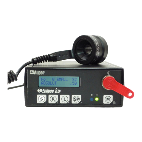
Auper TM6400 Installation guide

Installation and programming guide
TM6400
64 CHANNELS FLOW MONITORING SYSTEM
AND TRANSMITTER

GENERAL INFORMATION
FCC INFORMATION
This device complies with Part 15 of FCC rules. Operation is subject
to the following two conditions:
(1) This device may not cause harmful interference and, (2) this
device must accept any interference received including interference
that may cause undesired operation.
Note: The user is cautioned that any changes or modifications not
expressly approved by the party responsible for FCC compliance
could void the user’s authority to operate the equipment.
No part of this publication may be reproduced, transmitted,
transcribed, stored in a retrieval system, or translated into any
language in any form by any means without the written permission of
Auper Electronic Controls Inc.
LIMITED 5YEAR WARRANTY
Auper Electronic Controls Inc. warrants that this product is in good
working condition, according to its specifications at the time of the
shipment, for a period of FIVE (5) years from the date of purchase.
Should the product, in Auper Electronic Controls Inc opinion,
malfunction within the warranty period, Auper Electronic Controls Inc.
will repair or replace the product without charge. Any replaced parts
become the property of Auper Electronic Controls Inc. This warranty
does not apply to the software component of a product or a product
which has been damaged due to an accident, misuse, abuse,
improper installation, usage not in accordance with product
specifications and instructions, natural or personal disaster or
unauthorized alterations, repairs or modifications.
THIS WARRANTY IS LIMITED TO REPAIR OR REPLACEMENT (AT
AUPER’S OPTION) ONLY AND DOES NOT INCLUDE ANY LABOR
OR TRANSPORTATION CHARGES OR COMPLIANCE WITH ANY
FEDERAL, STATE OR LOCAL LAWS, CODES OR REGULATION.

TM600 FLOW TOTALIZER AND TRANSMITTER
2|P a g e
Notice of any claimed breach of said Warranty must be promptly given
to the Auper authorized dealer from whom the product was purchased
or leased. Upon request, all systems or parts which are claimed to be
defective must be made available for inspection by and/or return to (at
AUPER’S option) such authorized dealer and/or Auper. No repair or
replacement under said warranty will extend the original warranty
period.
THIS WARRANTY IS EXCLUSIVE AND IS IN LIEU OF ALL OTHER
WARRANTIES, ORAL OR WRITTEN, EXPRESS OR IMPLIED,
INCLUDING THE WARRANTIES OF MERCHANTABILITY AND
FITNESS FOR ANY PARTICULAR PURPOSE.
LIMITATIONS
All warranty for this product, expressed or implied, are limited to five
years from the date of purchase and no warranty, expressed or
implied, will apply after that period. No warranties for this product
expressed or implied will apply to any person who purchases the
product in used condition. The liability of Auper Electronic Controls
Inc. with respect to any defective product will be limited to the repair
or replacement of such product.
In no event shall Auper Electronic Controls Inc be responsible or liable
for any damages arising
(a) from the use of the product;
(b) from the loss of use, revenue or profit of the product; or
(c) as a result of any event, circumstances, action or abuse beyond
the control of Auper Electronic Controls Inc.; whether such damage be
direct, indirect, consequential, special or otherwise and whether such
damages are incurred by the person to whom this warranty extends or
a third party.

DISCLAIMER OF OTHER WARRANTIES AND LIABILITIES
While all reasonable care has been taken in preparation of this
product, it is provided “as is,” without warranty as to performance or
fitness except as expressly stated above. The entire risk as to the
quality of output developed with this product is assumed by the user.
Auper Electronic Controls Inc does not warrant that the software or
system will meet any particular requirements of the user, other than
as expressly stated above, and specifically denies any liability for
incidental or consequential damages resulting from the use of this
software or system.
Auper Electronic Controls Inc also specifically denies all liability for
any technical or editorial omissions in its product documentation, and
for any incidental or consequential damages resulting from the
furnishing, performance or use of its documentation.

TM600 FLOW TOTALIZER AND TRANSMITTER
TM6400 Installation & User guide 4|P a g e
TM6400
Real-time flow monitoring system
Package
TM6400 control unit
12 Volts DC transformer @ 1.5 amp min
Flow meter collector box (1 of 4)
25 ft (7.62 m) flow meter collector cable
10 ft (3 M) serial cable or Cat 5 network cable
OPTIONAL
WiFi adapter
USB to serial adapter
Serial printer
Draft Manager Live software

TM6400 FLOW MONITORING SYSTEM
TM6400 Installation & User guide 5|P a g e
INSTALLATION
POSITIONING YOUR SYSTEM
The TM6400 being a control system, should receive the same
installation considerations as an alarm system. It should be installed
in such a way as to be tamper proof that you choose to install it at the
bar, outside the beer cooler or, in the manager’s office. Cables and
connections should be protected and secured out of reach. The
power source should not be installed where it can easily be
disconnected. Do not connect the TM6400 power source to an
electrical outlet that can be turned off at night.
COMMUNICATION
The TM6400 is equipped with two programmable serial ports and an
Ethernet adapter to connect it to a computer network.
The RS-422 port serial port connector is a RJ11 jack (phone jack).
The RS-232 port connector is a Dsub 9 pin connector (male)
RS-422 SPECIFICATIONS
Standard EIA RS-422 Physical Media Twisted Pair Network
Topology Point-to-point
Maximum Distance RS-422 1000 metres (3000 ft)
Mode of Operation Differential
Maximum Baud Rate RS-422 115.2 Kbytes

TM600 FLOW TOTALIZER AND TRANSMITTER
6|P a g e
Voltage Levels −6V to +6V (maximum differential Voltage)
Mark(1) Negative Voltages
Space(0) Positive voltages
Available Signals Tx+, Tx-, Rx-, Rx+ (Full Duplex)
RS-422 connector type RJ11
Using RS-422 and the Auper AP821 RS-422 eight port hub,
you can link several Auper metering systems to the same RS-
232 serial port or USB port of a computer or printer.
RS-232 SPECIFICATIONS
The RS-232 port can be used with one system connected directly to a
serial port of a computer running with the Draft manager software.
Maximum distance RS-232 15.25 metres (50 ft) with straight
cable or 44 metres (147 ft) using UTP Cat 5 cable
RS-232 connector type DB9 male
Maximum Baud Rate RS-232 115kbit/s
ETHERNET ADAPTER
The TM6400 is available with an optional Ethernet adapter you can
use to connect one, or several TM6400, directly to your computer
network to use the Draft Manager Live software. Once connected to a
network port, the adapter can be found and configured by remote
login by our technicians from any PC on the same network. This is
done at the same time as the software installation.
The system is also equipped with a real-time interface. The TM6400
will send the amount served through the Ethernet or serial port two
seconds after the flow meter has stopped recording following a
special communication protocol. To use this feature, you must use the
Draft Manager Live software.

TM6400 FLOW MONITORING SYSTEM
TM6400 Installation & User guide 7|P a g e
RED LED POWER FAIL INDICATOR
The red LED on the TM6400 will flash to signal that there was a
power failure. To stop the LED from flashing you will need to enter
your administrator code.
CONNECTING THE FLOW METERS
Follow the instruction sheet supplied with the flow meters for complete
step by step instructions on how to install the flow meters. Videos are
also available on the Auper YouTube channel accessible from the
web site. The flow meters will be connected to one or 4 flow meter
collector box. The collector boxes are designed to be mounted in beer
coolers. Since the flow meters are supplied with a 25 ft (7.6 M) cable,
you should try to position each collector box in the beer cooler to
reach as many flow meters as possible. Flow meter cables can be
extended should you need to.
WARNING:
The power to the collector boxes comes from the TM6400 through the
collector cables. Always disconnect the power to the TM6400 when
working on the collector(s) or, when connecting or disconnecting the
collector cables.
Figure 1 TM6400 Collector box

TM600 FLOW TOTALIZER AND TRANSMITTER
8|P a g e
One collector box is able to take
up to 16 flow meters. Up to four
collector boxes can be connected
to one TM6400 for a total of 64
flow meters per system.
You will connect the collector
boxes to the TM6400 using a
regular Cat 5 network cable
terminated with RJ45 connectors.
Cables are available for up to 150
ft (46M). Longer cables can be made on demand and can reach 300 ft
(100 M). This is the same kind of cables used for computer networks.
You can find them in computer stores or have them installed by local
computer network contractors. However, you must not connect the
collector cables to the computer network and each cable should
be tested priot to connecting it to the collector and TM6400
system..

TM6400 FLOW MONITORING SYSTEM
TM6400 Installation & User guide 9|P a g e
There are two channels on the TM6400 each able to take one or 2
collector boxes. Channel 1 on the TM6400 (flow meters No.1 to 32)
will take one or two collector boxes. The second collector boxe (flow
meter 17 to 32) connects to the first collector box using the OUT
connector to the IN connector of the first collector box. The same
goes with channel 2 for flow meters 33 to 64.
The ends of flow meter cables have been stripped at the factory. Twist
the wire and then pull the insulation off the wire. Cut the copper wire
to get ¼ in (6mm) exposed only.
Auper flow meters do not need an external power source. There is no
voltage going to the flow meters so you cannot damage them even if
you touch the wires. There is no positive or ground either. You do not
have to worry about polarities.

TM600 FLOW TOTALIZER AND TRANSMITTER
10 |P a g e
Connect the flow meters to terminals 1 to16 and tighten the screws to
secure the connection. DO NOT OVER TIGHEN AS YOU MAY CUT
THE WIRE.
Inspect your connections before closing the cover to make sure that
no wires are touching each other. If two wires are touching, the flow
meter signal will be shorted and the flow meter will not send any
signal to the TM6400.
Connect the network cable to the collector box. Secure all your cables
using cable ties. Loose wires should be secured using cable ties.

TM6400 FLOW MONITORING SYSTEM
TM6400 Installation & User guide 11 |P a g e
CONNECTING THE TM6400
Warning: Although the collector box cable is the same as computer
network cables, the collector box is not a network device. DO NOT
CONNECT THIS CABLE TO ANY SWITCH, ROUTER OR OTHER
ETHERNET DEVICE.
Run the Cat 5 network cable between the junction box and the
TM6400 system.
Securing the connector
Use small cable ties to secure the
connector in place. Slip the cable tie
between the connector’s body and the
tab. The cable tie will prevent the tab
from being pressed thus preventing
anyone from disconnecting the cable.
Securing the flow meter cables and
collector box cables will prevent people
from tampering with the flow meter system. You should visually
inspect the cables regularly.
POWER SUPPLY
Use a 12 Volts DC transformer at minimum 1.5 A to power the
TM6400.
Connect the transformer to a power outlet. Avoid using inexpensive
power bars as the transformer may fall and disconnect. Make sure
the power source cannot be disconnected by the staff. A UPS (battery
backup) is an added security since it will supply power to a TM6400
for a long time in case of power failures insuring continuous power to
the unit.

TM6400 FLOW MONITORING SYSTEM AND TRANSMITTER
TM6400 Installation & User guide 12 |P a g e
POWER UP AND SET UP
The button serves several functions.
1. The numbers will be used for passwords.
2. Arrow signs pointing left and right will be used to move the
cursor, select the line numbers or ports viewed.
3. The minus and plus sign are used to increase or decrease
values.
4. The E (enter) button will be used to validate a choice.
5. The M button will be used to change mode.
6. The LED will blink in case of power loss.
Passwords:
Two different passwords can be programmed
Administrator
Line cleaning
The default factory passwords are 1 2 3 4 followed by E
(enter).
PRESS AND HOLD M and then Press E to enter the programming
modes.
You will be asked to enter a password after your selection.
1.RESET COUNTERS
Press 1 followed by the password and press E.
The system will clear the 64 counters. The counters should not be
cleared when using the software.

TM6400 Installation & User guide 13 |P a g e
2.CLEANING MODE
Press 2 followed by the password and press E.
This puts the system in line cleaning mode. The counters are disabled
when left in this position.
Press 6 (M) to exit.
3. SET UP
Press 3 followed by the password and press E.
1 IMPULSE MODE
Press 1 to enter this mode.
From left to right, 16 dots representing flow meters 1 to 16.
Press the arrows left or right to move the bank of flow meters showed
on display (1 to 16, 17 to 32, 33 to 48, 49 to 64)
The numbers below the pulses (4, 8, 12. 20, 24 ….) followed by a bar
are indicators to help you determine which flow meter number you are
looking at.
When a flow meter is connected to a line, the corresponding
dot is up.
If no flow meter is connected to a line, the corresponding dot is
down.
When a flow meter detects liquid flowing through it, the
corresponding dot will alternate up and down.
If a flow meter is installed backward, the corresponding dot will
be up but will not alternate when product is flowing.

14 |P a g e
You can verify that your flow meters are connected and registering
by serving a little bit of beer at each faucet.
If you had not yet removed the air pocket from your beer
lines, now is the time to do it.
Press M to exit. [Pulse done?]
Press E to confirm.
2. Calibration (Please read carefully)
The TM6400 can be set to measure ounces, litres, gallons etc... To
calibrate, you will serve a measured amount of liquid into a graduated
cylinder during which time the system will count the number pulses
sent by the flow meter. The initial sampling value on display is 20.0
(for 20 Oz).
If you plan on counting ounces leave it there. 20 ounces measured in
a graduated cyclinder at each beer tap is a sufficient amount to
calibrate the metering system accurately. Less will reduce the
accuracy and more is not necessary.
To count litres, you could use a sampling value of 01.0 liter but a half
litre (00.5) is sufficient to calibrate the metering system accurately.
Less will reduce the accuracy and more is not necessary.
To count one for the amount served in a glass (a pint), use a sample
value of 01.0.
The cursor can be moved left and right using the arrow buttons.
Use the + and - to increase or decrease the value.
When you have selected the sampling value to be measured in a
graduated cylinder, press M to start.
How to sample:
TIP: For draft beer, you can kill the foam by spraying WD40 into the
graduated cylinder before serving. You can stop to let the foam settle
down when you are in calibration mode. WD40 does not work with
Stouts and Cream Ales. DISPOSE OF THE CONTENT OF THE
CYLINDER INTO THE SINK. DO NOT SERVE!!!

TM6400 Installation & User guide 15 |P a g e
Serve and measure as accurately as possible the sampling value
using a graduated cylinder at each beer tap. You should calibrate
when the bar is closed. Serving beer to customers while trying to
calibrate the system may cause errors and inaccurate measurements.
After you have served the amount, you can calibrate the flow meters
all at once or, a few at the time. The number of flow meter pulses
registered by the flow meter after the sample value has been served
will be on display to the right of the flow meter number.
Use the arrow buttons to display the other flow meters.
Press the No.4 button (+) to calibrate the flow meter on display only.
Press the E button to calibrate all the flow meters that have pulses
registered after serving the sampling value.
The value on the right will change to the new calibration value. You
can view the calibration values of each line by pressing the arrow
buttons.
In calibration mode, when beer has not been served at some beer
taps, the registered pulses will remain “0000”. The system will not
recalibrate even if you press E to calibrate ALL. Therefore, you can do
some of them, press E to calibrate and move on to other beer taps as
long as ones already calibrated are not used.
RE-SAMPLING
If you have exceeded the amount to measure at one or more of the
beer tape, note which of the taps and move on to measuring the other
ones. After pressing the E button to calibrate all the flow meters, you
can come back and resample the one(s) you are not satisfied with.
Press M to exit calibration mode
Press E to confirm.

16 |P a g e
3. ACCESS
Press 3 to change the two passwords. We recommend using a
password that is simple and easy to remember.
If you do not want to change the first password (administrator), press
E to skip.
Buttons No. 1 2 3 4 and 6 can be used to enter a password up to 7
digits long.
Press and hold M while pressing E to delete the last number entered
to make corrections.
Press E to validate your entry and exit.
4. COMM
Press 4 to enter COMM mode.
System number 00
The system number is used to communicate with the Draft Manager
Live software. The default number is 0. If you have one TM6400,
leave it at 0 since the default number in the software is also 0. If you
have more than one TM6400, you can change the number of the
other systems to 1, 2 3 etc…. Each TM6400 has to be set with a
different number when on the same network. Two systems with the
same number will cause an error since both will respond to the same
command sent by the software.
Press + or - to increase or decrease the system number.
Press M to go to the next mode
Use the Arrows to select the port used to communicate with the
computer.
Choose RS232 if you connect the TM6400 directly to a PC using a
serial 9 pin to USB cable.
Choose RS422 if you connect the TM6400 to an Auper AP821 HUB to
link several system to the same RS-422 network.

TM6400 Installation & User guide 17 |P a g e
Choose Ethernet link if you connect the TM6400 directly to your
computer network using the Ethernet switch or router.
Choose WIFI link if your TM6400 is equipped with this option.
Press the + or – button to change the baud rate which is the speed of
transmission between the TM6400 and the PC.
9600 is the default Windows baud rate. If you change it in the
TM6400, it has to be changed in the software as well.
The TM6400 is designed to operate at 115.2 K for a much faster
transmission rate.
Press M to go to the next mode.
5. FIRMWARE
This mode serves to identify the firmware version and micro processor
unit installed in your TM6400.
Press M to exit.
The system asks [COMM. DONE?]
Press E to exit COMM mode.
OPERATION
RUN MODE
In Run mode, you see the counters on display.
Press the arrow buttons to view the other counters.
Press M to select one of two options:
Press 1 to print a report to a serial printer.
Press 2 to reset the power fail counter.
Enter the password and press E to validate.

18 |P a g e
ANNEX
SERIAL PRINTER SETTINGS
Baud rate: 9600 to 115.2 K
Parity: none
Stop bit: 1
Handshaking: Xon/Xoff
Print columns: 40
USB TO SERIAL CONVERTER
Most computers are not equipped with 9-pin serial ports. A USB to
serial adapter must be used. Drivers are provided with the converter
and must be installed on the computer. Windows will assign the serial
port automatically. You can find to which port your converter has been
assigned at:
Control panel/system/device manager/ports (Com & LPT)
Default Windows serial port settings:
9600 bps
bits
no parity,
2 stop bits
Flux control to none.
P/N: 70-080
Use with Auper null modem serial cable P/N: 70.010
USB to serial converter

TM6400 Installation & User guide 19 |P a g e
RS-422 SERIAL PORT CONNECTIONS
You will use the RS-422 port for the following reasons:
You do not have an available computer network to use the
network adapter.
You wish to connect your TM6400 to a computer more than
150 ft (50M) away.
You have more than one metering system that you want to
connect to the same computer or printer.
Short distance RS-422 connections (no more than 50 ft/ 15M) can be
made using flat modular cables. The cables will connect directly from
the system(s) into the AP821 hub. (Order the cables separately P/N
70-040-X). Modular cables are not twisted and offer no protection
against ambiant noise.
Long distance RS-422 connections can be made using UTP Cat5e 2
pair cable terminated with RJ11 jack. You can order those from the
factory.The cables must be inverted if you make your own.
P/N: 70-042-X (X = length)
RJ11 jacks
RS422 modular cable
Table of contents
Other Auper Measuring Instrument manuals
Popular Measuring Instrument manuals by other brands
Satec
Satec expertmeter EM720 Operation manual
Bosch
Bosch GTL 3 Professional Original instructions
Endress+Hauser
Endress+Hauser Prosonic M FMU42 operating instructions
Altana
Altana BYK wave-scan 3 operating instructions

VOLTCRAFT
VOLTCRAFT HygroCube 100 operating instructions
Wisi
Wisi OL 55 0000 operating manual
