manuals.online logo
Brands
  1. Home
  2. •
  3. Brands
  4. •
  5. Topcon
  6. •
  7. Measuring Instrument
  8. •
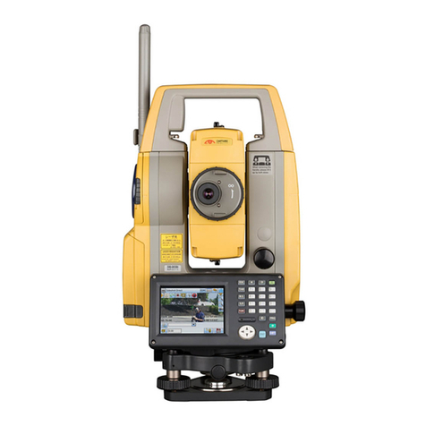
  9. Topcon GM-100 Series Installation guide

Topcon GM-100 Series Installation guide

Battery Charging
The battery (BDC70) was not charged at the factory. Charge the battery
fully before using the instrument.
1. Connect the power cable to the charger and plug the charger into the
wall outlet.
2. Mount the battery in the charger by matching the grooves on the bat-
tery with the guides on the charger. When charging starts, the lamp
starts blinking.
3. The lamp lights when charging is finished.

• Be sure to charge the battery within the charging temperature range.
Charging temperature range: 0 to 40°C
Installing the Battery
1. Slide down the catch on the battery
cover to open.
2. Checking the terminal side on the
battery, insert the battery as shown.

• Do not insert the battery inclined. Doing so may damage the
instrument or battery terminals.
3. Close the battery cover. A click is heard when the cover is secure.
Upon opening, make sure that all the following are included.
Standard Package Components
For the safe use of the product and prevention of injury to operators and other
persons as well as prevention of property damage, items which should be
observed are indicated by an exclamation point within a triangle used with
WARNING and CAUTION statements in this operator’s manual.
The definitions of the indications are listed below. Be sure you understand
them before reading the manual’s main text.
Definition of Indication
General
WARNING Ignoring this indication and making an operation error could
possibly result in death or serious injury to the operator.
CAUTION Ignoring this indication and making an operation error could
possibly result in personal injury or property damage.
This symbol indicates items for which caution (hazard warnings inclusive) is
urged. Specific details are printed in or near the symbol.
This symbol indicates items which are prohibited. Specific details are printed in
or near the symbol.
This symbol indicates items which must always be performed. Specific details
are printed in or near the symbol.
Warning
Do not use the unit in areas exposed to high amounts of dust or ash, in areas
where there is inadequate ventilation, or near combustible materials. An
explosion could occur.
Do not perform disassembly or rebuilding. Fire, electric shock, burns, or
hazardous radiation exposure could result.
Never look at the sun through the telescope. Loss of eyesight could result.
Do not look at reflected sunlight from a prism or other reflecting object through
the telescope. Loss of eyesight could result.
Direct viewing of the sun during sun observation will cause loss of eyesight.
Use solar filter (option) for sun observation.
When securing the instrument in the carrying case make sure to set all the
locks. Failure to do so could result in the instrument falling out while being
carried, causing injury.
Caution
Do not use the carrying case as a footstool. The case is slippery and unstable
so a person could slip and fall off it.
Power Supply
Do not place the instrument in a damaged case or in a case with a damaged
belt. The case or instrument could be dropped and cause injury.
Do not wield or throw the plumb bob. A person could be injured if struck.
Secure handle to main unit. Failure to properly secure the handle could result in
the unit falling off while being carried, causing injury.
Tighten the adjustment tribrach clamp securely. Failure to properly secure the
clamp could result in the tribrach falling off while being carried, causing injury.
Warning
Do not disassemble or rebuild the battery or the battery charger, nor expose to
heavy shocks or vibration. Sparking, fire, electric shock or burns could result.
Do not short circuit. Heat or ignition could result.
Do not place articles such as clothing on the battery charger while charging
batteries. Sparks could be induced, leading to fire.
Do not use voltage other than the specified power supply voltage. Fire or
electrical shock could result.
Do not use batteries other than those designated. An explosion could occur, or
abnormal heat generated, leading to fire.
Do not use damaged power cords, plugs or loose outlets. Fire or electric shock
could result.
Do not use power cords other than those designated. Fire could result.
Use only the specified battery charger to recharge batteries. Other chargers
may be of different voltage rating or polarity, causing sparking which could lead
to fire or burns.
Do not use the battery or charger for any other equipment or purpose. Fire or
burns caused by ignition could result.
Do not heat or throw batteries or chargers into fire. An explosion could occur,
resulting in injury.
To prevent shorting of the battery in storage, apply insulating tape or equivalent
to the terminals. Otherwise shorting could occur resulting in fire or burns.
Do not use the battery or the battery charger if its terminals are wet. Resultant
poor contact or shorting could lead to fire or burns.
Do not connect or disconnect power supply plugs with wet hands. Electric
shock could result.
Caution
Do not touch liquid leaking from batteries. Harmful chemicals could cause
burns or blisters.
Tripod
Bluetooth wireless technology/Wireless LAN
Laser Safety
Refer to "LASER SAFETY INFORMATION" in your manual (PDF).
Caution
When mounting the instrument to the tripod, tighten the centering screw
securely. Failure to tighten the screw properly could result in the instrument
falling off the tripod, causing injury.
Tighten securely the leg fixing screws of the tripod on which the instrument is
mounted. Failure to tighten the screws could result in the tripod collapsing,
causing injury.
Do not carry the tripod with the tripod shoes pointed at other persons. A person
could be injured if struck by the tripod shoes.
Keep hands and feet away from the tripod shoes when fixing the tripod in the
ground. A hand or foot stab wound could result.
Tighten the leg fixing screws securely before carrying the tripod. Failure to
tighten the screws could lead to the tripod legs extending, causing injury.
Warning
Do not use within the vicinity of hospitals. Malfunction of medical equipment
could result.
Use the instrument at a distance of at least 22 cm from anyone with a cardiac
pacemaker. Otherwise, the pacemaker may be adversely affected by the
electromagnetic waves produced and cease to operate as normal.
Do not use onboard aircraft. The aircraft instrumentation may malfunction as a
result.
Do not use within the vicinity of automatic doors, fire alarms and other devices
with automatic controls as the electromagnetic waves produced may adversely
affect operation resulting in an accident.
Precautions for Safe Operation
Using the Battery
Battery
Charger
(110 to 240 V AC)
To outlet
տվ րց
1 Main unit . . . . . . . . . . . . . . . . . . . . . . . . . . . . . 1
2 Battery (BDC70) . . . . . . . . . . . . . . . . . . . . . . . 1
3 Battery charger (CDC68A) . . . . . . . . . . . . . . . 1
4 Power cable (EDC113A/113B/113C etc.) . . . . 1
5 Lens cap . . . . . . . . . . . . . . . . . . . . . . . . . . . . . 1
6 Lens hood . . . . . . . . . . . . . . . . . . . . . . . . . . . . 1
7 Tool pouch . . . . . . . . . . . . . . . . . . . . . . . . . . . 1
8 Precision screwdriver . . . . . . . . . . . . . . . . . . . 1
9 Lens brush . . . . . . . . . . . . . . . . . . . . . . . . . . . 1
10 Hexagonal wrench (1.3 mm/2.5 mm) . . . 1 each
11 Silicon cloth. . . . . . . . . . . . . . . . . . . . . . . . . . . 1
12 Quick Manual (This sheet) . . . . . . . . . . . . . . . 1
13 CD-ROM (Operator's manual) . . . . . . . . . . . . 1
14 Laser caution sign-board . . . . . . . . . . . . . . . . 1
15 Carrying case . . . . . . . . . . . . . . . . . . . . . . . . . 1
16 Carrying strap . . . . . . . . . . . . . . . . . . . . . . . . . 1
17 Export restrictions card (Be sure to read) . . . . 1
• A dedicated power cable for the country or the area where the instrument is purchased is attached.
• Instruments with a laser plummet also include a 1.5 mm hexagonal wrench.
• Instruments with a plate level also include an adjusting pin.
• The Operator's manual is an electronic manual provided in a CD-ROM in PDF format. It is recommended that the manual
files are backed up by transferring to your PC etc. Adobe Acrobat Reader DC is necessary in order to view these documents.
The latest version of Acrobat Reader DC can be downloaded from the Adobe homepage.
• Some types of USB flash drives may not be recognized on the instrument. Even if the procedure of SD formatting enables
any USB flash drives to be recognized, TOPCON CORPORATION cannot guarantee safe operation of them.
Battery
Battery
Cover
Charging lamp
Charging: Flashing.
Charging completion: Lighting up.
Charging time: About 5.5 hours
Press the power key to power ON.
Press and hold (about 1 sec) power key to power OFF.
• If you are experiencing problems with the software, depress the reset
button to reboot the program forcibly. Use a provided hexagonal
wrench (1.3 mm/1.5 mm) or a tapered rod like a pin to depress down
the reset button.

• Avoid using any sharp implement like a needle. Malfunction of the
instrument could result.
• Pressing down the Reset button may result in file and folder data being
lost.
Reset button
Power ON/OFF
GM-100 series
Quick Manual
1019165-01-A
Power key
GM-100_Quick_E.fm 1 ページ 2017年5月22日 月曜日 午後2時52分
For more information contact Synergy Positioning Systems or
visit the Synergy Positioning Systems website at www.synergypositioning.co.nz
All branches: Phone 0800 867 266 Email: [email protected]
1. Press [ANG].
2. Collimate the first target "A".
3. Set the horizontal angle of target "A" to
0°00'00".
Press the [0SET] and press the [YES].
4. Collimate the second target "B".
The horizontal angle and vertical angle of target "B",
which you want to know, are displayed.
V : 80°30'15"
HR: 120°30'40"
0SET HOLD HSET P1
↓
H ANGLE 0 SET
> OK?
--- --- [YES][NO]
V : 80°30'15"
HR: 0°00'00"
0SET HOLD HSET P1
↓
V : 80°30'15"
HR: 132°40'20"
0SET HOLD HSET P1
↓
1. Collimate the target center.
Make sure that setting is applicable to the measure-
ment conditions.
2. Press [ ].
Distance measurement (Continuous measuring)
starts.
• Distance measurement mode can be switched
between continuous measurement/N-time mea-
surement by pressing [MEAS] during a distance
measurement. Current mode is displayed in [ ].
The results of the measurement are displayed.
Hereafter, the results are updated whenever measure-
ment is performed.
Pressing the []key again, the display changes to
horizontal (HR) and vertical (V) angle and slope distance
(SD).

• Pressing trigger key located on the side of the instru-
ment will perform exactly the same operation with
[MEAS].
V : 90°10'20"
HR: 120°30'40"
0SET HOLD HSET P1
↓
HR: 120°30'40"
HD*[r] << m
VD: m
MEAS MODE NP/P P1
↓
HR: 120°30'40"
HD* 131.677 m
VD: -0.396 m
MEAS MODE NP/P P1
↓
V : 90°10'20"
HR: 120°30'40"
SD* 131.678 m
MEAS MODE NP/P P1
↓
Trigger key
Angular Measurement
Target “A”
0°00'00"
Display Functions
Target “A” Target “B”
0°00'00" 132°40'20"
Horizontal angle
Distance Measurement
࣭Press the Starkey [ ], and the Starkey mode is accessed.
In the Starkey mode, it is possible to change the setting
item that is frequently used during measurement.
Measuring screen
Input screen
Menu screen
Tilt screen
Remaining battery power
Targe t
Prism
(No display)
Reflectorless
Reflective sheet
Laser-pointer function
(blinking): Laser-pointer is selected and ON.
Measurement is possible.
The power is poor.
Measurement is impossible.
¨Âìéîëéîç© ¨Âìéîëéîç©
Other displays
disappear.
Î
Ð
N
P
Angle measurement mode
Distance measurement mode
: Bluetooth communication status
V : 80 30'15"
HR: 120 30'40"
0SET HOLD HSET P1
HR: 120 30'40"
HD* 131.677 m
VD: -0.396 m
MEAS MODE NP/P P1
Page number (Next page exists.)
Horizontal distance
Horizontal angle
Relative elevation
Vertical angle
Horizontal angle
Softkey
(This symbol mark of the Bluetooth will be displayed when the total
station is in the sate which can be communicated by Bluetooth.)
X -1'40"
Y 2'20"
EXIT
SELECT A FILE
FN:__________
ALP SPC CLR ENT
Status screen
HR: 120 30'40"
HD*[r] -<<< m
VD: m
MEAS MODE NP/P P1
MENU 1/4
F1:TOP FIELD
F2:DATA COLLECT
F3:LAYOUT P
GM-103
S/N XX123456
VER. X.XXXX_XX
P
Laser is emited
[NUM] / [ALP]
Measurement mode
Electric circular level
Switch between numeric
and alphabetic characters.
(Special mode)
Starkey [ ]
Enter key [ENT]
[ ]
[B.S.]
[ ]
[0] [ ] [ ]
[1] - [9]
Power key [ON]
Illumination key [ ]
[ ][ ][ ]
[ESC]
[FUNC]
Selector key for softkeys
Display unit
V : 80 30'15"
HR: 120 30'40"
0SET HOLD HSET P1
N
P
Nomenclature
2
1
6
4
3
5
7
8
9
11
10
12
13
14
15
2
16
19
17
18
21
20
22
24
23
25
26
27
1 Handle
2 Instrument height mark
3 Battery cover
4 Operation panel
5 Serial connector /
Combined communications
and power source connector
(Low Temperature Model)
6 Circular level
7 Circular level adjusting screws
8 Base plate
9 Levelling foot screw
10 Optical plummet focussing ring
11 Optical plummet eyepiece
(10,11: Not included on instruments
with laser plummet)
12 Display unit
13 Guide light
14 Objective lens (Includes Laser-
pointer function)
15 Handle locking screw
16 Tubular compass slot
17 Vertical clamp
18 Vertical fine motion screw
19 Trigger key
20 External interface hatch (USB port/
Reset button)
21 Horizontal fine motion screw
22 Horizontal clamp
23 Tribrach clamp
24 Telescope eyepiece screw
25 Telescope focussing ring
26 Sighting collimator
27 Instrument center mark
28 Plate level
29 Plate level adjusting screw
28
29
Keys Name of Key Function
{}Starkey
Switches to Starkey mode
This mode is used for each presetting or displaying as follows.
1 Contrast of the display, 2 Reticle illumination, 3 Laser pointer, 4 Tilt
correction, 5 Guide light, 6 Set audio mode, 7 Laser Plummet
{}Coordinate meas.key Switches to coordinate measurement mode
{} Distance meas.key Switches to distance measurement mode
{ANG} Angle meas.key Switches to angle measurement mode
{MENU} Menu key Switches to menu mode
Starts measurement applications and performs various settings
{} Illumination key Lights up the display unit and key
Switches the screen/key backlight and Reticle illumination ON/OFF
{} Ta r g e t k e y Switches between target types (prism mode/Sheet mode/Non-prism mode
(Reflectorless mode))
{FUNC}Function key Switches Starkey mode pages (Laser plummet mounted model only)
Keys Name of Key Function
{0} – {9} /
{.} / {±}
Alphanumeric
characters key
Input letters/figures
For entering alphanumeric characters, see Section 2.4 “How to Enter
Alphanumeric Characters”. in instruction manual.
{ESC} Escape key
• Returns to the measurement mode or previous layer mode from the mode
set
• Switches to data collection mode or layout mode directly from the normal
measurement mode
• It is also possible to use as Record key in normal measurement mode.
For selecting function of Escape key, see Chapter 17 “SELECTING
MODE” . in Instruction manual.
{B.S.} Backspace key Delete a character on the left
{ENT} Enter key Selects/accepts input word/value
{} Power source key Turns ON/OFF of power source (Press and hold: About 1 second)
{F1} –{F4} Soft key
(Function key) Respond to the message displayed
Basic Key Operation
5
Low Temperature Models only
GM-100_Quick_E.fm 2 ページ 2017年5月22日 月曜日 午後2時52分

Other manuals for GM-100 Series

1

Other Topcon Measuring Instrument manuals

Topcon RM-8800 User manual

Topcon

Topcon RM-8800 User manual

Topcon CT-800 User manual

Topcon

Topcon CT-800 User manual

Topcon RD-80SA User manual

Topcon

Topcon RD-80SA User manual

Topcon KR-1W User manual

Topcon

Topcon KR-1W User manual

Topcon RL-VH3A User manual

Topcon

Topcon RL-VH3A User manual

Topcon DIGI-STAR TMR3610 User manual

Topcon

Topcon DIGI-STAR TMR3610 User manual

Topcon ES-62 User manual

Topcon

Topcon ES-62 User manual

Topcon RL-H3C User manual

Topcon

Topcon RL-H3C User manual

Topcon RL-H3C User manual

Topcon

Topcon RL-H3C User manual

Topcon Sokkia FX Series User manual

Topcon

Topcon Sokkia FX Series User manual

Topcon BM-100 Series User manual

Topcon

Topcon BM-100 Series User manual

Topcon IS01 User manual

Topcon

Topcon IS01 User manual

Topcon Motorgrader User manual

Topcon

Topcon Motorgrader User manual

Topcon OS Series User manual

Topcon

Topcon OS Series User manual

Topcon GTS-821A, GTS-822A, GTS-823A, GTS-825A User manual

Topcon

Topcon GTS-821A, GTS-822A, GTS-823A, GTS-825A User manual

Topcon GT560 AUTOLOG User manual

Topcon

Topcon GT560 AUTOLOG User manual

Topcon CL-200 User manual

Topcon

Topcon CL-200 User manual

Topcon UA-10 Series User manual

Topcon

Topcon UA-10 Series User manual

Topcon GREEN LABEL GTS-250 Series User manual

Topcon

Topcon GREEN LABEL GTS-250 Series User manual

Topcon GTS-600 Series User manual

Topcon

Topcon GTS-600 Series User manual

Topcon RL-H5A User manual

Topcon

Topcon RL-H5A User manual

Topcon IM-600 User manual

Topcon

Topcon IM-600 User manual

Topcon HiPer Plus User manual

Topcon

Topcon HiPer Plus User manual

Topcon GTS-230N User manual

Topcon

Topcon GTS-230N User manual

Popular Measuring Instrument manuals by other brands

AutoMeter BCT-460 Controls and functions

AutoMeter

AutoMeter BCT-460 Controls and functions

ABQINDUSTRIAL HT-4000 user guide

ABQINDUSTRIAL

ABQINDUSTRIAL HT-4000 user guide

Co2meter Aranet4 PRO USER MANUAL & DATASHEET

Co2meter

Co2meter Aranet4 PRO USER MANUAL & DATASHEET

B+K precision 8550 Series user manual

B+K precision

B+K precision 8550 Series user manual

Promax 6 manual

Promax

Promax 6 manual

B+K precision 4045B user manual

B+K precision

B+K precision 4045B user manual

Dilog DL6505 operating manual

Dilog

Dilog DL6505 operating manual

Great Plains Industries, Inc. FM-530 Series owner's manual

Great Plains Industries, Inc.

Great Plains Industries, Inc. FM-530 Series owner's manual

In-situ Water Level Tape 100 instruction sheet

In-situ

In-situ Water Level Tape 100 instruction sheet

Master cool R1234yf operating instructions

Master cool

Master cool R1234yf operating instructions

LineEye LE Series quick start guide

LineEye

LineEye LE Series quick start guide

FLOW metrix SAFMAG BETA METER user guide

FLOW metrix

FLOW metrix SAFMAG BETA METER user guide

I-Tech IT9120 Series Programming guide

I-Tech

I-Tech IT9120 Series Programming guide

Evo-lite Infinium 12000 RGB FB4 user manual

Evo-lite

Evo-lite Infinium 12000 RGB FB4 user manual

red lion APOLLO IMR Series instruction manual

red lion

red lion APOLLO IMR Series instruction manual

Delta R4E installation manual

Delta

Delta R4E installation manual

Hilti PS 1000 X-Scan operating instructions

Hilti

Hilti PS 1000 X-Scan operating instructions

Trans-Tek LS502-E instruction manual

Trans-Tek

Trans-Tek LS502-E instruction manual

manuals.online logo
manuals.online logoBrands
  • About & Mission
  • Contact us
  • Privacy Policy
  • Terms and Conditions

Copyright 2025 Manuals.Online. All Rights Reserved.