Osmosis, Osmotic Pressure,
Reverse Osmosis (RO) Process
12
3
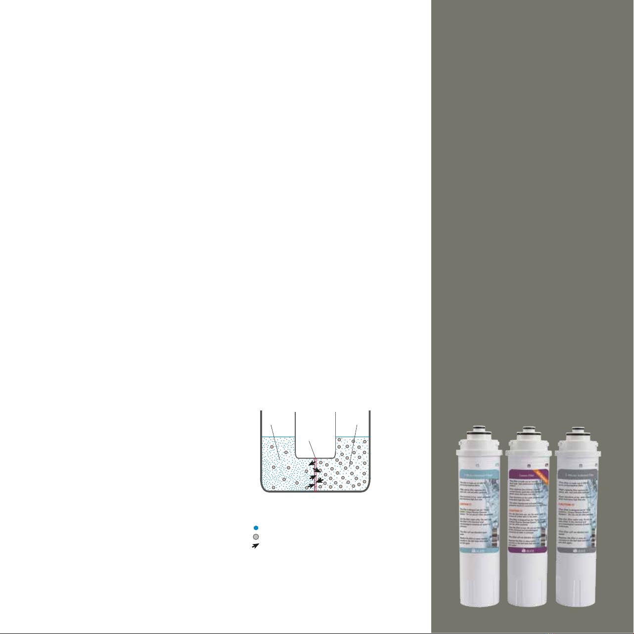
Before the osmosis
4
Osmosis is based on a semi-permeable
membrane and a solution; the semi-permeable
membrane consisting of a thin membrane or a
thin film allows some molecules or ions to pass
and does not allow some molecules or ions to
pass. Examples of a membrane include dell
membranes and egg membrane.
The solution is a homogeneous blend of more
than one substance. I.e. it is the distribution of a
substance in anot her substance
homogeneously with small particles invisible
to the eye. This distribution is called dissolution
and the mixture obtained is called solution.
Generally the substance with less amount in
the mixture is called the solute and the
substance with more amount is called the
solvent. The best solvent among the many
found in nature is water. Water dissolves many
solid, liquid and gaseous substances. Salt water
(sea water) and sugar water (tea) are
well-known solutions.
Many solids exists as dissolved in waters found
in nature. In other words, the water we use is a
solution. The water molecules in this solution
continuously on the move. As the amount of
soluble solids increases, the solid ions occupy
the place of the water molecules. In a water
with high concentration i.e. with more solid
ratio, the number of water molecules is less
than the water with same volume but lower
concentration, as a result, since the number of
moving molecules is less, the thermal internal
energy will be less as well. I.e., the energy of the
solution with low concentration is higher.
When a semi-permeable membrane is placed
between waters with same volume but
different concentrations, while the water
molecules pass through the pores, the solid
particles with a large size cannot pass. Since
there are more water molecules in the water
with low concentration and as a result more
internal energy, more water molecules pass
across the other side. The pass rate depends on
the concentration ratio, temperature and
pressure. The pass continues until the
concentration ratios in both sides are stabilized.
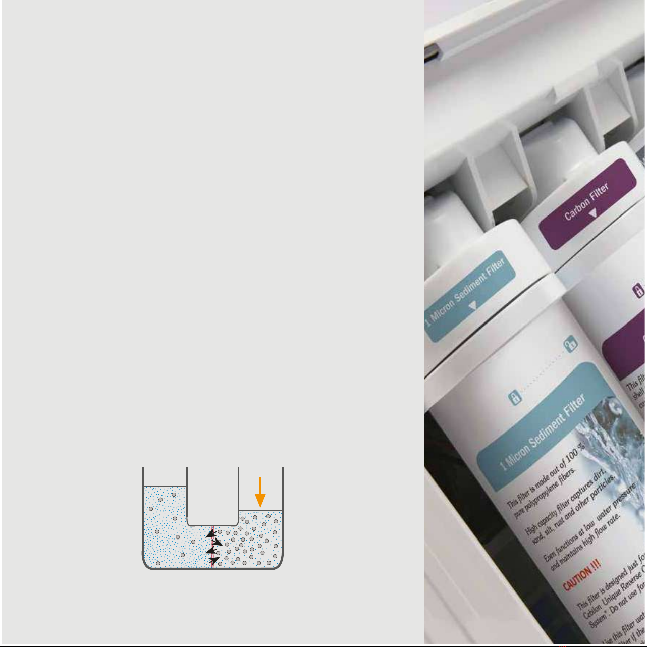
The water level in the high concentration side
increases. This pressure arising from the
potential energy of this rising water column
is stabilized by the Osmotic Pressure. So, the
excess of internal energy in the low
concentration side is stabilized by the potential
energy in the excess of water column in the
high concentration side.
If a pressure equal to the pressure that will be
built up with the excess in the water column is
initially applied to the high concentration side,
Osmosis does not occur. Even, if a pressure
more than this amount is applied, Osmosis is
reversed. Despite its small amount, the water
molecules in the high concentration side
begins passing towards the low concentration
side. This incident created by force of pressure
is called Reverse Osmosis. This incident is
utilized in Reverse Osmosis Systems to separate
the solid substances dissolved in water. The
purpose of water treatment is to have the
water molecules in the high concentration
water (dirty water) pass to the low
concentration side of the water. Osmosis
occurs in the reverse way. In Reverse Osmosis,
osmotic pressure is overcome by applying
pressure and thus the aim is achieved.
Membrane (semi-permeable)
1-
2-
3-
Low concentration
(high osmotic pressure and high internal energy)
High concentration
(low osmotic pressure and low internal energy)
Solvent (water)
Passage of water molecules through the membrane
Solute (solid particles)